

Product Guide
Page 8
... serial ports (one via a board header) • PS/2† keyboard and mouse ports BIOS • Intel/AMI BIOS • Intel® Rapid BIOS Boot • Intel® Express BIOS Update • SMBIOS support Power Management • Support for Advanced Configuration and Power Interface (ACPI) • Support for Suspend to RAM (Instantly Available PC) ✏ NOTE For information about Intel desktop boards, including the Technical Product Specification (TPS), BIOS updates, and device drivers, go to four USB 2.0 ports - Intel Desktop Boards D845GLLY and D845GLAD Product Guide Table...
... serial ports (one via a board header) • PS/2† keyboard and mouse ports BIOS • Intel/AMI BIOS • Intel® Rapid BIOS Boot • Intel® Express BIOS Update • SMBIOS support Power Management • Support for Advanced Configuration and Power Interface (ACPI) • Support for Suspend to RAM (Instantly Available PC) ✏ NOTE For information about Intel desktop boards, including the Technical Product Specification (TPS), BIOS updates, and device drivers, go to four USB 2.0 ports - Intel Desktop Boards D845GLLY and D845GLAD Product Guide Table...

Product Guide
Page 13
...; NOTE The line out connector, located on the back panel, is designed to power either headphones or amplified speakers only. Audio drivers and utilities are connected to the D845GLLY or D845GLAD link on Intel's World Wide Web site at: http://support.intel.com/support/motherboards/desktop 13 Desktop Board Features Integrated Graphics The integrated graphics on Desktop Boards D845GLLY and D845GLAD feature: • Intel 845GL chipset • Intel Extreme Graphics Audio Subsystem The audio subsystem features the following functions...
...; NOTE The line out connector, located on the back panel, is designed to power either headphones or amplified speakers only. Audio drivers and utilities are connected to the D845GLLY or D845GLAD link on Intel's World Wide Web site at: http://support.intel.com/support/motherboards/desktop 13 Desktop Board Features Integrated Graphics The integrated graphics on Desktop Boards D845GLLY and D845GLAD feature: • Intel 845GL chipset • Intel Extreme Graphics Audio Subsystem The audio subsystem features the following functions...

Product Guide
Page 15
... card. You do not need to boot the computer. 15 To use ATA-66/100 features, the following the instructions in the BIOS Setup program. You can boot the computer. If only the supervisor password is set , you must enter either password to run the BIOS Setup program after you install an IDE device (such as a hard drive) in your computer, the IDE auto-configuration utility in the BIOS automatically detects and configures the device...
... card. You do not need to boot the computer. 15 To use ATA-66/100 features, the following the instructions in the BIOS Setup program. You can boot the computer. If only the supervisor password is set , you must enter either password to run the BIOS Setup program after you install an IDE device (such as a hard drive) in your computer, the IDE auto-configuration utility in the BIOS automatically detects and configures the device...
Product Guide
Page 26
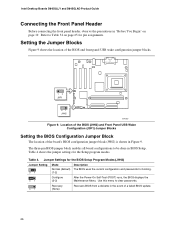
... Figure 9. Intel Desktop Boards D845GLLY and D845GLAD Product Guide Connecting the Front Panel Header Before connecting the front panel header, observe the precautions in "Before You Begin" on page 65 for pin assignments. Jumper Settings for the BIOS Setup Program Modes (J9H2) Jumper Setting 31 Mode Normal (default) (1-2) Description The BIOS uses the current configuration and passwords for the Setup program modes. Table 4 shows the jumper settings for booting. 31 Configure (2-3) After the Power-On Self-Test (POST) runs, the BIOS displays the Maintenance Menu. Refer...
... Figure 9. Intel Desktop Boards D845GLLY and D845GLAD Product Guide Connecting the Front Panel Header Before connecting the front panel header, observe the precautions in "Before You Begin" on page 65 for pin assignments. Jumper Settings for the BIOS Setup Program Modes (J9H2) Jumper Setting 31 Mode Normal (default) (1-2) Description The BIOS uses the current configuration and passwords for the Setup program modes. Table 4 shows the jumper settings for booting. 31 Configure (2-3) After the Power-On Self-Test (POST) runs, the BIOS displays the Maintenance Menu. Refer...

Product Guide
Page 27
... front panel audio cable. 6. Replace the cover. Turn off all peripheral devices connected to Table 31 on page 61. 4. Locate the front panel audio header (J8A1), see Figure 13 on page 65 for the Front Panel USB Wake Configuration Jumper Block (J9F1) Jumper Setting 1-2 13 Configuration Allows wake from ACPI state S1. 2-3 13 Allows wake from the header (this disables the back panel audio connectors). 5. Table 5. Install a jumper on pins 9-10 (rear L channel). 6. Turn off the computer and disconnect the AC power cord...
... front panel audio cable. 6. Replace the cover. Turn off all peripheral devices connected to Table 31 on page 61. 4. Locate the front panel audio header (J8A1), see Figure 13 on page 65 for the Front Panel USB Wake Configuration Jumper Block (J9F1) Jumper Setting 1-2 13 Configuration Allows wake from ACPI state S1. 2-3 13 Allows wake from the header (this disables the back panel audio connectors). 5. Table 5. Install a jumper on pins 9-10 (rear L channel). 6. Turn off the computer and disconnect the AC power cord...

Product Guide
Page 28
.... Intel Desktop Boards D845GLLY and D845GLAD Product Guide Clearing Passwords This procedure assumes that you confirm clearing the password. Disconnect the computer's power cord from the AC power source. 11. Find the configuration jumper block (see Figure 9). 5. Disconnect the computer's power cord from the AC power source (wall outlet or power adapter). 3. Setup displays the maintenance menu. 8. Turn off the computer. Replace the cover, plug in the computer and the configuration jumper block is installed...
.... Intel Desktop Boards D845GLLY and D845GLAD Product Guide Clearing Passwords This procedure assumes that you confirm clearing the password. Disconnect the computer's power cord from the AC power source. 11. Find the configuration jumper block (see Figure 9). 5. Disconnect the computer's power cord from the AC power source (wall outlet or power adapter). 3. Setup displays the maintenance menu. 8. Turn off the computer. Replace the cover, plug in the computer and the configuration jumper block is installed...

Product Guide
Page 37
... The BIOS Setup menus described in this section apply to the Intel Desktop Board D845GLLY/D845GLAD Technical Product Specification or the Intel World Wide Web site: http://support.intel.com/support/motherboards/desktop ✏ NOTE For reference purposes, you make changes to the settings, update this record. ✏ NOTE The Setup menus described in some of the Setup menu screens. BIOS Setup Program Menu Bar Maintenance Clears passwords and Boot Integrity Service (BIS)* credentials, and configures extended configuration memory settings Main Allocates...
... The BIOS Setup menus described in this section apply to the Intel Desktop Board D845GLLY/D845GLAD Technical Product Specification or the Intel World Wide Web site: http://support.intel.com/support/motherboards/desktop ✏ NOTE For reference purposes, you make changes to the settings, update this record. ✏ NOTE The Setup menus described in some of the Setup menu screens. BIOS Setup Program Menu Bar Maintenance Clears passwords and Boot Integrity Service (BIS)* credentials, and configures extended configuration memory settings Main Allocates...

Product Guide
Page 38
...Boot Integrity Service (BIS) credentials. Table 7. Clears the Wired for information about the BIS, refer to clear the Setup passwords. Displays processor's Microcode Update Revision. * For information about setting configure mode. Intel Desktop Boards D845GLLY and D845GLAD Product Guide Table 7 shows the function keys available for the current menu Save the current values and exits the BIOS Setup program Exits the menu Maintenance Menu Maintenance Main Advanced Security Power Boot Exit The menu shown in configure mode. Table 8. BIOS Setup Program Function Keys BIOS...
...Boot Integrity Service (BIS) credentials. Table 7. Clears the Wired for information about the BIS, refer to clear the Setup passwords. Displays processor's Microcode Update Revision. * For information about setting configure mode. Intel Desktop Boards D845GLLY and D845GLAD Product Guide Table 7 shows the function keys available for the current menu Save the current values and exits the BIOS Setup program Exits the menu Maintenance Menu Maintenance Main Advanced Security Power Boot Exit The menu shown in configure mode. Table 8. BIOS Setup Program Function Keys BIOS...
Product Guide
Page 45
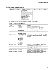
... connected IDE device. Using the Setup Program IDE Configuration Submenu Maintenance Main Advanced Security Power Boot Exit PCI Configuration Boot Configuration Peripheral Configuration IDE Configuration Diskette Configuration Event Log Configuration Video Configuration USB Configuration Chipset Configuration This submenu shown in the system. IDE Configuration Submenu Feature Options IDE Controller • Disabled • Primary • Secondary • Both (default) PCI IDE Bus Master Hard Disk Pre-Delay Primary IDE Master • Disabled • Enabled (default...
... connected IDE device. Using the Setup Program IDE Configuration Submenu Maintenance Main Advanced Security Power Boot Exit PCI Configuration Boot Configuration Peripheral Configuration IDE Configuration Diskette Configuration Event Log Configuration Video Configuration USB Configuration Chipset Configuration This submenu shown in the system. IDE Configuration Submenu Feature Options IDE Controller • Disabled • Primary • Secondary • Both (default) PCI IDE Bus Master Hard Disk Pre-Delay Primary IDE Master • Disabled • Enabled (default...

Product Guide
Page 46
...; Auto (default) • 0 • 1 • 2 • 3 • 4 • Disabled (default) • Mode 0 • Mode 1 • Mode 2 • Mode 3 • Mode 4 • Mode 5 None Specifies number of sectors per block for IDE devices. Displays the type of drive installed. Intel Desktop Boards D845GLLY and D845GLAD Product Guide Primary/Secondary IDE Master/Slave Submenus Maintenance Main Advanced Security PCI Configuration Boot Configuration Peripheral Configuration IDE Configuration Diskette Configuration Event Log Configuration Video Configuration USB Configuration Chipset...
...; Auto (default) • 0 • 1 • 2 • 3 • 4 • Disabled (default) • Mode 0 • Mode 1 • Mode 2 • Mode 3 • Mode 4 • Mode 5 None Specifies number of sectors per block for IDE devices. Displays the type of drive installed. Intel Desktop Boards D845GLLY and D845GLAD Product Guide Primary/Secondary IDE Master/Slave Submenus Maintenance Main Advanced Security PCI Configuration Boot Configuration Peripheral Configuration IDE Configuration Diskette Configuration Event Log Configuration Video Configuration USB Configuration Chipset...
Product Guide
Page 47
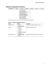
... • 2.88 MB 3½" • Disabled (default) • Enabled Configures the integrated diskette controller. Disables or enables diskette drive write protection. 47 Using the Setup Program Diskette Configuration Submenu Maintenance Main Advanced Security Power Boot Exit PCI Configuration Boot Configuration Peripheral Configuration IDE Configuration Diskette Configuration Event Log Configuration Video Configuration USB Configuration Chipset Configuration This submenu shown in Table 16 is used to configure the diskette drive. Selects the diskette drive type. Table 16.
... • 2.88 MB 3½" • Disabled (default) • Enabled Configures the integrated diskette controller. Disables or enables diskette drive write protection. 47 Using the Setup Program Diskette Configuration Submenu Maintenance Main Advanced Security Power Boot Exit PCI Configuration Boot Configuration Peripheral Configuration IDE Configuration Diskette Configuration Event Log Configuration Video Configuration USB Configuration Chipset Configuration This submenu shown in Table 16 is used to configure the diskette drive. Selects the diskette drive type. Table 16.

Product Guide
Page 50
... support for legacy USB. 50 USB Configuration Submenu Feature Options High Speed USB Legacy USB Support • Disabled • Enabled (default) • Disabled • Enabled (default) Description Disable this option when a USB 2.0 driver is used to configure USB features. Intel Desktop Boards D845GLLY and D845GLAD Product Guide USB Configuration Submenu Maintenance Main Advanced Security Power Boot Exit PCI Configuration Boot Configuration Peripheral Configuration IDE Configuration Diskette Configuration Event Log Configuration Video Configuration USB Configuration...
... support for legacy USB. 50 USB Configuration Submenu Feature Options High Speed USB Legacy USB Support • Disabled • Enabled (default) • Disabled • Enabled (default) Description Disable this option when a USB 2.0 driver is used to configure USB features. Intel Desktop Boards D845GLLY and D845GLAD Product Guide USB Configuration Submenu Maintenance Main Advanced Security Power Boot Exit PCI Configuration Boot Configuration Peripheral Configuration IDE Configuration Diskette Configuration Event Log Configuration Video Configuration USB Configuration...
Product Guide
Page 54
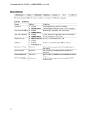
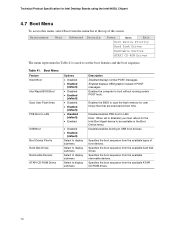
...Rapid BIOS Boot Scan User Flash Area PXE Boot to set the boot features and the boot sequence. Enabled displays OEM logo instead of boot devices. Specifies the boot sequence from the available ATAPI CD-ROM drives. 54 Specifies the boot sequence from the available types of POST messages. Intel Desktop Boards D845GLLY and D845GLAD Product Guide Boot Menu Maintenance Main Advanced Security Power Boot Exit The menu shown in Table 24 is used to LAN USB Boot Boot Device Priority Hard Disk Drives Removable Devices ATAPI CD-ROM Drives Options • Disabled • Enabled (default...
...Rapid BIOS Boot Scan User Flash Area PXE Boot to set the boot features and the boot sequence. Enabled displays OEM logo instead of boot devices. Specifies the boot sequence from the available ATAPI CD-ROM drives. 54 Specifies the boot sequence from the available types of POST messages. Intel Desktop Boards D845GLLY and D845GLAD Product Guide Boot Menu Maintenance Main Advanced Security Power Boot Exit The menu shown in Table 24 is used to LAN USB Boot Boot Device Priority Hard Disk Drives Removable Devices ATAPI CD-ROM Drives Options • Disabled • Enabled (default...
D845GL_Boards_TechProdSpec
Page 46
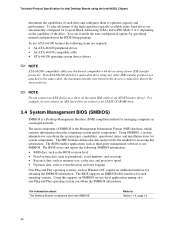
..., require an additional interface for accessing this support, an SMBIOS service-level application running on a non-Plug and Play operating system can override the auto-configuration options by specifying manual configuration in a managed network. The BIOS enables applications such as an ATAPI master device. Technical Product Specification for Intel Desktop Boards using the Intel 845GL Chipset determines the capabilities of each drive and configures them to PIO Mode 3 or 4, depending on the capability...
..., require an additional interface for accessing this support, an SMBIOS service-level application running on a non-Plug and Play operating system can override the auto-configuration options by specifying manual configuration in a managed network. The BIOS enables applications such as an ATAPI master device. Technical Product Specification for Intel Desktop Boards using the Intel 845GL Chipset determines the capabilities of each drive and configures them to PIO Mode 3 or 4, depending on the capability...
D845GL_Boards_TechProdSpec
Page 51
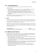
... be used. In the Boot Menu: • Set the hard disk drive as the first boot device. In the Peripheral Configuration submenu, disable the LAN device if it is possible to optimize the boot process to four seconds of painting complex graphic images and changing video modes. • Enabled Intel Rapid BIOS Boot. This is the user mode. • If only the supervisor password is set, pressing the key at all the Setup options in the BIOS Setup Program's Security Menu. If...
... be used. In the Boot Menu: • Set the hard disk drive as the first boot device. In the Peripheral Configuration submenu, disable the LAN device if it is possible to optimize the boot process to four seconds of painting complex graphic images and changing video modes. • Enabled Intel Rapid BIOS Boot. This is the user mode. • If only the supervisor password is set, pressing the key at all the Setup options in the BIOS Setup Program's Security Menu. If...
D845GL_Boards_TechProdSpec
Page 53
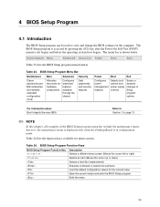
... Load the default configuration values for menu screens. BIOS Setup Program Menu Bar Maintenance Main Advanced Security Clears passwords and BIS credentials and enables extended configuration mode Allocates resources for hardware components Configures advanced features available through the chipset Sets passwords and security features Power Boot Exit Configures power management features Selects boot options and power supply controls Saves or discards changes to Setup program options For information about Boot Integrity Services (BIS) Refer to view and change the BIOS settings...
... Load the default configuration values for menu screens. BIOS Setup Program Menu Bar Maintenance Main Advanced Security Clears passwords and BIS credentials and enables extended configuration mode Allocates resources for hardware components Configures advanced features available through the chipset Sets passwords and security features Power Boot Exit Configures power management features Selects boot options and power supply controls Saves or discards changes to Setup program options For information about Boot Integrity Services (BIS) Refer to view and change the BIOS settings...
D845GL_Boards_TechProdSpec
Page 60
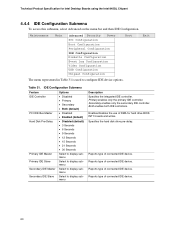
... Video Configuration USB Configuration Chipset Configuration Boot The menu represented in Table 31 is used to display submenu Description Specifies the integrated IDE controller. Both enables both IDE controllers. Enables/disables the use of DMA for Intel Desktop Boards using the Intel 845GL Chipset 4.4.4 IDE Configuration Submenu To access this submenu, select Advanced on the menu bar and then IDE Configuration. Specifies the hard disk drive pre-delay. Reports type of connected IDE device. 60 Primary enables only the primary IDE controller. IDE Configuration Submenu Feature IDE...
... Video Configuration USB Configuration Chipset Configuration Boot The menu represented in Table 31 is used to display submenu Description Specifies the integrated IDE controller. Both enables both IDE controllers. Enables/disables the use of DMA for Intel Desktop Boards using the Intel 845GL Chipset 4.4.4 IDE Configuration Submenu To access this submenu, select Advanced on the menu bar and then IDE Configuration. Specifies the hard disk drive pre-delay. Reports type of connected IDE device. 60 Primary enables only the primary IDE controller. IDE Configuration Submenu Feature IDE...
D845GL_Boards_TechProdSpec
Page 70
...Desktop Boards using the Intel 845GL Chipset 4.7 Boot Menu To access this menu, select Boot from the menu bar at boot time. Maintenance Main Advanced Security Power Boot Exit Boot Device Priority Hard Disk Drives Removable Devices ATAPI CD-ROM Drives The menu represented in the Boot Device menu. Enables the BIOS to set to Enabled, you must reboot for user binary files that are executed at the top of POST messages. Specifies the boot sequence from the available removable devices. Specifies the boot sequence from the available hard disk drives. Enabled displays...
...Desktop Boards using the Intel 845GL Chipset 4.7 Boot Menu To access this menu, select Boot from the menu bar at boot time. Maintenance Main Advanced Security Power Boot Exit Boot Device Priority Hard Disk Drives Removable Devices ATAPI CD-ROM Drives The menu represented in the Boot Device menu. Enables the BIOS to set to Enabled, you must reboot for user binary files that are executed at the top of POST messages. Specifies the boot sequence from the available removable devices. Specifies the boot sequence from the available hard disk drives. Enabled displays...
D845GL_Boards_TechProdSpec
Page 77
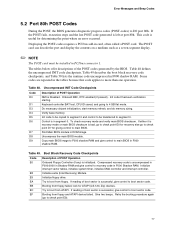
... (Intel Recovery) Module. Try to boot from floppy. Displaying the POST-codes requires a PCI bus add-in ROM image. Table 49. Initialize floppy drive. Try to boot from ATAPI. Retry the booting procedure again (go to check point D7 for determining the point where an error occurred. Keyboard controller BAT test, CPU ID saved, and going to main BIOS in F000 shadow RAM. Find Main BIOS module in card, often called a POST card. If reading of boot...
... (Intel Recovery) Module. Try to boot from floppy. Displaying the POST-codes requires a PCI bus add-in ROM image. Table 49. Initialize floppy drive. Try to boot from ATAPI. Retry the booting procedure again (go to check point D7 for determining the point where an error occurred. Keyboard controller BAT test, CPU ID saved, and going to main BIOS in F000 shadow RAM. Find Main BIOS module in card, often called a POST card. If reading of boot...
D845GL_Boards_SpecUpdate09
Page 16
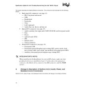
.../2* keyboard and mouse USB Parallel port Serial port VGA LAN (optional) Audio (line out, line in, and mic in) • Internal I/O connectors (see page 14) Audio (auxiliary line input and ATAPI CD-ROM, and front panel audio) Fans Power Add-in boards (PCI) IDE Diskette drive Chassis intrusion • External I/O connectors (see page 19) Front panel USB Front panel (power/sleep/message-waiting LED, power switch, hard drive...
.../2* keyboard and mouse USB Parallel port Serial port VGA LAN (optional) Audio (line out, line in, and mic in) • Internal I/O connectors (see page 14) Audio (auxiliary line input and ATAPI CD-ROM, and front panel audio) Fans Power Add-in boards (PCI) IDE Diskette drive Chassis intrusion • External I/O connectors (see page 19) Front panel USB Front panel (power/sleep/message-waiting LED, power switch, hard drive...


