Product Guide
Page 4
Intel Desktop Boards D845GLLY and D845GLAD Product Guide Installing and Removing Memory 23 Installing DIMMs ...24 Removing DIMMs ...24 Connecting the IDE Cable 25 Connecting the Front Panel Header 26 Setting the Jumper Blocks 26 Setting the BIOS Configuration Jumper Block 26 Setting the Front Panel USB Wake Configuration Jumper Block 27 Installing the Front Panel Audio Solution (Optional 27 Installing a Front Panel USB Solution 27 Clearing Passwords...28 Replacing the Battery ...29 3 Updating the BIOS Updating the BIOS with the Intel® Express BIOS Update Utility 33 Updating the ...
Intel Desktop Boards D845GLLY and D845GLAD Product Guide Installing and Removing Memory 23 Installing DIMMs ...24 Removing DIMMs ...24 Connecting the IDE Cable 25 Connecting the Front Panel Header 26 Setting the Jumper Blocks 26 Setting the BIOS Configuration Jumper Block 26 Setting the Front Panel USB Wake Configuration Jumper Block 27 Installing the Front Panel Audio Solution (Optional 27 Installing a Front Panel USB Solution 27 Clearing Passwords...28 Replacing the Battery ...29 3 Updating the BIOS Updating the BIOS with the Intel® Express BIOS Update Utility 33 Updating the ...

Product Guide
Page 6
... CD-ROM Drives Submenu 56 29. Front Panel USB 2.0 Header (J9F2 65 32. DMA Channels...66 35. Beep Codes ...69 37. BIOS Setup Program Menu Bar 37 7. Boot Configuration Submenu 42 13. Security Menu...52 22. Boot Device Priority Submenu 55 26. Exit Menu...57 30. Intel Desktop Boards D845GLLY and D845GLAD Product Guide Tables 1. ACPI Submenu ...53 24. Removable Devices Submenu 56 28. Front Panel Audio Header Signal Names (J8A1 61 31. Feature Summary ...7 2. Jumper Settings for the BIOS Setup Program Modes...
... CD-ROM Drives Submenu 56 29. Front Panel USB 2.0 Header (J9F2 65 32. DMA Channels...66 35. Beep Codes ...69 37. BIOS Setup Program Menu Bar 37 7. Boot Configuration Submenu 42 13. Security Menu...52 22. Boot Device Priority Submenu 55 26. Exit Menu...57 30. Intel Desktop Boards D845GLLY and D845GLAD Product Guide Tables 1. ACPI Submenu ...53 24. Removable Devices Submenu 56 28. Front Panel Audio Header Signal Names (J8A1 61 31. Feature Summary ...7 2. Jumper Settings for the BIOS Setup Program Modes...

Product Guide
Page 8
... drive interface • One parallel port • Two serial ports (one via a board header) • PS/2† keyboard and mouse ports BIOS • Intel/AMI BIOS • Intel® Rapid BIOS Boot • Intel® Express BIOS Update • SMBIOS support Power Management • Support for Advanced Configuration and Power Interface (ACPI) • Support for Suspend to RAM (Instantly Available PC) ✏ NOTE For information about Intel desktop boards, including the Technical Product Specification (TPS), BIOS updates, and device drivers, go to four USB 2.0 ports - Two ports...
... drive interface • One parallel port • Two serial ports (one via a board header) • PS/2† keyboard and mouse ports BIOS • Intel/AMI BIOS • Intel® Rapid BIOS Boot • Intel® Express BIOS Update • SMBIOS support Power Management • Support for Advanced Configuration and Power Interface (ACPI) • Support for Suspend to RAM (Instantly Available PC) ✏ NOTE For information about Intel desktop boards, including the Technical Product Specification (TPS), BIOS updates, and device drivers, go to four USB 2.0 ports - Two ports...

Product Guide
Page 10
... D845GLAD, refer to the Intel desktop board and/or power supply. Items A and E in damage to the Intel World Wide Web site at: http://support.intel.com/support/motherboards/desktop/ For instructions on installing or upgrading the processor, see Chapter 2 on page 19. Both desktop boards have two 12 V compliant power supply connectors that are not included with the Intel desktop board and must be removed and replaced to the Intel 845GL chipset and Intel Pentium 4 processor. Table 2. Processors Supported by the Desktop Board Type...
... D845GLAD, refer to the Intel desktop board and/or power supply. Items A and E in damage to the Intel World Wide Web site at: http://support.intel.com/support/motherboards/desktop/ For instructions on installing or upgrading the processor, see Chapter 2 on page 19. Both desktop boards have two 12 V compliant power supply connectors that are not included with the Intel desktop board and must be removed and replaced to the Intel 845GL chipset and Intel Pentium 4 processor. Table 2. Processors Supported by the Desktop Board Type...

Product Guide
Page 13
...://support.intel.com/support/motherboards/desktop/ LAN Subsystem (Optional) The optional Intel 82562ET (with status indicator LEDs • Programmable transit threshold • Configurable EEPROM that contains the MAC address LAN Subsystem Software For LAN software and drivers, refer to the D845GLLY or D845GLAD link on the back panel, is designed to this output. Audio drivers and utilities are connected to power either headphones or amplified speakers only. The Intel 82562ET provides the following : • Intel 845GL chipset...
...://support.intel.com/support/motherboards/desktop/ LAN Subsystem (Optional) The optional Intel 82562ET (with status indicator LEDs • Programmable transit threshold • Configurable EEPROM that contains the MAC address LAN Subsystem Software For LAN software and drivers, refer to the D845GLLY or D845GLAD link on the back panel, is designed to this output. Audio drivers and utilities are connected to power either headphones or amplified speakers only. The Intel 82562ET provides the following : • Intel 845GL chipset...

Product Guide
Page 15
... access Setup. Desktop Board Features Expansion Slots Desktop Boards D845GLLY and D845GLAD have four PCI bus add-in card. BIOS The BIOS provides the Power-On Self-Test (POST), the BIOS Setup program, the PCI and IDE auto-configuration utilities, and the video BIOS. You do not need to view and change all Setup options. If only the supervisor password is stored in the BIOS automatically detects and configures the device for that restrict whether the BIOS Setup program can be updated by specifying manual configuration...
... access Setup. Desktop Board Features Expansion Slots Desktop Boards D845GLLY and D845GLAD have four PCI bus add-in card. BIOS The BIOS provides the Power-On Self-Test (POST), the BIOS Setup program, the PCI and IDE auto-configuration utilities, and the video BIOS. You do not need to view and change all Setup options. If only the supervisor password is stored in the BIOS automatically detects and configures the device for that restrict whether the BIOS Setup program can be updated by specifying manual configuration...
Product Guide
Page 26
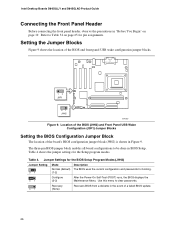
... menu to clear passwords. 31 Recovery (None) Recovers BIOS from a diskette in Figure 9. Jumper Settings for the BIOS Setup Program Modes (J9H2) Jumper Setting 31 Mode Normal (default) (1-2) Description The BIOS uses the current configuration and passwords for the Setup program modes. Setting the Jumper Blocks Figure 9 shows the location of a failed BIOS update. 26 Refer to be done in BIOS Setup. The three-pin BIOS jumper block enables all board configurations to Table 32 on page 19. Intel Desktop Boards D845GLLY and D845GLAD Product Guide Connecting the Front Panel Header...
... menu to clear passwords. 31 Recovery (None) Recovers BIOS from a diskette in Figure 9. Jumper Settings for the BIOS Setup Program Modes (J9H2) Jumper Setting 31 Mode Normal (default) (1-2) Description The BIOS uses the current configuration and passwords for the Setup program modes. Setting the Jumper Blocks Figure 9 shows the location of a failed BIOS update. 26 Refer to be done in BIOS Setup. The three-pin BIOS jumper block enables all board configurations to Table 32 on page 19. Intel Desktop Boards D845GLLY and D845GLAD Product Guide Connecting the Front Panel Header...

Product Guide
Page 27
... Replacing Desktop Board Components Setting the Front Panel USB Wake Configuration Jumper Block The 3-pin front panel USB wake configuration jumper block, labeled J9F1, enables configuration of the two front panel USB ports. Turn off the computer and disconnect the AC power cord. 3. Install a correctly keyed and shielded front panel audio cable. 6. Remove the front panel audio cable. 4. Replace the cover. Installing a Front Panel Audio Solution (Optional) To install the cable that connects the front panel audio solution to S3). Remove the two jumpers from front panel USB ports...
... Replacing Desktop Board Components Setting the Front Panel USB Wake Configuration Jumper Block The 3-pin front panel USB wake configuration jumper block, labeled J9F1, enables configuration of the two front panel USB ports. Turn off the computer and disconnect the AC power cord. 3. Install a correctly keyed and shielded front panel audio cable. 6. Remove the front panel audio cable. 4. Replace the cover. Installing a Front Panel Audio Solution (Optional) To install the cable that connects the front panel audio solution to S3). Remove the two jumpers from front panel USB ports...

Product Guide
Page 28
... it to boot. 7. Intel Desktop Boards D845GLLY and D845GLAD Product Guide Clearing Passwords This procedure assumes that you confirm clearing the password. Remove the computer cover. 4. Replace the cover, plug in the computer and the configuration jumper block is installed in the computer, turn on the computer. 28 Turn off the computer. Find the configuration jumper block (see Figure 9). 5. Use the arrow keys to normal mode. 1. Setup displays the maintenance menu. 8. Disconnect the computer's power cord from...
... it to boot. 7. Intel Desktop Boards D845GLLY and D845GLAD Product Guide Clearing Passwords This procedure assumes that you confirm clearing the password. Remove the computer cover. 4. Replace the cover, plug in the computer and the configuration jumper block is installed in the computer, turn on the computer. 28 Turn off the computer. Find the configuration jumper block (see Figure 9). 5. Use the arrow keys to normal mode. 1. Setup displays the maintenance menu. 8. Disconnect the computer's power cord from...

Product Guide
Page 37
... the Intel Desktop Board D845GLLY/D845GLAD Technical Product Specification or the Intel World Wide Web site: http://support.intel.com/support/motherboards/desktop ✏ NOTE For reference purposes, you make changes to the desktop boards with other BIOS identifiers might have differences in this section may not show the latest settings. Table 6. Desktop boards with BIOS identifier LY84510A.86A. BIOS Setup Program Menu Bar Maintenance Clears passwords and Boot Integrity Service (BIS)* credentials, and configures extended configuration memory settings Main Allocates...
... the Intel Desktop Board D845GLLY/D845GLAD Technical Product Specification or the Intel World Wide Web site: http://support.intel.com/support/motherboards/desktop ✏ NOTE For reference purposes, you make changes to the desktop boards with other BIOS identifiers might have differences in this section may not show the latest settings. Table 6. Desktop boards with BIOS identifier LY84510A.86A. BIOS Setup Program Menu Bar Maintenance Clears passwords and Boot Integrity Service (BIS)* credentials, and configures extended configuration memory settings Main Allocates...

Product Guide
Page 38
... used to the Intel Web site at: http://developer.intel.com/design/security/index1.htm 38 Maintenance Menu Feature Clear All Passwords Clear BIS Credentials CPU Stepping Signature CPU Microcode Update Revision Options • Ok • Cancel • Ok • Cancel No options No options Description Clears both the user and supervisor passwords. Clears the Wired for menu screens. Intel Desktop Boards D845GLLY and D845GLAD Product Guide Table 7 shows the function keys available for Management Boot Integrity Service...
... used to the Intel Web site at: http://developer.intel.com/design/security/index1.htm 38 Maintenance Menu Feature Clear All Passwords Clear BIS Credentials CPU Stepping Signature CPU Microcode Update Revision Options • Ok • Cancel • Ok • Cancel No options No options Description Clears both the user and supervisor passwords. Clears the Wired for menu screens. Intel Desktop Boards D845GLLY and D845GLAD Product Guide Table 7 shows the function keys available for Management Boot Integrity Service...

Product Guide
Page 40
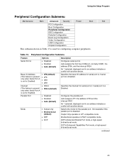
... This menu is used to set advanced features that are available through the chipset. When selected, displays the PCI Configuration submenu. When selected, displays the Boot Configuration submenu. Specifies type of connected IDE device. Configures USB features. Intel Desktop Boards D845GLLY and D845GLAD Product Guide Advanced Menu Maintenance Main Advanced Security Power Boot Exit PCI Configuration Boot Configuration Peripheral Configuration IDE Configuration Diskette Configuration Event Log Configuration Video Configuration USB Configuration Chipset Configuration...
... This menu is used to set advanced features that are available through the chipset. When selected, displays the PCI Configuration submenu. When selected, displays the Boot Configuration submenu. Specifies type of connected IDE device. Configures USB features. Intel Desktop Boards D845GLLY and D845GLAD Product Guide Advanced Menu Maintenance Main Advanced Security Power Boot Exit PCI Configuration Boot Configuration Peripheral Configuration IDE Configuration Diskette Configuration Event Log Configuration Video Configuration USB Configuration Chipset Configuration...
Product Guide
Page 43
...PCI Configuration Boot Configuration Peripheral Configuration IDE Configuration Diskette Configuration Event Log Configuration Video Configuration USB Configuration Chipset Configuration This submenu shown in Table 13 is used for serial port A, if serial port A is Enabled. Table 13. Selects the mode for serial port A, if serial port A is Enabled. Bi-directional operates in AT†-compatible mode. Peripheral Configuration Submenu Feature Serial Port A Options • Disabled • Enabled • Auto (default) Base I /O address for the parallel port. An * (asterisk) displayed...
...PCI Configuration Boot Configuration Peripheral Configuration IDE Configuration Diskette Configuration Event Log Configuration Video Configuration USB Configuration Chipset Configuration This submenu shown in Table 13 is used for serial port A, if serial port A is Enabled. Table 13. Selects the mode for serial port A, if serial port A is Enabled. Bi-directional operates in AT†-compatible mode. Peripheral Configuration Submenu Feature Serial Port A Options • Disabled • Enabled • Auto (default) Base I /O address for the parallel port. An * (asterisk) displayed...
Product Guide
Page 45
...device. Primary enables only the primary IDE controller. Allows for a PCI device to detect IDE drives in Table 14 is used to configure IDE device options. Reports type of connected IDE device. When selected, displays the Primary IDE Master submenu. When selected, displays the Primary IDE Slave submenu. Using the Setup Program IDE Configuration Submenu Maintenance Main Advanced Security Power Boot Exit PCI Configuration Boot Configuration Peripheral Configuration IDE Configuration Diskette Configuration Event Log Configuration Video Configuration USB Configuration Chipset...
...device. Primary enables only the primary IDE controller. Allows for a PCI device to detect IDE drives in Table 14 is used to configure IDE device options. Reports type of connected IDE device. When selected, displays the Primary IDE Master submenu. When selected, displays the Primary IDE Slave submenu. Using the Setup Program IDE Configuration Submenu Maintenance Main Advanced Security Power Boot Exit PCI Configuration Boot Configuration Peripheral Configuration IDE Configuration Diskette Configuration Event Log Configuration Video Configuration USB Configuration Chipset...

Product Guide
Page 46
... if an IDE device is shown. User allows capabilities to memory. Displays the type of these IDE submenus. Displays the capacity of drive installed. Specifies the Ultra DMA mode for ATA-66/100 devices). Intel Desktop Boards D845GLLY and D845GLAD Product Guide Primary/Secondary IDE Master/Slave Submenus Maintenance Main Advanced Security PCI Configuration Boot Configuration Peripheral Configuration IDE Configuration Diskette Configuration Event Log Configuration Video Configuration USB Configuration Chipset Configuration Power Boot Exit ➜ Primary IDE Master Primary...
... if an IDE device is shown. User allows capabilities to memory. Displays the type of these IDE submenus. Displays the capacity of drive installed. Specifies the Ultra DMA mode for ATA-66/100 devices). Intel Desktop Boards D845GLLY and D845GLAD Product Guide Primary/Secondary IDE Master/Slave Submenus Maintenance Main Advanced Security PCI Configuration Boot Configuration Peripheral Configuration IDE Configuration Diskette Configuration Event Log Configuration Video Configuration USB Configuration Chipset Configuration Power Boot Exit ➜ Primary IDE Master Primary...
Product Guide
Page 47
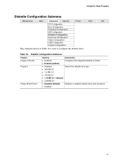
... • 720 KB 3½" • 1.44 MB 3½" (default) • 2.88 MB 3½" • Disabled (default) • Enabled Configures the integrated diskette controller. Table 16. Using the Setup Program Diskette Configuration Submenu Maintenance Main Advanced Security Power Boot Exit PCI Configuration Boot Configuration Peripheral Configuration IDE Configuration Diskette Configuration Event Log Configuration Video Configuration USB Configuration Chipset Configuration This submenu shown in Table 16 is used to configure the diskette drive. Selects the diskette drive type.
... • 720 KB 3½" • 1.44 MB 3½" (default) • 2.88 MB 3½" • Disabled (default) • Enabled Configures the integrated diskette controller. Table 16. Using the Setup Program Diskette Configuration Submenu Maintenance Main Advanced Security Power Boot Exit PCI Configuration Boot Configuration Peripheral Configuration IDE Configuration Diskette Configuration Event Log Configuration Video Configuration USB Configuration Chipset Configuration This submenu shown in Table 16 is used to configure the diskette drive. Selects the diskette drive type.

Product Guide
Page 50
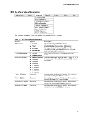
...50 USB Configuration Submenu Feature Options High Speed USB Legacy USB Support • Disabled • Enabled (default) • Disabled • Enabled (default) Description Disable this option when a USB 2.0 driver is used to configure USB features. Intel Desktop Boards D845GLLY and D845GLAD Product Guide USB Configuration Submenu Maintenance Main Advanced Security Power Boot Exit PCI Configuration Boot Configuration Peripheral Configuration IDE Configuration Diskette Configuration Event Log Configuration Video Configuration USB Configuration Chipset Configuration The menu...
...50 USB Configuration Submenu Feature Options High Speed USB Legacy USB Support • Disabled • Enabled (default) • Disabled • Enabled (default) Description Disable this option when a USB 2.0 driver is used to configure USB features. Intel Desktop Boards D845GLLY and D845GLAD Product Guide USB Configuration Submenu Maintenance Main Advanced Security Power Boot Exit PCI Configuration Boot Configuration Peripheral Configuration IDE Configuration Diskette Configuration Event Log Configuration Video Configuration USB Configuration Chipset Configuration The menu...
Product Guide
Page 52
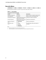
.... Intel Desktop Boards D845GLLY and D845GLAD Product Guide Security Menu Maintenance Main Advanced Security Power Boot Exit The menu shown in Table 21 is used to set . 2. alphanumeric characters. Notes: 1. Security Menu If no password entered previously: Feature Options Description Supervisor Password Is No options Reports if there is a supervisor password set. User access Level (Note 2) • Limited • No access • View Only • Full (default) Sets BIOS Setup Utility access rights for user level. Table 21. Set User Password Password...
.... Intel Desktop Boards D845GLLY and D845GLAD Product Guide Security Menu Maintenance Main Advanced Security Power Boot Exit The menu shown in Table 21 is used to set . 2. alphanumeric characters. Notes: 1. Security Menu If no password entered previously: Feature Options Description Supervisor Password Is No options Reports if there is a supervisor password set. User access Level (Note 2) • Limited • No access • View Only • Full (default) Sets BIOS Setup Utility access rights for user level. Table 21. Set User Password Password...
Product Guide
Page 54
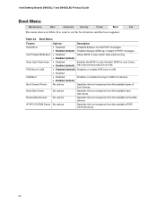
...BIOS Boot Scan User Flash Area PXE Boot to set the boot features and the boot sequence. Intel Desktop Boards D845GLLY and D845GLAD Product Guide Boot Menu Maintenance Main Advanced Security Power Boot Exit The menu shown in Table 24 is used to LAN USB Boot Boot Device Priority Hard Disk Drives Removable Devices ATAPI CD-ROM Drives Options • Disabled • Enabled (default) • Disabled • Enabled (default) • Disabled • Enabled (default) • Disabled (default) • Enabled • Disabled • Enabled (default) No options No options No options...
...BIOS Boot Scan User Flash Area PXE Boot to set the boot features and the boot sequence. Intel Desktop Boards D845GLLY and D845GLAD Product Guide Boot Menu Maintenance Main Advanced Security Power Boot Exit The menu shown in Table 24 is used to LAN USB Boot Boot Device Priority Hard Disk Drives Removable Devices ATAPI CD-ROM Drives Options • Disabled • Enabled (default) • Disabled • Enabled (default) • Disabled • Enabled (default) • Disabled (default) • Enabled • Disabled • Enabled (default) No options No options No options...

Product Guide
Page 70
... The display type is not an ATAPI device. CMOS memory may be losing power. Run Setup to access diskette drive controller. Keyboard Error Error in CMOS are not the same as the last boot. Replace the battery soon. HDC Failure Error occurred trying to protected mode during the POST, the BIOS displays an error message describing the problem. Checking NVRAM..... The system must be updated. BIOS Error Messages Error Message Explanation GA20 Error An error occurred with Gate-A20 when switching to access hard disk controller...
... The display type is not an ATAPI device. CMOS memory may be losing power. Run Setup to access diskette drive controller. Keyboard Error Error in CMOS are not the same as the last boot. Replace the battery soon. HDC Failure Error occurred trying to protected mode during the POST, the BIOS displays an error message describing the problem. Checking NVRAM..... The system must be updated. BIOS Error Messages Error Message Explanation GA20 Error An error occurred with Gate-A20 when switching to access hard disk controller...


