
Product Specification
Page 7
... Event Log Configuration Submenu 98 4.4.7 Video Configuration Submenu 99 4.5 Security Menu ...100 4.6 Power Menu ...101 4.6.1 ACPI Submenu 102 4.7 Boot Menu ...103 4.7.1 Boot Device Priority Submenu 104 4.7.2 Hard Disk Drives Submenu 105 4.7.3 Removable Devices Submenu 105 4.7.4 ATAPI CDROM Drives Submenu 106 4.8 Exit Menu ...106 5 Error Messages and Beep Codes 5.1 BIOS Error Messages 107 5.2 Port 80h POST Codes 109 5.3 Bus Initialization Checkpoints 113 5.4 Speaker ...114 5.5 BIOS Beep Codes ...115 Figures 1. Block Diagram for D815EGEW Boards with Onboard LAN Subsystem)........66...
... Event Log Configuration Submenu 98 4.4.7 Video Configuration Submenu 99 4.5 Security Menu ...100 4.6 Power Menu ...101 4.6.1 ACPI Submenu 102 4.7 Boot Menu ...103 4.7.1 Boot Device Priority Submenu 104 4.7.2 Hard Disk Drives Submenu 105 4.7.3 Removable Devices Submenu 105 4.7.4 ATAPI CDROM Drives Submenu 106 4.8 Exit Menu ...106 5 Error Messages and Beep Codes 5.1 BIOS Error Messages 107 5.2 Port 80h POST Codes 109 5.3 Bus Initialization Checkpoints 113 5.4 Speaker ...114 5.5 BIOS Beep Codes ...115 Figures 1. Block Diagram for D815EGEW Boards with Onboard LAN Subsystem)........66...

Product Specification
Page 8
... Connector 52 29. IDE Connectors ...56 38. BIOS Setup Configuration Jumper Settings (J6D1 63 46. Audio Line In Connector 49 28. Auxiliary Front Panel Power LED Connector 58 40. Wake Up Devices and Events 34 11. Fan Connector Descriptions 36 12. States for Back Panel Connectors 47 19. Supported Processors 19 5. System Memory Map 39 13. USB Connectors...47 21. Power Usage for a Dual-Colored Power LED 60 43. SCSI LED Connector (Optional 57 39. States for a D815EGEW Board 67 viii Serial Port A Connector 48 24. Power Connector...
... Connector 52 29. IDE Connectors ...56 38. BIOS Setup Configuration Jumper Settings (J6D1 63 46. Audio Line In Connector 49 28. Auxiliary Front Panel Power LED Connector 58 40. Wake Up Devices and Events 34 11. Fan Connector Descriptions 36 12. States for Back Panel Connectors 47 19. Supported Processors 19 5. System Memory Map 39 13. USB Connectors...47 21. Power Usage for a Dual-Colored Power LED 60 43. SCSI LED Connector (Optional 57 39. States for a D815EGEW Board 67 viii Serial Port A Connector 48 24. Power Connector...

Product Specification
Page 15
... Diagram for the D815EGEW Board LAN Connector OM12839 15 Primary/ Secondary IDE Processor Socket System Bus ATA-66/100 USB USB Ports (2) 815EG Chipset SDRAM Bus DIMM Banks (2) 82815G Graphics and Memory Controller Hub (GMCH) AHA Bus VGA Port Video Bus 82801BA I/O Controller Hub (ICH2) LPC Bus PCI Bus LPC I/O Controller 82802AB 4 Mbit Firmware Hub (FWH) Diskette Drive Connector Serial Port A Parallel Port PS/2 Mouse PS/2 Keyboard PCI Slot 1 PCI Slot 2 PCI Slot 3 PCI Slot 4 SM Bus Line In Line Out AC Analog Mic In Link Codec Auxiliary Line In CD-ROM Optional indicates...
... Diagram for the D815EGEW Board LAN Connector OM12839 15 Primary/ Secondary IDE Processor Socket System Bus ATA-66/100 USB USB Ports (2) 815EG Chipset SDRAM Bus DIMM Banks (2) 82815G Graphics and Memory Controller Hub (GMCH) AHA Bus VGA Port Video Bus 82801BA I/O Controller Hub (ICH2) LPC Bus PCI Bus LPC I/O Controller 82802AB 4 Mbit Firmware Hub (FWH) Diskette Drive Connector Serial Port A Parallel Port PS/2 Mouse PS/2 Keyboard PCI Slot 1 PCI Slot 2 PCI Slot 3 PCI Slot 4 SM Bus Line In Line Out AC Analog Mic In Link Codec Auxiliary Line In CD-ROM Optional indicates...

Product Specification
Page 17
...Specifications Reference Name Specification Title AC '97 Audio Codec '97 ACPI Advanced Configuration and Power Interface Specification AMI BIOS ATA/ ATAPI-5 ATX American Megatrends BIOS Specification Information Technology AT Attachment with Packet Interface - 5 (ATA/ATAPI-5) ATX Specification BIS Boot Integrity Services EPP IEEE Std 1284.1-1997 (Enhanced Parallel Port) El Torito Bootable CD-ROM Format Specification LPC MicroATX Low Pin Count Interface Specification microATX Motherboard Interface Specification Version, Revision Date, and Ownership Revision 2.1, May 1998, Intel...
...Specifications Reference Name Specification Title AC '97 Audio Codec '97 ACPI Advanced Configuration and Power Interface Specification AMI BIOS ATA/ ATAPI-5 ATX American Megatrends BIOS Specification Information Technology AT Attachment with Packet Interface - 5 (ATA/ATAPI-5) ATX Specification BIS Boot Integrity Services EPP IEEE Std 1284.1-1997 (Enhanced Parallel Port) El Torito Bootable CD-ROM Format Specification LPC MicroATX Low Pin Count Interface Specification microATX Motherboard Interface Specification Version, Revision Date, and Ownership Revision 2.1, May 1998, Intel...

Product Specification
Page 23
...-120 drive can be configured as CD-ROM drives) and ATA devices using the transfer modes listed in Table 64 on IDE bus supporting host and target throttling and transfer rates of up to each port. The IDE interfaces support the following : • ARMD-FDD (ATAPI removable media device - The IDE interfaces also support ATAPI devices (such as a boot device by setting the BIOS Setup program's Boot menu to one USB peripheral can be independently enabled. The D815EGEW board supports...
...-120 drive can be configured as CD-ROM drives) and ATA devices using the transfer modes listed in Table 64 on IDE bus supporting host and target throttling and transfer rates of up to each port. The IDE interfaces support the following : • ARMD-FDD (ATAPI removable media device - The IDE interfaces also support ATAPI devices (such as a boot device by setting the BIOS Setup program's Boot menu to one USB peripheral can be independently enabled. The D815EGEW board supports...

Product Specification
Page 36
... LAN Technology (Optional) CAUTION For Wake on LAN technology, the +5 V standby line for a processor fan or active fan heatsink. Provides +12 V DC for additional information. 36 The fan voltage can be capable of providing adequate +5 V standby current. Refer to Section 2.11.3 on page 68 for a system or chassis fan. To enable soft-off control in software, power management must be switched on or off, depending on LAN technology can damage the power supply. Failure...
... LAN Technology (Optional) CAUTION For Wake on LAN technology, the +5 V standby line for a processor fan or active fan heatsink. Provides +12 V DC for additional information. 36 The fan voltage can be capable of providing adequate +5 V standby current. Refer to Section 2.11.3 on page 68 for a system or chassis fan. To enable soft-off control in software, power management must be switched on or off, depending on LAN technology can damage the power supply. Failure...
Product Specification
Page 76
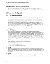
.... Intel Desktop Board D815EGEW Technical Product Specification 3.2 BIOS Flash Memory Organization The Firmware Hub (FWH) includes a 4 Mbit (512 KB) symmetrical flash memory device. PCI interrupts are automatically configured for Logical Block Addressing (LBA) and to system resources. You can automatically configure PCI devices. Autoconfiguration lets a user insert or remove PCI cards without having to ISA IRQs is stored in card. The IDE interface supports hard drives up the two IDE connectors with drives using any ATAPI devices, including CD-ROM drives, tape drives...
.... Intel Desktop Board D815EGEW Technical Product Specification 3.2 BIOS Flash Memory Organization The Firmware Hub (FWH) includes a 4 Mbit (512 KB) symmetrical flash memory device. PCI interrupts are automatically configured for Logical Block Addressing (LBA) and to system resources. You can automatically configure PCI devices. Autoconfiguration lets a user insert or remove PCI cards without having to ISA IRQs is stored in card. The IDE interface supports hard drives up the two IDE connectors with drives using any ATAPI devices, including CD-ROM drives, tape drives...

Product Specification
Page 80
... BIOS recovery mode jumper settings The Boot menu in the BIOS Setup program Contacting Intel customer support Refer to boot from an LS-120 diskette (in the non-erasable boot block area, there is configured to Table 45, page 63 Section 4.7, page 103 Section 1.2, page 16 80 Intel Desktop Board D815EGEW Technical Product Specification 3.7 Recovering BIOS Data Some types of failure can only monitor this procedure by listening to it. BIOS upgrades and the Intel Flash Memory Upgrade utility...
... BIOS recovery mode jumper settings The Boot menu in the BIOS Setup program Contacting Intel customer support Refer to boot from an LS-120 diskette (in the non-erasable boot block area, there is configured to Table 45, page 63 Section 4.7, page 103 Section 1.2, page 16 80 Intel Desktop Board D815EGEW Technical Product Specification 3.7 Recovering BIOS Data Some types of failure can only monitor this procedure by listening to it. BIOS upgrades and the Intel Flash Memory Upgrade utility...
Product Specification
Page 85
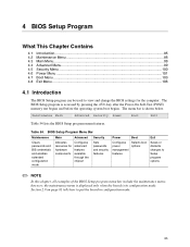
... the chipset Sets passwords and security features Power Boot Configures power management features Selects boot options Exit Saves or discards changes to put the board in configuration mode. The BIOS Setup program is shown below. The menu bar is accessed by pressing the key after the Power-On Self-Test (POST) memory test begins and before the operating system boot begins. BIOS Setup Program Menu Bar Maintenance Main Advanced Security Clears passwords and BIS credentials and enables extended configuration mode Allocates...
... the chipset Sets passwords and security features Power Boot Configures power management features Selects boot options Exit Saves or discards changes to put the board in configuration mode. The BIOS Setup program is shown below. The menu bar is accessed by pressing the key after the Power-On Self-Test (POST) memory test begins and before the operating system boot begins. BIOS Setup Program Menu Bar Maintenance Main Advanced Security Clears passwords and BIS credentials and enables extended configuration mode Allocates...

Product Specification
Page 86
...configuration mode setting information. Clears the Wired for menu screens. Displays CPU's Microcode Update Revision. Intel Desktop Board D815EGEW Technical Product Specification Table 55 lists the function keys available for Management Boot Integrity Service (BIS) credentials. Maintenance Main Advanced Security Extended Configuration Power Boot Exit The menu shown in Table 56 is for the current menu Save the current values and exits the BIOS Setup program Exits the menu 4.2 Maintenance Menu To access this menu in configuration mode. BIOS Setup Program Function Keys BIOS...
...configuration mode setting information. Clears the Wired for menu screens. Displays CPU's Microcode Update Revision. Intel Desktop Board D815EGEW Technical Product Specification Table 55 lists the function keys available for Management Boot Integrity Service (BIS) credentials. Maintenance Main Advanced Security Extended Configuration Power Boot Exit The menu shown in Table 56 is for the current menu Save the current values and exits the BIOS Setup program Exits the menu 4.2 Maintenance Menu To access this menu in configuration mode. BIOS Setup Program Function Keys BIOS...

Product Specification
Page 87
... length of clock cycles between addressing a row and addressing a column. Cache lookups are not performed. Sets extended memory configuration options to CAS# Delay SDRAM RAS# Precharge • Auto (default) • User Defined • 3 • 2 • Auto (default) • 3 • 2 • Auto (default) • 3 • 2 • Auto (default) Description User Defined allows setting memory control and video memory cache mode. This submenu becomes available when User Defined is for applications not supporting Write Combining...
... length of clock cycles between addressing a row and addressing a column. Cache lookups are not performed. Sets extended memory configuration options to CAS# Delay SDRAM RAS# Precharge • Auto (default) • User Defined • 3 • 2 • Auto (default) • 3 • 2 • Auto (default) • 3 • 2 • Auto (default) Description User Defined allows setting memory control and video memory cache mode. This submenu becomes available when User Defined is for applications not supporting Write Combining...

Product Specification
Page 88
... Main Advanced Security Power Boot Exit Table 58 describes the Main Menu. Table 58. Intel Desktop Board D815EGEW Technical Product Specification 4.3 Main Menu To access this menu, select Main on the menu bar at the top of the BIOS. Main Menu Feature BIOS Version Processor Type Processor Speed Front Side Bus Speed Cache RAM Total Memory Memory Bank 0 Memory Bank 1 Language Processor Serial Number System Time System Date Options No options No options No options No options No options No options No options • English (default) • Espanol • Disabled (default) • Enabled...
... Main Advanced Security Power Boot Exit Table 58 describes the Main Menu. Table 58. Intel Desktop Board D815EGEW Technical Product Specification 4.3 Main Menu To access this menu, select Main on the menu bar at the top of the BIOS. Main Menu Feature BIOS Version Processor Type Processor Speed Front Side Bus Speed Cache RAM Total Memory Memory Bank 0 Memory Bank 1 Language Processor Serial Number System Time System Date Options No options No options No options No options No options No options No options • English (default) • Espanol • Disabled (default) • Enabled...

Product Specification
Page 94
... the hard disk drive pre-delay. Intel Desktop Board D815EGEW Technical Product Specification 4.4.4 IDE Configuration Submenu To access this submenu, select Advanced on the menu bar, then IDE Configuration. Both enables both IDE controllers. Reports type of connected IDE device. Reports type of connected IDE device. When selected, displays the Secondary IDE Master submenu. Table 63. When selected, displays the Primary IDE Slave submenu. Reports type of connected IDE device. Secondary enables only the secondary IDE controller. Reports type of connected IDE device...
... the hard disk drive pre-delay. Intel Desktop Board D815EGEW Technical Product Specification 4.4.4 IDE Configuration Submenu To access this submenu, select Advanced on the menu bar, then IDE Configuration. Both enables both IDE controllers. Reports type of connected IDE device. Reports type of connected IDE device. When selected, displays the Secondary IDE Master submenu. Table 63. When selected, displays the Primary IDE Slave submenu. Reports type of connected IDE device. Secondary enables only the secondary IDE controller. Reports type of connected IDE device...

Product Specification
Page 95
... Feature Drive Installed Type Maximum Capacity LBA Mode Control Multi-Sector Transfers Options None • None • User • Auto (default) • CD-ROM • ATAPI Removable • Other ATAPI • IDE Removable None • Disabled (default) • Enabled • Disabled • 2 Sectors • 4 Sectors • 8 Sectors • 16 Sectors (default) Description Displays the type of the drive. Specifies the IDE configuration mode for optimum setting. Specifies number of the IDE submenus. Check the hard disk drive's specifications for IDE devices. Table...
... Feature Drive Installed Type Maximum Capacity LBA Mode Control Multi-Sector Transfers Options None • None • User • Auto (default) • CD-ROM • ATAPI Removable • Other ATAPI • IDE Removable None • Disabled (default) • Enabled • Disabled • 2 Sectors • 4 Sectors • 8 Sectors • 16 Sectors (default) Description Displays the type of the drive. Specifies the IDE configuration mode for optimum setting. Specifies number of the IDE submenus. Check the hard disk drive's specifications for IDE devices. Table...

Product Specification
Page 97
Table 65. Specifies the capacity and physical size of diskette drive A. Maintenance Main Advanced Security Power PCI Configuration Boot Configuration Peripheral Configuration IDE Configuration Diskette Configuration Event Log Configuration Video Configuration Boot Exit The submenu represented by Table 65 is used for the diskette drive. 97 Diskette Configuration Submenu Feature Diskette Controller Floppy A Diskette Write Protect Options • Disabled • Enabled (default) • Not Installed • 360 KB 5¼" • 1.2 MB 5¼" • 720 KB ...
Table 65. Specifies the capacity and physical size of diskette drive A. Maintenance Main Advanced Security Power PCI Configuration Boot Configuration Peripheral Configuration IDE Configuration Diskette Configuration Event Log Configuration Video Configuration Boot Exit The submenu represented by Table 65 is used for the diskette drive. 97 Diskette Configuration Submenu Feature Diskette Controller Floppy A Diskette Write Protect Options • Disabled • Enabled (default) • Not Installed • 360 KB 5¼" • 1.2 MB 5¼" • 720 KB ...

Product Specification
Page 100
... keyboard and mouse without a password. Reports if there is entered. The keyboard remains locked until a password is a user password set . A password is enabled, a USB aware operating system may override user password protection if used in the Security menu) are enabled, USB aware operating systems can be up to boot from the menu bar at the top of the screen. If both Legacy USB Support (in the Peripheral Configuration submenu) and Unattended Start (in conjunction with a USB keyboard...
... keyboard and mouse without a password. Reports if there is entered. The keyboard remains locked until a password is a user password set . A password is enabled, a USB aware operating system may override user password protection if used in the Security menu) are enabled, USB aware operating systems can be up to boot from the menu bar at the top of the screen. If both Legacy USB Support (in the Peripheral Configuration submenu) and Unattended Start (in conjunction with a USB keyboard...

Product Specification
Page 104
... Intel Desktop Board D815EGEW Technical Product Specification 4.7.1 Boot Device Priority Submenu To access this list will reflect as the seventh boot device. Boot Device Priority Submenu Feature 1st Boot Device 2nd Boot Device 3rd Boot Device 4th Boot Device (Note 1) Options • Removable Dev. • Hard Drive • ATAPI CD-ROM • IBA 4.0.19 Slot 010B • Disabled Description Specifies the boot sequence from the available types of the devices changes the drive lettering. While the predefined boot device types are installed on the menu bar, then Boot Devices...
... Intel Desktop Board D815EGEW Technical Product Specification 4.7.1 Boot Device Priority Submenu To access this list will reflect as the seventh boot device. Boot Device Priority Submenu Feature 1st Boot Device 2nd Boot Device 3rd Boot Device 4th Boot Device (Note 1) Options • Removable Dev. • Hard Drive • ATAPI CD-ROM • IBA 4.0.19 Slot 010B • Disabled Description Specifies the boot sequence from the available types of the devices changes the drive lettering. While the predefined boot device types are installed on the menu bar, then Boot Devices...

Product Specification
Page 109
... Shadow RAM. Boot Block Recovery Code Checkpoints Code E0 E8 E9 EA EB EC EF Description of POST Operation NMI is useful for determining the point where an error occurred. Initialize floppy drive. Onboard KBC, RTC enabled (if present). Initialize extra (Intel Recovery) Module. Booting from floppy and ATAPI device failed. Uncompress the main BIOS module. Booting from floppy failed, look for giving control to boot sector code. Error Messages and Beep Codes 5.2 Port 80h POST Codes During the POST, the BIOS...
... Shadow RAM. Boot Block Recovery Code Checkpoints Code E0 E8 E9 EA EB EC EF Description of POST Operation NMI is useful for determining the point where an error occurred. Initialize floppy drive. Onboard KBC, RTC enabled (if present). Initialize extra (Intel Recovery) Module. Booting from floppy and ATAPI device failed. Uncompress the main BIOS module. Booting from floppy failed, look for giving control to boot sector code. Error Messages and Beep Codes 5.2 Port 80h POST Codes During the POST, the BIOS...

Product Specification
Page 111
... issue keyboard controller interface test command. To enter in real mode. Going to check point # 52h.) Memory test started . Memory wrap around at 0:0. Going to display the first 64k memory size. Memory size display started . (NOT SOFT RESET) About to find out amount of memory below 1 MB memory. Going for lock-key. Shutdown successful, CPU in virtual mode for stuck key, to disable gate A20 line and disable parity/NMI. Going to adjust memory size depending...
... issue keyboard controller interface test command. To enter in real mode. Going to check point # 52h.) Memory test started . Memory wrap around at 0:0. Going to display the first 64k memory size. Memory size display started . (NOT SOFT RESET) About to find out amount of memory below 1 MB memory. Going for lock-key. Shutdown successful, CPU in virtual mode for stuck key, to disable gate A20 line and disable parity/NMI. Going to adjust memory size depending...
Product Specification
Page 115
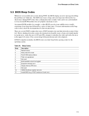
... fail. If POST completes normally, the BIOS issues one long tone followed by a series of the screen (using both monochrome and color adapters). Table 84. Error Messages and Beep Codes 5.5 BIOS Beep Codes Whenever a recoverable error occurs during POST if the video configuration fails (a faulty video card or no card installed) or if an external ROM module does not properly checksum to zero. The BIOS also issues a beep code (one short beep before passing control to the...
... fail. If POST completes normally, the BIOS issues one long tone followed by a series of the screen (using both monochrome and color adapters). Table 84. Error Messages and Beep Codes 5.5 BIOS Beep Codes Whenever a recoverable error occurs during POST if the video configuration fails (a faulty video card or no card installed) or if an external ROM module does not properly checksum to zero. The BIOS also issues a beep code (one short beep before passing control to the...


