
Product Guide
Page 4
... Installing the Desktop Board...34 Installing a Processor ...36 Removing the Processor ...38 Installing a 1 GHz Processor Fan Heatsink ...39 Removing the 1 GHz Processor Fan Heatsink ...42 Replacing the Battery ...43 Replacing the Battery on the D815EEA2 and D815EPEA2 Boards ...45 Replacing the Battery on the D815EFV and D815EPFV Boards ...46 Connecting the IDE Cable ...47 Setting the BIOS Configuration Jumper...48 Clearing the Passwords...49 3 Updating the BIOS Updating the BIOS with the Intel® Express BIOS Update Utility ...51 Updating the BIOS with the Intel® Flash Memory Update...
... Installing the Desktop Board...34 Installing a Processor ...36 Removing the Processor ...38 Installing a 1 GHz Processor Fan Heatsink ...39 Removing the 1 GHz Processor Fan Heatsink ...42 Replacing the Battery ...43 Replacing the Battery on the D815EEA2 and D815EPEA2 Boards ...45 Replacing the Battery on the D815EFV and D815EPFV Boards ...46 Connecting the IDE Cable ...47 Setting the BIOS Configuration Jumper...48 Clearing the Passwords...49 3 Updating the BIOS Updating the BIOS with the Intel® Express BIOS Update Utility ...51 Updating the BIOS with the Intel® Flash Memory Update...
Product Guide
Page 6
... Processor Fan Cable to the Processor Fan Connector ...41 Removing the Fan Heatsink...42 Removing the Battery from the D815EEA2 and D815EPEA2 Boards ...45 Removing the Battery from the D815EFV and D815EPFV Boards ...46 Connecting the IDE Cable (the D815EEA2 Board Is Shown)...47 BIOS Configuration Jumper Block Location (the D815EEA2 Board Is Shown) ...48 Connector Groups (the D815EEA2 Board Is Shown)...79 Back Panel Connectors (the D815EEA2 Board Is Shown)...80 Audio Connectors (the D815EEA2 Board Is Shown)...81 Power and Hardware Control Connectors...
... Processor Fan Cable to the Processor Fan Connector ...41 Removing the Fan Heatsink...42 Removing the Battery from the D815EEA2 and D815EPEA2 Boards ...45 Removing the Battery from the D815EFV and D815EPFV Boards ...46 Connecting the IDE Cable (the D815EEA2 Board Is Shown)...47 BIOS Configuration Jumper Block Location (the D815EEA2 Board Is Shown) ...48 Connector Groups (the D815EEA2 Board Is Shown)...79 Back Panel Connectors (the D815EEA2 Board Is Shown)...80 Audio Connectors (the D815EEA2 Board Is Shown)...81 Power and Hardware Control Connectors...

Product Guide
Page 12
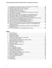
...connector SCSI hard drive activity LED connector Front panel switch/LED connector Chassis intrusion connector Alternate front panel power LED connector Chassis fan connector (fan 2, tach) BIOS configuration jumper block Battery WOL technology connector (optional) Front panel USB connector (optional) PCI bus add-in connector Front panel audio connector (optional) ATAPI-style CD-ROM connector Back panel connectors Processor fan connector (fan 1, tach) Digital Video Output (DVO) connector (D815EEA2 only) • Intel 82815E GMCH (D815EEA2 only) • Intel 82815EP MCH (D815EPEA2 only) 370-pin...
...connector SCSI hard drive activity LED connector Front panel switch/LED connector Chassis intrusion connector Alternate front panel power LED connector Chassis fan connector (fan 2, tach) BIOS configuration jumper block Battery WOL technology connector (optional) Front panel USB connector (optional) PCI bus add-in connector Front panel audio connector (optional) ATAPI-style CD-ROM connector Back panel connectors Processor fan connector (fan 1, tach) Digital Video Output (DVO) connector (D815EEA2 only) • Intel 82815E GMCH (D815EEA2 only) • Intel 82815EP MCH (D815EPEA2 only) 370-pin...
Product Guide
Page 13
... port B connector SCSI hard drive activity LED connector Front panel switch/LED connector Alternate front panel power LED connector Chassis intrusion connector Chassis fan connector (fan 2, tach) BIOS configuration jumper block WOL technology connector (optional) Front panel USB connector (optional) PCI bus add-in connector Front panel audio connector (optional) ATAPI-style CD-ROM connector Back panel connectors Processor fan connector (fan 1, tach) Digital Video Output (DVO) connector (D815EFV only) • Intel 82815E GMCH (D815EFV only) • Intel 82815EP MCH (D815EPFV only) 370-pin...
... port B connector SCSI hard drive activity LED connector Front panel switch/LED connector Alternate front panel power LED connector Chassis intrusion connector Chassis fan connector (fan 2, tach) BIOS configuration jumper block WOL technology connector (optional) Front panel USB connector (optional) PCI bus add-in connector Front panel audio connector (optional) ATAPI-style CD-ROM connector Back panel connectors Processor fan connector (fan 1, tach) Digital Video Output (DVO) connector (D815EFV only) • Intel 82815E GMCH (D815EFV only) • Intel 82815EP MCH (D815EPFV only) 370-pin...
Product Guide
Page 18
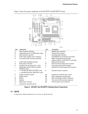
... back panel connectors and the other port is accessible through a CNR add-in ports. USB Support The desktop boards have a time-of standard software drivers written to be compatible with serialized IRQ support for PCI systems PS/2-style mouse and keyboard interfaces Interface for one 1.2 MB, 1.44 MB, or 2.88 MB diskette drive Intelligent power management, including a programmable wake up to either the SMSC LPC47M132 or optional SMSC LPC47M142 LPC bus I/O controller...
... back panel connectors and the other port is accessible through a CNR add-in ports. USB Support The desktop boards have a time-of standard software drivers written to be compatible with serialized IRQ support for PCI systems PS/2-style mouse and keyboard interfaces Interface for one 1.2 MB, 1.44 MB, or 2.88 MB diskette drive Intelligent power management, including a programmable wake up to either the SMSC LPC47M132 or optional SMSC LPC47M142 LPC bus I/O controller...
Product Guide
Page 20
... Web site: http://support.intel.com/support/motherboards/desktop BIOS The BIOS provides the Power-On Self-Test (POST), the BIOS Setup program, the PCI and IDE auto-configuration utilities, and the video BIOS. PCI Auto Configuration If you install a PCI add-in board in your computer. You can be upgraded by specifying manual configuration in board. Audio drivers and utilities are connected to this output. You do not need to -noise) ratio: > 90 dB Power management support for APM 1.2 and ACPI 2.0 (driver dependent) 3-D stereo enhancement...
... Web site: http://support.intel.com/support/motherboards/desktop BIOS The BIOS provides the Power-On Self-Test (POST), the BIOS Setup program, the PCI and IDE auto-configuration utilities, and the video BIOS. PCI Auto Configuration If you install a PCI add-in board in your computer. You can be upgraded by specifying manual configuration in board. Audio drivers and utilities are connected to this output. You do not need to -noise) ratio: > 90 dB Power management support for APM 1.2 and ACPI 2.0 (driver dependent) 3-D stereo enhancement...
Product Guide
Page 21
... software configurable Intel® 82562ET Platform LAN Connect Device The Intel 82562ET LAN component provides an interface to the back panel RJ-45 connector with status indicator LEDs Full driver compatibility Advanced Power Management (APM) support Programmable transit threshold Configurable EEPROM that restrict whether the BIOS Setup program can be accessed and who can enter either the supervisor password or the user password to view and change all Setup options. the LAN subsystem is booted. Features include 32-bit...
... software configurable Intel® 82562ET Platform LAN Connect Device The Intel 82562ET LAN component provides an interface to the back panel RJ-45 connector with status indicator LEDs Full driver compatibility Advanced Power Management (APM) support Programmable transit threshold Configurable EEPROM that restrict whether the BIOS Setup program can be accessed and who can enter either the supervisor password or the user password to view and change all Setup options. the LAN subsystem is booted. Features include 32-bit...

Product Guide
Page 23
... the Wake on LAN technology connector on the desktop board. The desktop board standby power indicator, shown in memory. If the system has a dual-colored power LED on the PCI bus connectors). Network adapters that have power, even when the computer appears to support multiple wake events from the PCI and/or USB buses exceeds power supply capacity, the desktop board may lose register settings stored in Figure 3, is indicated by a wake-up connector. Instantly Available technology enables the board to enter the ACPI...
... the Wake on LAN technology connector on the desktop board. The desktop board standby power indicator, shown in memory. If the system has a dual-colored power LED on the PCI bus connectors). Network adapters that have power, even when the computer appears to support multiple wake events from the PCI and/or USB buses exceeds power supply capacity, the desktop board may lose register settings stored in Figure 3, is indicated by a wake-up connector. Instantly Available technology enables the board to enter the ACPI...
Product Guide
Page 25
... from its power source and from any telecommunications links, networks, or modems before you open the computer or perform any of the computer chassis. 2 Installing and Replacing Desktop Board Components This chapter tells you how to Install and remove memory Install and remove the AGP card retention mechanism (included) Install and remove AGP and GPA cards Install the I/O shield Install the desktop board Install and remove the processor Replace the battery Connect the IDE cable Set the BIOS configuration jumper Before You...
... from its power source and from any telecommunications links, networks, or modems before you open the computer or perform any of the computer chassis. 2 Installing and Replacing Desktop Board Components This chapter tells you how to Install and remove memory Install and remove the AGP card retention mechanism (included) Install and remove AGP and GPA cards Install the I/O shield Install the desktop board Install and remove the processor Replace the battery Connect the IDE cable Set the BIOS configuration jumper Before You...
Product Guide
Page 48
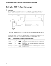
Intel Desktop Boards D815EEA2, D815EPEA2, D815EFV, and D815EPFV Product Guide Setting the BIOS Configuration Jumper CAUTION Always turn off the power and unplug the power cord from the computer before changing the jumper. Table 7 shows the jumper settings for booting. The maintenance menu is required. 3 1 3 1 48 After the POST runs, Setup runs automatically. BIOS Configuration Jumper Block Location (the D815EEA2 Board Is Shown) This three-pin jumper block, shown in Figure 26, enables all desktop board configurations to recover the BIOS configuration. Moving...
Intel Desktop Boards D815EEA2, D815EPEA2, D815EFV, and D815EPFV Product Guide Setting the BIOS Configuration Jumper CAUTION Always turn off the power and unplug the power cord from the computer before changing the jumper. Table 7 shows the jumper settings for booting. The maintenance menu is required. 3 1 3 1 48 After the POST runs, Setup runs automatically. BIOS Configuration Jumper Block Location (the D815EEA2 Board Is Shown) This three-pin jumper block, shown in Figure 26, enables all desktop board configurations to recover the BIOS configuration. Moving...

Product Guide
Page 49
.... Place the jumper on pins 1-2 as shown below . 3 1 13. Press and Setup displays a pop-up screen requesting that the desktop board is set to the computer. Turn off all peripheral devices connected to normal mode. 1. Disconnect the computer's power cord from the ac power source. 11. Remove the computer cover. 4. Replace the cover, plug in the computer and the configuration jumper block is installed in the computer, turn on the computer...
.... Place the jumper on pins 1-2 as shown below . 3 1 13. Press and Setup displays a pop-up screen requesting that the desktop board is set to the computer. Turn off all peripheral devices connected to normal mode. 1. Disconnect the computer's power cord from the ac power source. 11. Remove the computer cover. 4. Replace the cover, plug in the computer and the configuration jumper block is installed in the computer, turn on the computer...

Product Guide
Page 58
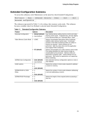
... Wired for menu screens. Clear All Passwords Clear BIS Credentials • Yes (default) • No Extended Configuration CPU Microcode Update Revision CPU Stepping Signature No options No options No options 58 Invokes the Extended Configuration submenu. Intel Desktop Boards D815EEA2, D815EPEA2, D815EFV, and D815EPFV Product Guide Table 9 shows the function keys available for Management Boot Integrity Service (BIS) credentials. See page 48 for the current menu Save the current values and exits the BIOS Setup...
... Wired for menu screens. Clear All Passwords Clear BIS Credentials • Yes (default) • No Extended Configuration CPU Microcode Update Revision CPU Stepping Signature No options No options No options 58 Invokes the Extended Configuration submenu. Intel Desktop Boards D815EEA2, D815EPEA2, D815EFV, and D815EPFV Product Guide Table 9 shows the function keys available for Management Boot Integrity Service (BIS) credentials. See page 48 for the current menu Save the current values and exits the BIOS Setup...
Product Guide
Page 59
...; Default (default) • User-Defined Description User Defined allows setting memory control and video memory cache mode. Cache lookups are not performed. Both the video driver and the application must support Write Combining. Selects UnCacheable (UC) video memory cache mode. This setting identifies the video memory range as required. Cache lookups are not performed. Maintenance Main Advanced Security Power Boot Exit Extended Configuration The submenu represented by the processor. If selected here, will also display...
...; Default (default) • User-Defined Description User Defined allows setting memory control and video memory cache mode. Cache lookups are not performed. Both the video driver and the application must support Write Combining. Selects UnCacheable (UC) video memory cache mode. This setting identifies the video memory range as required. Cache lookups are not performed. Maintenance Main Advanced Security Power Boot Exit Extended Configuration The submenu represented by the processor. If selected here, will also display...

Product Guide
Page 60
... screen. Intel Desktop Boards D815EEA2, D815EPEA2, D815EFV, and D815EPFV Product Guide Main Menu To access this menu, select Main on the menu bar at the top of RAM in the memory banks. This menu reports processor and memory information and is installed.) • Enabled Hour, minute, and second Day of the BIOS. Feature BIOS Version Processor Type Processor Speed System Bus Frequency Cache RAM Total Memory Memory Bank 0 Memory Bank 1 Memory Bank 2 Language Processor Serial Number System Time System Date Main Menu Options No options No options No options No options...
... screen. Intel Desktop Boards D815EEA2, D815EPEA2, D815EFV, and D815EPFV Product Guide Main Menu To access this menu, select Main on the menu bar at the top of RAM in the memory banks. This menu reports processor and memory information and is installed.) • Enabled Hour, minute, and second Day of the BIOS. Feature BIOS Version Processor Type Processor Speed System Bus Frequency Cache RAM Total Memory Memory Bank 0 Memory Bank 1 Memory Bank 2 Language Processor Serial Number System Time System Date Main Menu Options No options No options No options No options...
Product Guide
Page 66
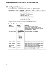
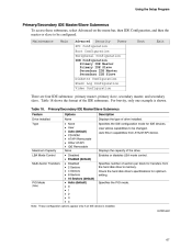
...Disabled (default) Specifies the hard disk drive pre-delay. • 3 Seconds • 6 Seconds • 9 Seconds • 12 Seconds • 15 Seconds • 21 Seconds • 30 Seconds Primary IDE Master Primary IDE Slave Secondary IDE Master No options No options No options Reports type of connected IDE device. Maintenance Main Advanced Security Power Boot Exit PCI Configuration Boot Configuration Peripheral Configuration IDE Configuration Diskette Configuration Event Log Configuration Video Configuration The menu represented in Table 17 is used to configure IDE device options...
...Disabled (default) Specifies the hard disk drive pre-delay. • 3 Seconds • 6 Seconds • 9 Seconds • 12 Seconds • 15 Seconds • 21 Seconds • 30 Seconds Primary IDE Master Primary IDE Slave Secondary IDE Master No options No options No options Reports type of connected IDE device. Maintenance Main Advanced Security Power Boot Exit PCI Configuration Boot Configuration Peripheral Configuration IDE Configuration Diskette Configuration Event Log Configuration Video Configuration The menu represented in Table 17 is used to configure IDE device options...
Product Guide
Page 67
... • User • Auto (default) • CD-ROM • ATAPI Removable • Other ATAPI • IDE Removable None • Disabled • Enabled (default Disabled 2 Sectors 4 Sectors 8 Sectors 16 Sectors (default) Auto (default) 0 1 2 3 4 Description Displays the type of the IDE submenus. Auto fills-in capabilities from the hard disk drive to memory. Maximum Capacity LBA Mode Control Multi-Sector Transfers Displays the capacity of sectors per block for transfers from ATA/ATAPI device. Maintenance Main Advanced Security Power Boot Exit PCI Configuration Boot Configuration...
... • User • Auto (default) • CD-ROM • ATAPI Removable • Other ATAPI • IDE Removable None • Disabled • Enabled (default Disabled 2 Sectors 4 Sectors 8 Sectors 16 Sectors (default) Auto (default) 0 1 2 3 4 Description Displays the type of the IDE submenus. Auto fills-in capabilities from the hard disk drive to memory. Maximum Capacity LBA Mode Control Multi-Sector Transfers Displays the capacity of sectors per block for transfers from ATA/ATAPI device. Maintenance Main Advanced Security Power Boot Exit PCI Configuration Boot Configuration...
Product Guide
Page 74
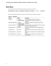
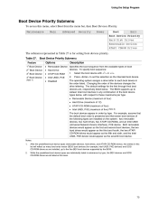
Enabled displays OEM graphic instead of POST messages. Intel® Rapid BIOS Boot Scan User Flash Area Boot Device Priority Hard Disk Drives Removeable Devices ATAPI CDROM Drives • Disabled • Enabled (default) • Disabled (default) Enables the BIOS to scan the flash memory for user binary files that are executed at the top of the screen. Table 26. Specifies the boot sequence from the available removable devices. Enables the computer to set the boot features and the boot sequence. Intel Desktop Boards D815EEA2, D815EPEA2, D815EFV, and D815EPFV Product Guide Boot Menu...
Enabled displays OEM graphic instead of POST messages. Intel® Rapid BIOS Boot Scan User Flash Area Boot Device Priority Hard Disk Drives Removeable Devices ATAPI CDROM Drives • Disabled • Enabled (default) • Disabled (default) Enables the BIOS to scan the flash memory for user binary files that are executed at the top of the screen. Table 26. Specifies the boot sequence from the available removable devices. Enables the computer to set the boot features and the boot sequence. Intel Desktop Boards D815EEA2, D815EPEA2, D815EFV, and D815EPFV Product Guide Boot Menu...
Product Guide
Page 75
... the default boot order is for the first through final boot devices are installed on the system: two removable devices, two hard drives, two ATAPI CD-ROMs, and an Intel UNDI (Universal Network Device Interface), PXE device. Maintenance Main Advanced Security Power Boot Exit Boot Device Priority Hard Disk Drives Removeable Devices ATAPI CDROM Drives The submenu represented in any combination of the boot device types below . Table 27. The BIOS supports up to each boot device in order by the BIOS. Both removable devices...
... the default boot order is for the first through final boot devices are installed on the system: two removable devices, two hard drives, two ATAPI CD-ROMs, and an Intel UNDI (Universal Network Device Interface), PXE device. Maintenance Main Advanced Security Power Boot Exit Boot Device Priority Hard Disk Drives Removeable Devices ATAPI CDROM Drives The submenu represented in any combination of the boot device types below . Table 27. The BIOS supports up to each boot device in order by the BIOS. Both removable devices...
Product Guide
Page 77
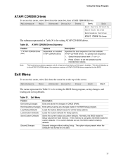
... boot device of this memory is installed. Using the Setup Program ATAPI CDROM Drives To access this menu, select Boot from flash memory. To specify boot sequence: 1. 2. Press to four ATAPI CD-ROM drives, the maximum number of the screen. Note: This boot device submenu appears only if at the top of ATAPI CD-ROM drives supported by the BIOS. Loads the custom defaults for all the Setup options. Saves the current values as the intended boot device...
... boot device of this memory is installed. Using the Setup Program ATAPI CDROM Drives To access this menu, select Boot from flash memory. To specify boot sequence: 1. 2. Press to four ATAPI CD-ROM drives, the maximum number of the screen. Note: This boot device submenu appears only if at the top of ATAPI CD-ROM drives supported by the BIOS. Loads the custom defaults for all the Setup options. Saves the current values as the intended boot device...
Product Guide
Page 80
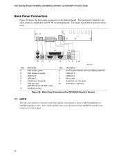
... PS/2 keyboard, purple USB port 0 USB port 1 Parallel port, burgundy VGA port, blue (D815EEA2 and D815EFV only) Serial port A, teal H I J K L M RJ-45 LAN connector with LED display (optional) USB port 2 USB port 3 Mic in, pink Audio line out, lime green Audio line in compliance with PC 99 recommendations. Poor audio quality may occur if passive (non-amplified) speakers are color-coded in , light blue Figure 28. The back panel connectors are connected to power either headphones or amplified speakers only.
... PS/2 keyboard, purple USB port 0 USB port 1 Parallel port, burgundy VGA port, blue (D815EEA2 and D815EFV only) Serial port A, teal H I J K L M RJ-45 LAN connector with LED display (optional) USB port 2 USB port 3 Mic in, pink Audio line out, lime green Audio line in compliance with PC 99 recommendations. Poor audio quality may occur if passive (non-amplified) speakers are color-coded in , light blue Figure 28. The back panel connectors are connected to power either headphones or amplified speakers only.


