
Product Guide
Page 4
... Desktop Board...34 Installing a Processor ...36 Removing the Processor ...38 Installing a 1 GHz Processor Fan Heatsink ...39 Removing the 1 GHz Processor Fan Heatsink ...42 Replacing the Battery ...43 Replacing the Battery on the D815EEA2 and D815EPEA2 Boards ...45 Replacing the Battery on the D815EFV and D815EPFV Boards ...46 Connecting the IDE Cable ...47 Setting the BIOS Configuration Jumper...
... Desktop Board...34 Installing a Processor ...36 Removing the Processor ...38 Installing a 1 GHz Processor Fan Heatsink ...39 Removing the 1 GHz Processor Fan Heatsink ...42 Replacing the Battery ...43 Replacing the Battery on the D815EEA2 and D815EPEA2 Boards ...45 Replacing the Battery on the D815EFV and D815EPFV Boards ...46 Connecting the IDE Cable ...47 Setting the BIOS Configuration Jumper...
Product Guide
Page 6
Intel Desktop Boards D815EEA2, D815EPEA2, D815EFV, and D815EPFV Product Guide 16. 17. 18. 19. 20. 21. 22. 23. 24. 25. 26. 27. 28. 29. 30. 31. Front Panel Connectors (the D815EEA2 Board Is Shown) ...85 Tables 1. 2. 3. 4. 5. 6. 7. 8. 9. 10. 11. 12. 13. 14. 15. 16. 17. 18. 19. 20. 21. 22. 23. 24. Board... and Memory Module Combinations...16 RJ-45 LAN Connector LEDs ...22 Jumper Settings for the D815EFV and D815EPFV Boards...84 33. Add-in Board and Peripheral Interface Connectors for the D815EEA2 and D815EPEA2 Boards ...83 32. Connecting the Processor Fan Cable to the Processor Fan...
Intel Desktop Boards D815EEA2, D815EPEA2, D815EFV, and D815EPFV Product Guide 16. 17. 18. 19. 20. 21. 22. 23. 24. 25. 26. 27. 28. 29. 30. 31. Front Panel Connectors (the D815EEA2 Board Is Shown) ...85 Tables 1. 2. 3. 4. 5. 6. 7. 8. 9. 10. 11. 12. 13. 14. 15. 16. 17. 18. 19. 20. 21. 22. 23. 24. Board... and Memory Module Combinations...16 RJ-45 LAN Connector LEDs ...22 Jumper Settings for the D815EFV and D815EPFV Boards...84 33. Add-in Board and Peripheral Interface Connectors for the D815EEA2 and D815EPEA2 Boards ...83 32. Connecting the Processor Fan Cable to the Processor Fan...
Product Guide
Page 25
... (included) Install and remove AGP and GPA cards Install the I/O shield Install the desktop board Install and remove the processor Replace the battery Connect the IDE cable Set the BIOS configuration jumper Before You Begin ✏ NOTE Before you install the desktop board in a chassis, see Appendix B for using an anti-static wrist strap and a conductive...
... (included) Install and remove AGP and GPA cards Install the I/O shield Install the desktop board Install and remove the processor Replace the battery Connect the IDE cable Set the BIOS configuration jumper Before You Begin ✏ NOTE Before you install the desktop board in a chassis, see Appendix B for using an anti-static wrist strap and a conductive...
Product Guide
Page 48
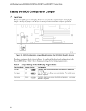
After the POST runs, Setup runs automatically. Intel Desktop Boards D815EEA2, D815EPEA2, D815EFV, and D815EPFV Product Guide Setting the BIOS Configuration Jumper CAUTION Always turn off the power and unplug the power cord from the computer before changing the jumper. Table 7 shows the jumper settings for booting. The maintenance menu is required. 3 1 3 1 48 The BIOS attempts to be done in...
After the POST runs, Setup runs automatically. Intel Desktop Boards D815EEA2, D815EPEA2, D815EFV, and D815EPFV Product Guide Setting the BIOS Configuration Jumper CAUTION Always turn off the power and unplug the power cord from the computer before changing the jumper. Table 7 shows the jumper settings for booting. The maintenance menu is required. 3 1 3 1 48 The BIOS attempts to be done in...
Product Guide
Page 49
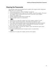
... and allow it to normal mode. 1. The computer starts the Setup program. Remove the computer cover. 12. Installing and Replacing Desktop Board Components Clearing the Passwords This procedure assumes that you confirm clearing the password. Select Yes and press . Disconnect the computer's power...values and exit Setup. 10. Observe the precautions in the computer and the configuration jumper block is set to boot. 7. Press to the computer. Press and Setup displays a pop-up screen requesting that the desktop board is installed in "Before You Begin" (see Figure 26). 5.
... and allow it to normal mode. 1. The computer starts the Setup program. Remove the computer cover. 12. Installing and Replacing Desktop Board Components Clearing the Passwords This procedure assumes that you confirm clearing the password. Select Yes and press . Disconnect the computer's power...values and exit Setup. 10. Observe the precautions in the computer and the configuration jumper block is set to boot. 7. Press to the computer. Press and Setup displays a pop-up screen requesting that the desktop board is installed in "Before You Begin" (see Figure 26). 5.
Product Guide
Page 55
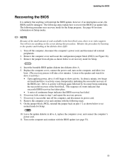
... Replace the computer cover, connect the power cord, turn off the computer, disconnect the computer's power cord, and disconnect all pins as shown below to set normal mode for Setup. 3 1 4. Listen to the speaker and watch for drive A activity.) • Upon applying power, drive A will not ...see Figure 26). 3. If recovery fails, return to set recovery mode for Setup. 3 1 10. On the jumper block (J9G2), reinstall the jumper back on the computer, and allow it to show activity. Turn on Setup modes. ✏ NOTE Because of ...
... Replace the computer cover, connect the power cord, turn off the computer, disconnect the computer's power cord, and disconnect all pins as shown below to set normal mode for Setup. 3 1 4. Listen to the speaker and watch for drive A activity.) • Upon applying power, drive A will not ...see Figure 26). 3. If recovery fails, return to set recovery mode for Setup. 3 1 10. On the jumper block (J9G2), reinstall the jumper back on the computer, and allow it to show activity. Turn on Setup modes. ✏ NOTE Because of ...
Product Guide
Page 57
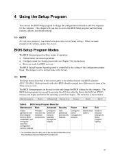
...how to access the BIOS Setup program and lists Setup features, options, and default settings. ✏ NOTE For reference purposes, you make changes to the settings, update this section apply to the desktop boards with other BIOS identifiers might have differences in this record. 4 Using the Setup ...Main Allocates resources for BIOS recovery The BIOS Setup Program Operating mode is set to the Intel World Wide Web site at the factory. ✏ NOTE The Setup menus described in some of the configuration jumper block. Maintenance Table 8. The BIOS Setup program is shown below.
...how to access the BIOS Setup program and lists Setup features, options, and default settings. ✏ NOTE For reference purposes, you make changes to the settings, update this section apply to the desktop boards with other BIOS identifiers might have differences in this record. 4 Using the Setup ...Main Allocates resources for BIOS recovery The BIOS Setup Program Operating mode is set to the Intel World Wide Web site at the factory. ✏ NOTE The Setup menus described in some of the configuration jumper block. Maintenance Table 8. The BIOS Setup program is shown below.


