
Technical Product Specification
Page 5
... Technical Product Specification (TPS) specifies the board layout, components, connectors, power and environmental requirements, and the BIOS for general audiences. What This Document Contains Chapter 1 2 3 4 5 Description A description of the hardware used on Intel NUC Board D54250WYB and Intel NUC Board D34010WYB A map of the resources of the Intel NUC Board The features supported by the BIOS Setup program A description of the BIOS error messages, beep codes, and POST codes Regulatory compliance and battery disposal...
... Technical Product Specification (TPS) specifies the board layout, components, connectors, power and environmental requirements, and the BIOS for general audiences. What This Document Contains Chapter 1 2 3 4 5 Description A description of the hardware used on Intel NUC Board D54250WYB and Intel NUC Board D34010WYB A map of the resources of the Intel NUC Board The features supported by the BIOS Setup program A description of the BIOS error messages, beep codes, and POST codes Regulatory compliance and battery disposal...
Technical Product Specification
Page 8
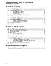
... of BIOS Features 3.1 Introduction 57 3.2 BIOS Flash Memory Organization 58 3.3 System Management BIOS (SMBIOS 58 3.4 Legacy USB Support 58 3.5 BIOS Updates 59 3.5.1 Language Support 59 3.5.2 Custom Splash Screen 60 3.6 BIOS Recovery 60 3.7 Boot Options 61 3.7.1 Network Boot 61 3.7.2 Booting Without Attached Devices 61 3.7.3 Changing the Default Boot Device During POST 61 3.7.4 Power Button Menu 62 3.8 Hard Disk Drive Password Security Feature 63 3.9 BIOS Security Features 64 4 Error Messages and Blink Codes 4.1 Front-panel Power LED Blink Codes 65 4.2 BIOS Error Messages...
... of BIOS Features 3.1 Introduction 57 3.2 BIOS Flash Memory Organization 58 3.3 System Management BIOS (SMBIOS 58 3.4 Legacy USB Support 58 3.5 BIOS Updates 59 3.5.1 Language Support 59 3.5.2 Custom Splash Screen 60 3.6 BIOS Recovery 60 3.7 Boot Options 61 3.7.1 Network Boot 61 3.7.2 Booting Without Attached Devices 61 3.7.3 Changing the Default Boot Device During POST 61 3.7.4 Power Button Menu 62 3.8 Hard Disk Drive Password Security Feature 63 3.9 BIOS Security Features 64 4 Error Messages and Blink Codes 4.1 Front-panel Power LED Blink Codes 65 4.2 BIOS Error Messages...

Technical Product Specification
Page 9
... of Pressing the Power Switch 31 10. Memory Channel and SO-DIMM Configuration 20 5. 4-Pin 3.5 mm (1/8 inch) Audio Jack Pin Out 26 6. Major Board Components (Top 13 2. Major Board Components (Bottom 15 3. Location of the Standby Power LED 35 9. Front Panel Connectors 38 10. Back Panel Connectors 38 11. Header (Top 39 12. Connection Diagram for Internal USB 2.0 Dual-Port Header (2.0 mm Pitch 48 15. Connection Diagram for Front Panel Header (2.0 mm Pitch 46 14. Localized High Temperature Zones 54 Tables...
... of Pressing the Power Switch 31 10. Memory Channel and SO-DIMM Configuration 20 5. 4-Pin 3.5 mm (1/8 inch) Audio Jack Pin Out 26 6. Major Board Components (Top 13 2. Major Board Components (Bottom 15 3. Location of the Standby Power LED 35 9. Front Panel Connectors 38 10. Back Panel Connectors 38 11. Header (Top 39 12. Connection Diagram for Internal USB 2.0 Dual-Port Header (2.0 mm Pitch 48 15. Connection Diagram for Front Panel Header (2.0 mm Pitch 46 14. Localized High Temperature Zones 54 Tables...

Technical Product Specification
Page 10
... BIOS Recovery 60 28. Environmental Specifications 56 27. Boot Device Menu Options 61 29. PCI Express Full-/Half-Mini Card Connector 42 15. Fan Header Current Capability 53 24. Master Key and User Hard Drive Password Functions 63 30. BIOS Error Messages 65 33. Regulatory Compliance Marks 73 x Supervisor and User Password Functions 64 31. Safety Standards 67 34. System ID / Custom Solutions Header (2.0 mm Pitch 44 19. 12-24 V Internal Power Supply Connector 45 20. Acceptable Drives...
... BIOS Recovery 60 28. Environmental Specifications 56 27. Boot Device Menu Options 61 29. PCI Express Full-/Half-Mini Card Connector 42 15. Fan Header Current Capability 53 24. Master Key and User Hard Drive Password Functions 63 30. BIOS Error Messages 65 33. Regulatory Compliance Marks 73 x Supervisor and User Password Functions 64 31. Safety Standards 67 34. System ID / Custom Solutions Header (2.0 mm Pitch 44 19. 12-24 V Internal Power Supply Connector 45 20. Acceptable Drives...
Technical Product Specification
Page 11
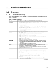
... Intel NUC Board D54250WYB and Intel NUC Board D34010WYB. 1 Product Description 1.1 Overview 1.1.1 Feature Summary Table 1 summarizes the major features of system memory with two SO-DIMMs using 4 Gb memory technology • Support for non-ECC memory • Support for 1.35 V low voltage JEDEC memory only • Integrated graphics support for processors with Intel® Graphics Technology: ― One Mini High Definition Multimedia Interface* (Mini HDMI*) back panel connector ― One Mini DisplayPort* back panel connector • Intel...
... Intel NUC Board D54250WYB and Intel NUC Board D34010WYB. 1 Product Description 1.1 Overview 1.1.1 Feature Summary Table 1 summarizes the major features of system memory with two SO-DIMMs using 4 Gb memory technology • Support for non-ECC memory • Support for 1.35 V low voltage JEDEC memory only • Integrated graphics support for processors with Intel® Graphics Technology: ― One Mini High Definition Multimedia Interface* (Mini HDMI*) back panel connector ― One Mini DisplayPort* back panel connector • Intel...

Technical Product Specification
Page 12
... Technology LAN Support • One PCI Express Half-Mini Card connector • One PCI Express Full-Mini Card connector • Intel® BIOS resident in the Serial Peripheral Interface (SPI) Flash device • Support for Advanced Configuration and Power Interface (ACPI), Plug and Play, and System Management BIOS (SMBIOS) • Support for PCI Express* • Suspend to RAM support • Wake on PCI Express, LAN, front panel, Consumer Infrared (CIR), and USB ports Gigabit (10/100/1000 Mb/s) LAN subsystem using the Intel® I218V Gigabit Ethernet Controller...
... Technology LAN Support • One PCI Express Half-Mini Card connector • One PCI Express Full-Mini Card connector • Intel® BIOS resident in the Serial Peripheral Interface (SPI) Flash device • Support for Advanced Configuration and Power Interface (ACPI), Plug and Play, and System Management BIOS (SMBIOS) • Support for PCI Express* • Suspend to RAM support • Wake on PCI Express, LAN, front panel, Consumer Infrared (CIR), and USB ports Gigabit (10/100/1000 Mb/s) LAN subsystem using the Intel® I218V Gigabit Ethernet Controller...
Technical Product Specification
Page 18
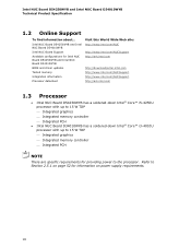
... 15 W TDP Integrated graphics Integrated memory controller Integrated PCH NOTE There are specific requirements for information on power supply requirements. 18 Intel NUC Board D54250WYB and Intel NUC Board D34010WYB Technical Product Specification 1.2 Online Support To find information about... Intel NUC Board D54250WYB and Intel NUC Board D34010WYB Intel NUC Board Support Available configurations for Intel NUC Board D54250WYB and Intel NUC Board D34010WYB BIOS and driver updates Tested memory Integration information Processor datasheet Visit this World Wide...
... 15 W TDP Integrated graphics Integrated memory controller Integrated PCH NOTE There are specific requirements for information on power supply requirements. 18 Intel NUC Board D54250WYB and Intel NUC Board D34010WYB Technical Product Specification 1.2 Online Support To find information about... Intel NUC Board D54250WYB and Intel NUC Board D34010WYB Intel NUC Board Support Available configurations for Intel NUC Board D54250WYB and Intel NUC Board D34010WYB BIOS and driver updates Tested memory Integration information Processor datasheet Visit this World Wide...
Technical Product Specification
Page 19
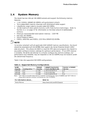
... for optimum performance. Table 4 lists the supported SO-DIMM configurations. Tested Memory Refer to correctly configure the memory settings, but performance and reliability may be populated with 4 Gb memory technology). If non-SPD memory is installed, the BIOS will attempt to : http://www.intel.com/NUCSupport 19 Table 4. Product Description 1.4 System Memory The board has two 204-pin SO-DIMM sockets and support the following memory features: • 1.35...
... for optimum performance. Table 4 lists the supported SO-DIMM configurations. Tested Memory Refer to correctly configure the memory settings, but performance and reliability may be populated with 4 Gb memory technology). If non-SPD memory is installed, the BIOS will attempt to : http://www.intel.com/NUCSupport 19 Table 4. Product Description 1.4 System Memory The board has two 204-pin SO-DIMM sockets and support the following memory features: • 1.35...
Technical Product Specification
Page 22
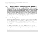
... HDMI display interface connecting the processor and display devices utilizes transition minimized differential signaling (TMDS) to http://www.displayport.org 22 The Mini DisplayPort interface supports the 1.2 specification. It can carry high quality multi-channel audio data and all standard and high-definition consumer electronics video formats. DisplayPort is a digital communication interface that support DisplayPort 1.2 and allow for display connections between PCs and monitors, projectors, and TV displays. Intel NUC Board D54250WYB...
... HDMI display interface connecting the processor and display devices utilizes transition minimized differential signaling (TMDS) to http://www.displayport.org 22 The Mini DisplayPort interface supports the 1.2 specification. It can carry high quality multi-channel audio data and all standard and high-definition consumer electronics video formats. DisplayPort is a digital communication interface that support DisplayPort 1.2 and allow for display connections between PCs and monitors, projectors, and TV displays. Intel NUC Board D54250WYB...
Technical Product Specification
Page 25
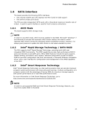
.... Software components include an Option ROM for pre-boot configuration and boot functionality, a Microsoft Windows compatible driver, and a user interface for configuration and management of the RAID capability of the PCH. 1.6.3 Intel® Smart Response Technology Intel® Smart Response Technology is always good practice to update the AHCI drivers to use AHCI mode, AHCI must first enable RAID in the BIOS. For more information on all SATA ports. Microsoft* Windows* 7 and Windows 8 includes the necessary AHCI drivers without the need to device connections. 1.6.1 AHCI Mode...
.... Software components include an Option ROM for pre-boot configuration and boot functionality, a Microsoft Windows compatible driver, and a user interface for configuration and management of the RAID capability of the PCH. 1.6.3 Intel® Smart Response Technology Intel® Smart Response Technology is always good practice to update the AHCI drivers to use AHCI mode, AHCI must first enable RAID in the BIOS. For more information on all SATA ports. Microsoft* Windows* 7 and Windows 8 includes the necessary AHCI drivers without the need to device connections. 1.6.1 AHCI Mode...
Technical Product Specification
Page 27
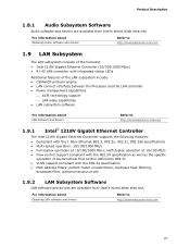
... mode 1.9.2 LAN Subsystem Software LAN software and drivers are available from Intel's World Wide Web site. Half-duplex operation at 10/100 Mb/s • Flow control support compliant with the 802.3X specification as well as the specific operation of the LAN subsystem include: • CSMA/CD protocol engine • LAN connect interface between the Processor and the LAN controller • Power management capabilities ACPI technology support LAN wake capabilities • LAN...
... mode 1.9.2 LAN Subsystem Software LAN software and drivers are available from Intel's World Wide Web site. Half-duplex operation at 10/100 Mb/s • Flow control support compliant with the 802.3X specification as well as the specific operation of the LAN subsystem include: • CSMA/CD protocol engine • LAN connect interface between the Processor and the LAN controller • Power management capabilities ACPI technology support LAN wake capabilities • LAN...

Technical Product Specification
Page 31
...; Support for multiple wake-up (ACPI G0 - The use of individual devices, add-in boards (some add-in boards may require an ACPI-aware driver), video displays, and hard disk drives • Methods for ...the system enters this board requires an operating system that enables the operating system to power-off ) Sleep (ACPI G1 - working state) On (ACPI G0 - Table 9. ACPI features include: • Plug and Play (including bus and device enumeration) • Power management control of ACPI with...
...; Support for multiple wake-up (ACPI G0 - The use of individual devices, add-in boards (some add-in boards may require an ACPI-aware driver), video displays, and hard disk drives • Methods for ...the system enters this board requires an operating system that enables the operating system to power-off ) Sleep (ACPI G1 - working state) On (ACPI G0 - Table 9. ACPI features include: • Plug and Play (including bus and device enumeration) • Power management control of ACPI with...
Technical Product Specification
Page 34
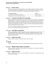
.... 1.11.2.4 Wake from USB USB bus activity wakes the computer from an ACPI S3 state. While in the BIOS Setup program's Boot menu. NOTE Wake from USB requires the use of Instantly Available PC technology requires operating system support and drivers for any installed PCI Express add-in the BIOS, the computer will appear to be set in card. 1.11.2.3 LAN Wake Capabilities LAN wake capabilities enable remote wake-up of the computer through a network. The use of the internal power connector Refer...
.... 1.11.2.4 Wake from USB USB bus activity wakes the computer from an ACPI S3 state. While in the BIOS Setup program's Boot menu. NOTE Wake from USB requires the use of Instantly Available PC technology requires operating system support and drivers for any installed PCI Express add-in the BIOS, the computer will appear to be set in card. 1.11.2.3 LAN Wake Capabilities LAN wake capabilities enable remote wake-up of the computer through a network. The use of the internal power connector Refer...
Technical Product Specification
Page 48
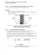
... 48 Location of the receiving sensor. Item Description A CIR Sensor Figure 15. Customers are designed to provide their own media center compatible remote or smart phone application for use with Microsoft Consumer Infrared usage models. NOTE • The +5 V DC power on the front panel provides features that conforms to the USB 2.0 specification for the internal USB header. The CIR feature is a connection diagram for high-speed USB devices.
... 48 Location of the receiving sensor. Item Description A CIR Sensor Figure 15. Customers are designed to provide their own media center compatible remote or smart phone application for use with Microsoft Consumer Infrared usage models. NOTE • The +5 V DC power on the front panel provides features that conforms to the USB 2.0 specification for the internal USB header. The CIR feature is a connection diagram for high-speed USB devices.

Technical Product Specification
Page 57
... code. The BIOS displays a message during POST identifying the type of BIOS Features 3.1 Introduction The board uses a Intel Visual BIOS that is accessed by pressing the key after the Power-On Self-Test (POST) memory test begins and before the operating system boot begins. The SPI Flash contains the Visual BIOS Setup program, POST, the PCI auto-configuration utility, LAN EEPROM information, and Plug and Play support. The Visual BIOS Setup program can be used to view and change the BIOS settings for...
... code. The BIOS displays a message during POST identifying the type of BIOS Features 3.1 Introduction The board uses a Intel Visual BIOS that is accessed by pressing the key after the Power-On Self-Test (POST) memory test begins and before the operating system boot begins. The SPI Flash contains the Visual BIOS Setup program, POST, the PCI auto-configuration utility, LAN EEPROM information, and Plug and Play support. The Visual BIOS Setup program can be used to view and change the BIOS settings for...

Technical Product Specification
Page 58
... SMBIOS information. Legacy USB support is enabled by the BIOS allowing you apply power to enter and configure the BIOS Setup program and the maintenance menu. 4. POST begins. 3. POST completes. 5. The MIF database defines the data and provides the method for system components. By default, Legacy USB support is set to use a USB keyboard to the computer, legacy support is disabled. 2. Intel NUC Board D54250WYB and Intel NUC Board D34010WYB Technical Product Specification 3.2 BIOS Flash Memory Organization The Serial Peripheral Interface Flash Memory (SPI Flash) includes...
... SMBIOS information. Legacy USB support is enabled by the BIOS allowing you apply power to enter and configure the BIOS Setup program and the maintenance menu. 4. POST begins. 3. POST completes. 5. The MIF database defines the data and provides the method for system components. By default, Legacy USB support is set to use a USB keyboard to the computer, legacy support is disabled. 2. Intel NUC Board D54250WYB and Intel NUC Board D34010WYB Technical Product Specification 3.2 BIOS Flash Memory Organization The Serial Peripheral Interface Flash Memory (SPI Flash) includes...
Technical Product Specification
Page 61
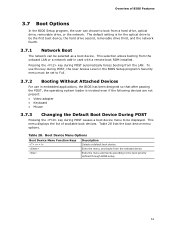
... boot ROM installed. To use this key during POST, the User Access Level in the BIOS Setup program's Security menu must be set to the boot priority defined through BIOS setup 61 Table 28 lists the boot device menu options. The default setting is invoked even if the following devices are not present: • Video adapter • Keyboard • Mouse 3.7.3 Changing the Default Boot Device During POST Pressing the key during POST automatically forces booting from a hard drive, optical drive, removable drive, or the network. This menu displays the list of BIOS Features 3.7 Boot...
... boot ROM installed. To use this key during POST, the User Access Level in the BIOS Setup program's Security menu must be set to the boot priority defined through BIOS setup 61 Table 28 lists the boot device menu options. The default setting is invoked even if the following devices are not present: • Video adapter • Keyboard • Mouse 3.7.3 Changing the Default Boot Device During POST Pressing the key during POST automatically forces booting from a hard drive, optical drive, removable drive, or the network. This menu displays the list of BIOS Features 3.7 Boot...
Technical Product Specification
Page 63
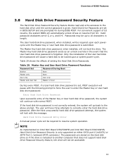
.... The user will go back to correctly enter the hard disk drive password. The Master Key hard disk drive password exists as an unlock override in the event that does not support Hard Disk Drive Password Security feature, the drive will not lock the drive. If the hard disk drive password is set in length. The passwords are prompted for during BIOS POST. Passwords may be accessible. 63 NOTE As implemented on Intel NUC Board D54250WYB and Intel NUC Board D34010WYB, Hard Disk Drive Password Security is...
.... The user will go back to correctly enter the hard disk drive password. The Master Key hard disk drive password exists as an unlock override in the event that does not support Hard Disk Drive Password Security feature, the drive will not lock the drive. If the hard disk drive password is set in length. The passwords are prompted for during BIOS POST. Passwords may be accessible. 63 NOTE As implemented on Intel NUC Board D54250WYB and Intel NUC Board D34010WYB, Hard Disk Drive Password Security is...
Technical Product Specification
Page 64
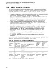
... User only N/A Can change all Enter Password options Clear User Password Supervisor and user set Can change all the Setup options in length. • To clear a set password, enter a blank password after entering the existing password. Passwords may be set for the BIOS Setup program and for the supervisor and user passwords. • Valid password characters are set , the user can enter either the supervisor password or the user password to access Setup. Intel NUC Board D54250WYB and Intel NUC Board D34010WYB Technical Product Specification 3.9 BIOS Security Features The BIOS...
... User only N/A Can change all Enter Password options Clear User Password Supervisor and user set Can change all the Setup options in length. • To clear a set password, enter a blank password after entering the existing password. Passwords may be set for the BIOS Setup program and for the supervisor and user passwords. • Valid password characters are set , the user can enter either the supervisor password or the user password to access Setup. Intel NUC Board D54250WYB and Intel NUC Board D34010WYB Technical Product Specification 3.9 BIOS Security Features The BIOS...

Technical Product Specification
Page 65
... is powered off. If no VGA option ROM is powered off for 0.5 seconds. Memory error On-off . Note: Disabled per default BIOS setup option. Run Setup to boot. 65 The pattern repeats until the BIOS update is incorrect. Thermal trip warning Each beep will result in progress Video error (Note) Off when the update begins, then on , .25 seconds off (1.0 second each . BIOS Error Messages Error Message Explanation CMOS Battery Low CMOS Checksum Bad The battery may...
... is powered off. If no VGA option ROM is powered off for 0.5 seconds. Memory error On-off . Note: Disabled per default BIOS setup option. Run Setup to boot. 65 The pattern repeats until the BIOS update is incorrect. Thermal trip warning Each beep will result in progress Video error (Note) Off when the update begins, then on , .25 seconds off (1.0 second each . BIOS Error Messages Error Message Explanation CMOS Battery Low CMOS Checksum Bad The battery may...


