
Product Guide
Page 3
... BIOS error messages and beep codes B Regulatory Compliance: safety and EMC regulations, product certification Conventions The following conventions are used in this manual: CAUTION Cautions warn the user about how to prevent damage to hardware or loss of product features 2 Installing and Replacing Desktop Board Components: instructions on how to important information. may not be supported without further evaluation by Intel. Preface This Product Guide...
... BIOS error messages and beep codes B Regulatory Compliance: safety and EMC regulations, product certification Conventions The following conventions are used in this manual: CAUTION Cautions warn the user about how to prevent damage to hardware or loss of product features 2 Installing and Replacing Desktop Board Components: instructions on how to important information. may not be supported without further evaluation by Intel. Preface This Product Guide...
Product Guide
Page 5
... Chipset 14 Graphics Subsystem ...14 Audio Subsystem ...14 Input/Output (I/O) Controller 15 LAN Subsystem ...15 LAN Subsystem Software 15 RJ-45 LAN Connector LEDs 16 Hi-Speed USB 2.0 Support 16 Enhanced IDE Interface ...17 Serial ATA...17 Expandability...17 BIOS ...17 Serial ATA and IDE Auto Configuration 17 PCI and PCI Express* Auto Configuration 17 Security Passwords ...18 Chassis Intrusion...18 Power Management Features 18 ACPI...18 Power Connectors...18 Fan Connectors...19 Suspend to RAM (Instantly Available PC Technology 19 Wake from USB...20 Wake from PS/2 Keyboard...
... Chipset 14 Graphics Subsystem ...14 Audio Subsystem ...14 Input/Output (I/O) Controller 15 LAN Subsystem ...15 LAN Subsystem Software 15 RJ-45 LAN Connector LEDs 16 Hi-Speed USB 2.0 Support 16 Enhanced IDE Interface ...17 Serial ATA...17 Expandability...17 BIOS ...17 Serial ATA and IDE Auto Configuration 17 PCI and PCI Express* Auto Configuration 17 Security Passwords ...18 Chassis Intrusion...18 Power Management Features 18 ACPI...18 Power Connectors...18 Fan Connectors...19 Suspend to RAM (Instantly Available PC Technology 19 Wake from USB...20 Wake from PS/2 Keyboard...
Product Guide
Page 6
... the PCI Express x16 Card 35 Connecting the IDE Cable 36 Connecting the Serial ATA (SATA) Cable 37 Connecting Internal Headers 38 Installing a Front Panel Audio Solution 39 Connecting Hi-Speed USB 2.0 Headers 40 Connecting the Front Panel Header 40 Setting Up the Flexible 6-Channel Audio with Jack Re-tasking (Optional 41 Connecting Chassis Fan Cables 42 Connecting Power Cables 43 Other Connectors...44 Setting the BIOS Configuration Jumper 45 Clearing Passwords ...46 Replacing the Battery ...47 3 Updating the BIOS Updating the BIOS with the Intel® Express BIOS Update Utility 53...
... the PCI Express x16 Card 35 Connecting the IDE Cable 36 Connecting the Serial ATA (SATA) Cable 37 Connecting Internal Headers 38 Installing a Front Panel Audio Solution 39 Connecting Hi-Speed USB 2.0 Headers 40 Connecting the Front Panel Header 40 Setting Up the Flexible 6-Channel Audio with Jack Re-tasking (Optional 41 Connecting Chassis Fan Cables 42 Connecting Power Cables 43 Other Connectors...44 Setting the BIOS Configuration Jumper 45 Clearing Passwords ...46 Replacing the Battery ...47 3 Updating the BIOS Updating the BIOS with the Intel® Express BIOS Update Utility 53...
Product Guide
Page 7
... ...9 2. Power Supply Requirements 13 4. Hi-Speed USB 2.0 Header Signal Names 40 8. AC '97 Audio Header Signal Names 39 7. EMC Regulations...62 15. Installing a PCI Express x16 Card 34 16. Desktop Boards D102GGC2 Components 12 3. Beep Codes...55 11. Location of the Chassis Fan Headers 42 22. Connecting the Serial ATA Cable 37 19. Internal Headers ...38 20. Lead-Free Board Markings 61 14. Intel Desktop Board D102GGC2 Components 11 2. Remove the Processor from the Protective Processor Cover/Do Not Touch 28 10. Back Panel Audio Connectors for High...
... ...9 2. Power Supply Requirements 13 4. Hi-Speed USB 2.0 Header Signal Names 40 8. AC '97 Audio Header Signal Names 39 7. EMC Regulations...62 15. Installing a PCI Express x16 Card 34 16. Desktop Boards D102GGC2 Components 12 3. Beep Codes...55 11. Location of the Chassis Fan Headers 42 22. Connecting the Serial ATA Cable 37 19. Internal Headers ...38 20. Lead-Free Board Markings 61 14. Intel Desktop Board D102GGC2 Components 11 2. Remove the Processor from the Protective Processor Cover/Do Not Touch 28 10. Back Panel Audio Connectors for High...
Product Guide
Page 9
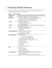
... two USB headers • Four Serial ATA (SATA) channels (1.5 Gb/s) • Two IDE interfaces with ATA-100 support (four devices) BIOS • One VGA connector • One diskette drive interface • One parallel port • One serial port • PS/2* keyboard and mouse ports • Intel® BIOS • Support for SMBIOS • Intel® Rapid BIOS Boot • Intel® Express BIOS Update Power Management • Support for Advanced Configuration and Power Interface (ACPI) • Suspend to RAM (STR) • Wake on USB, PCI, PCI Express, PS/2, LAN...
... two USB headers • Four Serial ATA (SATA) channels (1.5 Gb/s) • Two IDE interfaces with ATA-100 support (four devices) BIOS • One VGA connector • One diskette drive interface • One parallel port • One serial port • PS/2* keyboard and mouse ports • Intel® BIOS • Support for SMBIOS • Intel® Rapid BIOS Boot • Intel® Express BIOS Update Power Management • Support for Advanced Configuration and Power Interface (ACPI) • Suspend to RAM (STR) • Wake on USB, PCI, PCI Express, PS/2, LAN...
Product Guide
Page 12
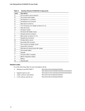
... V W Desktop Boards D102GGC2 Components Description PCI bus add-in card connectors Front panel audio header PCI Express* x1 connector PCI Express x16 connector Back panel connectors 12 V processor core voltage connector (2 x 2) Rear fan (3-pin) Processor socket Processor fan header (4-pin) Chassis intrusion connector Main power connector (2 x 12) Diskette drive connector Primary IDE connector Secondary IDE connector Front chassis fan header (3-pin) Serial ATA connectors Alternate front panel power LED header Front panel header Speaker Hi-speed USB 2.0 headers BIOS configuration jumper Battery...
... V W Desktop Boards D102GGC2 Components Description PCI bus add-in card connectors Front panel audio header PCI Express* x1 connector PCI Express x16 connector Back panel connectors 12 V processor core voltage connector (2 x 2) Rear fan (3-pin) Processor socket Processor fan header (4-pin) Chassis intrusion connector Main power connector (2 x 12) Diskette drive connector Primary IDE connector Secondary IDE connector Front chassis fan header (3-pin) Serial ATA connectors Alternate front panel power LED header Front panel header Speaker Hi-speed USB 2.0 headers BIOS configuration jumper Battery...
Product Guide
Page 13
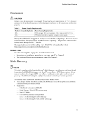
The supported processors list for desktop board D102GGC2 is located on installing or upgrading the processor, page 27 in damage to this effect on the screen at : http://support.intel.com/support/motherboards/desktop/ Related Links: Go to configure the memory controller for more information about: • Instructions on the web at power up. The BIOS will see a notification to the board, or the system may result in Chapter 2 • The location of 13 A continuous...
The supported processors list for desktop board D102GGC2 is located on installing or upgrading the processor, page 27 in damage to this effect on the screen at : http://support.intel.com/support/motherboards/desktop/ Related Links: Go to configure the memory controller for more information about: • Instructions on the web at power up. The BIOS will see a notification to the board, or the system may result in Chapter 2 • The location of 13 A continuous...
Product Guide
Page 15
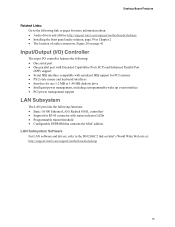
... about: • Audio drivers and utilities http://support.intel.com/support/motherboards/desktop/ • Installing the front panel audio solution, page 39 in Chapter 2 • The location of audio connectors, Figure 20 on page 41 Input/Output (I/O) Controller The super I/O controller features the following: • One serial port • One parallel port with Extended Capabilities Port (ECP) and Enhanced Parallel Port (EPP) support • Serial IRQ interface compatible with serialized IRQ support for PCI systems • PS...
... about: • Audio drivers and utilities http://support.intel.com/support/motherboards/desktop/ • Installing the front panel audio solution, page 39 in Chapter 2 • The location of audio connectors, Figure 20 on page 41 Input/Output (I/O) Controller The super I/O controller features the following: • One serial port • One parallel port with Extended Capabilities Port (ECP) and Enhanced Parallel Port (EPP) support • Serial IRQ interface compatible with serialized IRQ support for PCI systems • PS...
Product Guide
Page 16
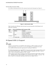
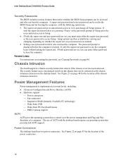
Intel Desktop Board D102GGC2 Product Guide RJ-45 LAN Connector LEDs Two LEDs are backward compatible with USB 1.1 devices. four ports routed to the back panel and four routed to USB 1.1 operation. Use a shielded cable that fully support USB 2.0 transfer rates. USB 1.1 devices will function normally at USB 1.1 speeds. Disabling Hi-Speed USB in the BIOS reverts all USB 2.0 ports to two internal USB 2.0 headers. LAN Connector LEDs OM18208 Table 4 describes the LED states when the board is powered up to a USB port might not meet FCC Class B requirements, even if...
Intel Desktop Board D102GGC2 Product Guide RJ-45 LAN Connector LEDs Two LEDs are backward compatible with USB 1.1 devices. four ports routed to the back panel and four routed to USB 1.1 operation. Use a shielded cable that fully support USB 2.0 transfer rates. USB 1.1 devices will function normally at USB 1.1 speeds. Disabling Hi-Speed USB in the BIOS reverts all USB 2.0 ports to two internal USB 2.0 headers. LAN Connector LEDs OM18208 Table 4 describes the LED states when the board is powered up to a USB port might not meet FCC Class B requirements, even if...

Product Guide
Page 17
.../100 modes Serial ATA The desktop board supports four Serial ATA channels (1.5 Gb/s), connecting one device per channel. PCI and PCI Express* Auto Configuration If you install a PCI or PCI Express add-in the BIOS automatically detects and configures the resources (IRQs, DMA channels, and I/O space) for your computer. You do not need to four IDE devices (such as hard drives) • ATAPI-style devices (such as a hard drive) in your computer, the PCI/PCI Express autoconfiguration utility in card. 17 The interface supports: •...
.../100 modes Serial ATA The desktop board supports four Serial ATA channels (1.5 Gb/s), connecting one device per channel. PCI and PCI Express* Auto Configuration If you install a PCI or PCI Express add-in the BIOS automatically detects and configures the resources (IRQs, DMA channels, and I/O space) for your computer. You do not need to four IDE devices (such as hard drives) • ATAPI-style devices (such as a hard drive) in your computer, the PCI/PCI Express autoconfiguration utility in card. 17 The interface supports: •...
Product Guide
Page 18
... technology) ⎯ Wake from USB ⎯ Wake from PS/2 keyboard/mouse ⎯ PME# wakeup support ACPI ACPI gives the operating system direct control over the power management and Plug and Play functions of ACPI with the following restrictions: • The supervisor password gives unrestricted access to view and change all Setup options. If both the supervisor and user passwords are set , the computer boots without asking for a password. The use of a computer. Power Connectors The desktop board...
... technology) ⎯ Wake from USB ⎯ Wake from PS/2 keyboard/mouse ⎯ PME# wakeup support ACPI ACPI gives the operating system direct control over the power management and Plug and Play functions of ACPI with the following restrictions: • The supervisor password gives unrestricted access to view and change all Setup options. If both the supervisor and user passwords are set , the computer boots without asking for a password. The use of a computer. Power Connectors The desktop board...

Product Guide
Page 19
... using this desktop board must be off. Failure to RAM (Instantly Available PC Technology) CAUTIONS For Instantly Available PC technology, the 5 V standby line for the location of delivering adequate +5 V standby current. Desktop Board Features Fan Connectors The desktop board has a 4-pin processor fan header and two 3-pin chassis fan headers. Instantly Available PC technology enables the board to enter the ACPI S3 (Suspend-to support multiple wake events from the PCI and/or USB buses exceeds power supply capacity, the desktop board may lose register settings...
... using this desktop board must be off. Failure to RAM (Instantly Available PC Technology) CAUTIONS For Instantly Available PC technology, the 5 V standby line for the location of delivering adequate +5 V standby current. Desktop Board Features Fan Connectors The desktop board has a 4-pin processor fan header and two 3-pin chassis fan headers. Instantly Available PC technology enables the board to enter the ACPI S3 (Suspend-to support multiple wake events from the PCI and/or USB buses exceeds power supply capacity, the desktop board may lose register settings...
Product Guide
Page 20
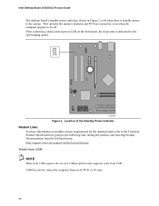
... Specification by the LED turning amber. CR1 OM19149 Figure 3. Location of a USB peripheral that supports wake from an ACPI S1 or S3 state. 20 USB bus activity wakes the computer from USB. This includes the memory modules and PCI bus connectors, even when the computer appears to the following link, finding the product, and selecting Product Documentation from the left-hand menu: http://support.intel.com/support/motherboards/desktop/ Wake from USB NOTE Wake from USB...
... Specification by the LED turning amber. CR1 OM19149 Figure 3. Location of a USB peripheral that supports wake from an ACPI S1 or S3 state. 20 USB bus activity wakes the computer from USB. This includes the memory modules and PCI bus connectors, even when the computer appears to the following link, finding the product, and selecting Product Documentation from the left-hand menu: http://support.intel.com/support/motherboards/desktop/ Wake from USB NOTE Wake from USB...

Product Guide
Page 23
... in personal injury or equipment damage. 2 Installing and Replacing Desktop Board Components This chapter tells you how to: • Install the I/O shield • Install and remove the desktop board • Install and remove a processor and memory • Install and remove a PCI Express x16 card • Connect the IDE and Serial ATA cables • Connect internal headers • Set up a log to record information about your computer, such as model, serial numbers, installed options, and configuration information. • Electrostatic discharge (ESD) can...
... in personal injury or equipment damage. 2 Installing and Replacing Desktop Board Components This chapter tells you how to: • Install the I/O shield • Install and remove the desktop board • Install and remove a processor and memory • Install and remove a PCI Express x16 card • Connect the IDE and Serial ATA cables • Connect internal headers • Set up a log to record information about your computer, such as model, serial numbers, installed options, and configuration information. • Electrostatic discharge (ESD) can...

Product Guide
Page 32
... 23. 2. Remove the PCI Express video card if it was removed prior to installing the DIMMs. 11. Remove the computer's cover and locate the DIMM sockets (see Figure 14). 8. Holding the DIMM by the edges, remove it from being easily opened and closed. 5. Turn off the computer and disconnect the AC power cord. 3. Position the DIMM above the socket. Turn off all peripheral devices connected to the...
... 23. 2. Remove the PCI Express video card if it was removed prior to installing the DIMMs. 11. Remove the computer's cover and locate the DIMM sockets (see Figure 14). 8. Holding the DIMM by the edges, remove it from being easily opened and closed. 5. Turn off the computer and disconnect the AC power cord. 3. Position the DIMM above the socket. Turn off all peripheral devices connected to the...

Product Guide
Page 39
.... 2. Remove the cover. 4. Observe the precautions in "Before You Begin" on page 23. 2. Installing and Replacing Desktop Board Components Installing a Front Panel Audio Solution Figure 19, D on the AC '97 audio specification. Install a correctly keyed and shielded front panel audio cable. Connect the audio cable to the computer. NOTE: some chassis still use a front panel audio solution based on page 38 shows the location of the yellow front panel audio header. Replace the cover. The front panel audio jacks...
.... 2. Remove the cover. 4. Observe the precautions in "Before You Begin" on page 23. 2. Installing and Replacing Desktop Board Components Installing a Front Panel Audio Solution Figure 19, D on the AC '97 audio specification. Install a correctly keyed and shielded front panel audio cable. Connect the audio cable to the computer. NOTE: some chassis still use a front panel audio solution based on page 38 shows the location of the yellow front panel audio header. Replace the cover. The front panel audio jacks...

Product Guide
Page 45
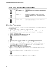
... jumper settings for the Setup program modes. 45 Figure 24 shows the location of the BIOS Configuration Jumper Block The three-pin BIOS jumper block enables all board configuration to be done in unreliable computer operation. Moving the jumper with the power on may result in the BIOS Setup program. Installing and Replacing Desktop Board Components Setting the BIOS Configuration Jumper NOTE Always turn off the power and unplug the power cord from the computer before changing the jumper. Location of the desktop board's BIOS configuration jumper...
... jumper settings for the Setup program modes. 45 Figure 24 shows the location of the BIOS Configuration Jumper Block The three-pin BIOS jumper block enables all board configuration to be done in unreliable computer operation. Moving the jumper with the power on may result in the BIOS Setup program. Installing and Replacing Desktop Board Components Setting the BIOS Configuration Jumper NOTE Always turn off the power and unplug the power cord from the computer before changing the jumper. Location of the desktop board's BIOS configuration jumper...
Product Guide
Page 46
Intel Desktop Board D102GGC2 Product Guide Table 9. Use this menu to boot. 7. Find the configuration jumper block (see Figure 24). 5. Place the jumper on pins 1-2 as shown below . 1 3 13. Press and Setup displays a pop-up screen requesting that the board is installed in "Before You Begin" on page 23. 2. To restore normal operation, place the jumper on pins 2-3 as shown below . 1 3 6. Replace the cover, plug in the computer, turn on the computer, and...
Intel Desktop Board D102GGC2 Product Guide Table 9. Use this menu to boot. 7. Find the configuration jumper block (see Figure 24). 5. Place the jumper on pins 1-2 as shown below . 1 3 13. Press and Setup displays a pop-up screen requesting that the board is installed in "Before You Begin" on page 23. 2. To restore normal operation, place the jumper on pins 2-3 as shown below . 1 3 6. Replace the cover, plug in the computer, turn on the computer, and...
Product Guide
Page 53
....) 4. Download the file to your hard drive where it was saved. This is included in a USB floppy disk drive or other applications. Updating the BIOS with the Iflash Memory Update Utility With the Iflash BIOS update utility you can access the BIOS Setup program by pressing the key after the Power-On Self-Test (POST) memory test begins and before the operating system boot begins. The BIOS update file contains: • New BIOS files • BIOS recovery files • Intel Flash Memory Update Utility 53 You can update...
....) 4. Download the file to your hard drive where it was saved. This is included in a USB floppy disk drive or other applications. Updating the BIOS with the Iflash Memory Update Utility With the Iflash BIOS update utility you can access the BIOS Setup program by pressing the key after the Power-On Self-Test (POST) memory test begins and before the operating system boot begins. The BIOS update file contains: • New BIOS files • BIOS recovery files • Intel Flash Memory Update Utility 53 You can update...
Product Guide
Page 54
... the update files updates the BIOS. Intel Desktop Board D102GGC2 Product Guide You can obtain the BIOS update file through your computer supplier or by navigating to the Desktop Board D102GGC2 page on the Intel World Wide Web site at: http://support.intel.com/support/motherboards/desktop Navigate to : http://support.intel.com/support/motherboards/desktop/ 54 The Iflash Memory Update utility allows you to remove the diskette and to view the POST messages. As the computer boots, check the BIOS identifier (version number...
... the update files updates the BIOS. Intel Desktop Board D102GGC2 Product Guide You can obtain the BIOS update file through your computer supplier or by navigating to the Desktop Board D102GGC2 page on the Intel World Wide Web site at: http://support.intel.com/support/motherboards/desktop Navigate to : http://support.intel.com/support/motherboards/desktop/ 54 The Iflash Memory Update utility allows you to remove the diskette and to view the POST messages. As the computer boots, check the BIOS identifier (version number...


