
Product Guide
Page 7
... Panel Audio Header Signal Names for a Flexible 6-Channel Audio System 41 21. Lift the Load Plate and Don't Touch the Socket Contacts 27 8. Location of Other Connectors on Desktop Board D102GGC2 44 24. Jumper Settings for the BIOS Setup Program Modes 46 10. Product Certification Markings 63 vii...Location of the Chassis Fan Headers 42 22. Use DDR DIMMs ...31 14. Connecting the Serial ATA Cable 37 19. Desktop Boards D102GGC2 Components 12 3. BIOS Error Messages 55 12. Close the Load Plate ...29 12. Contents Figures 1. Intel Desktop Board D102GGC2 Components 11 2.
... Panel Audio Header Signal Names for a Flexible 6-Channel Audio System 41 21. Lift the Load Plate and Don't Touch the Socket Contacts 27 8. Location of Other Connectors on Desktop Board D102GGC2 44 24. Jumper Settings for the BIOS Setup Program Modes 46 10. Product Certification Markings 63 vii...Location of the Chassis Fan Headers 42 22. Use DDR DIMMs ...31 14. Connecting the Serial ATA Cable 37 19. Desktop Boards D102GGC2 Components 12 3. BIOS Error Messages 55 12. Close the Load Plate ...29 12. Contents Figures 1. Intel Desktop Board D102GGC2 Components 11 2.
Product Guide
Page 13
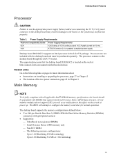
...the LGA775 package. The supported processors list for 10 ms ATX12V (version 2.0 or greater) compliant power supply Desktop board D102GGC2 supports an Intel processor in damage to the board, or the system may not function properly. Power Supply Requirements Platform Compatibility Guide 05A 04A...in Chapter 2 Main Memory NOTE To be fully compliant with gold-plated contacts • Support for normal operation. Table 3. The BIOS will see a notification to this effect on the screen at : http://support.intel.com/support/motherboards/desktop/ Related Links: Go to the following memory...
...the LGA775 package. The supported processors list for 10 ms ATX12V (version 2.0 or greater) compliant power supply Desktop board D102GGC2 supports an Intel processor in damage to the board, or the system may not function properly. Power Supply Requirements Platform Compatibility Guide 05A 04A...in Chapter 2 Main Memory NOTE To be fully compliant with gold-plated contacts • Support for normal operation. Table 3. The BIOS will see a notification to this effect on the screen at : http://support.intel.com/support/motherboards/desktop/ Related Links: Go to the following memory...
Product Guide
Page 27
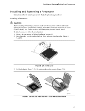
...standby power LED should not be lit (see Figure 3 on page 23. 2. To install a processor, follow these instructions: 1. Lift the Load Plate and Don't Touch the Socket Contacts 27 Observe the precautions in "Before You Begin" on page 20). A B OM17210 Figure 6. Failure to the... C D D OM17211 Figure 7. Open the socket lever by unplugging the power cord from the socket (Figure 6, A and B). Lift the load plate (Figure 7, C). Installing and Replacing Desktop Board Components Installing and Removing a Processor Instructions on how to install a processor to do so could damage ...
...standby power LED should not be lit (see Figure 3 on page 23. 2. To install a processor, follow these instructions: 1. Lift the Load Plate and Don't Touch the Socket Contacts 27 Observe the precautions in "Before You Begin" on page 20). A B OM17210 Figure 6. Failure to the... C D D OM17211 Figure 7. Open the socket lever by unplugging the power cord from the socket (Figure 6, A and B). Lift the load plate (Figure 7, C). Installing and Replacing Desktop Board Components Installing and Removing a Processor Instructions on how to install a processor to do so could damage ...

Product Guide
Page 28
... at the edges, being careful not to the package if the processor is removed from the socket. OM17213 Figure 9. Remove the Processor from the load plate (Figure 8, E). Always replace the processor back to touch the bottom of the processor (see Figure 9). E OM17228 Figure 8. Remove the Protective Socket Cover 5. Do not discard... cover from the Protective Processor Cover/Do Not Touch 28 Always replace the socket cover if the processor is removed from the protective processor cover. Intel Desktop Board D102GGC2 Product Guide 4. Remove the processor from the socket.
... at the edges, being careful not to the package if the processor is removed from the socket. OM17213 Figure 9. Remove the Processor from the load plate (Figure 8, E). Always replace the processor back to touch the bottom of the processor (see Figure 9). E OM17228 Figure 8. Remove the Protective Socket Cover 5. Do not discard... cover from the Protective Processor Cover/Do Not Touch 28 Always replace the socket cover if the processor is removed from the protective processor cover. Intel Desktop Board D102GGC2 Product Guide 4. Remove the processor from the socket.

Product Guide
Page 29
Lower the processor straight down on the load plate (Figure 11, I OM17215 Figure 11. Hold the processor with the socket (Figure 10, H). While pressing down without tilting or sliding the processor in Figure 10. G G H F H F Figure 10. Align notches (Figure 10, G) with your thumb and index fingers oriented as shown in the socket. J I ), close and engage the socket lever (Figure 11, J). Install Processor OM17214 7. Installing and Replacing Desktop Board Components 6. Make sure fingers align to the socket cutouts (Figure 10, F). Close the Load Plate 29
Lower the processor straight down on the load plate (Figure 11, I OM17215 Figure 11. Hold the processor with the socket (Figure 10, H). While pressing down without tilting or sliding the processor in Figure 10. G G H F H F Figure 10. Align notches (Figure 10, G) with your thumb and index fingers oriented as shown in the socket. J I ), close and engage the socket lever (Figure 11, J). Install Processor OM17214 7. Installing and Replacing Desktop Board Components 6. Make sure fingers align to the socket cutouts (Figure 10, F). Close the Load Plate 29