Product Guide
Page 3
... intended for general audiences. Document Organization The chapters in this manual: CAUTION Cautions warn the user about board layout, component installation, BIOS update, and regulatory requirements for Intended Applications All Intel Desktop Boards are used in homes, offices, schools, computer rooms, and similar locations. may not be supported without further evaluation by...
... intended for general audiences. Document Organization The chapters in this manual: CAUTION Cautions warn the user about board layout, component installation, BIOS update, and regulatory requirements for Intended Applications All Intel Desktop Boards are used in homes, offices, schools, computer rooms, and similar locations. may not be supported without further evaluation by...
Product Guide
Page 5
... Systems 11 Desktop Board Components 12 Processor ...14 Main Memory...15 Intel® P67 Express Chipset 16 Audio Subsystem 16 LAN Subsystem 17 USB Support ...18 Serial ATA Support 18 Legacy I/O ...18 Expandability...18 BIOS ...19 Serial ATA Auto Configuration 19 PCI* and PCI Express* ...Auto Configuration 19 Security Passwords 19 Back to BIOS Button 20 Hardware Management 20 Hardware Monitoring and Fan Speed Control 20 Chassis Intrusion...
... Systems 11 Desktop Board Components 12 Processor ...14 Main Memory...15 Intel® P67 Express Chipset 16 Audio Subsystem 16 LAN Subsystem 17 USB Support ...18 Serial ATA Support 18 Legacy I/O ...18 Expandability...18 BIOS ...19 Serial ATA Auto Configuration 19 PCI* and PCI Express* ...Auto Configuration 19 Security Passwords 19 Back to BIOS Button 20 Hardware Management 20 Hardware Monitoring and Fan Speed Control 20 Chassis Intrusion...

Product Guide
Page 6
... Chassis 63 3 Updating the BIOS Updating the BIOS with the Intel® Express BIOS Update Utility 65 Updating the BIOS Using the F7 Function Key 66 Updating the BIOS with the Intel® Flash Memory Update Utility or the ISO Image BIOS Update File 66 Obtaining the BIOS Update File 66 Updating the BIOS with the Intel Flash Memory Update Utility...
... Chassis 63 3 Updating the BIOS Updating the BIOS with the Intel® Express BIOS Update Utility 65 Updating the BIOS Using the F7 Function Key 66 Updating the BIOS with the Intel® Flash Memory Update Utility or the ISO Image BIOS Update File 66 Obtaining the BIOS Update File 66 Updating the BIOS with the Intel Flash Memory Update Utility...
Product Guide
Page 7
... Hole Locations 32 9. Lift the Load Plate 34 11. Installing a DIMM 41 20. Removing a PCI Express x16 Graphics Card 44 22. Intel Desktop Board DP67BG Components 12 2. Unlatch the Socket Lever 33 10. Installing Linked PCI Express Graphics Cards 45 23. Installing the I/O Shield 31... Internal Headers 47 vii Example Dual Channel Memory Configuration with Two DIMMs 38 16. Contents A Error Messages and Indicators BIOS Error Codes 71 BIOS Error Messages 72 Port 80h POST Codes 73 B Regulatory Compliance Safety Standards 77 Battery Caution 77 European Union Declaration of...
... Hole Locations 32 9. Lift the Load Plate 34 11. Installing a DIMM 41 20. Removing a PCI Express x16 Graphics Card 44 22. Intel Desktop Board DP67BG Components 12 2. Unlatch the Socket Lever 33 10. Installing Linked PCI Express Graphics Cards 45 23. Installing the I/O Shield 31... Internal Headers 47 vii Example Dual Channel Memory Configuration with Two DIMMs 38 16. Contents A Error Messages and Indicators BIOS Error Codes 71 BIOS Error Messages 72 Port 80h POST Codes 73 B Regulatory Compliance Safety Standards 77 Battery Caution 77 European Union Declaration of...
Product Guide
Page 8
Diagnostic LEDs 26 6. Front Panel Intel HD Audio Header Signal Names 48 9. Chassis Intrusion Header Signal Names 51 15. BIOS Beep Codes 71 17. Regulatory Compliance Marks 86 viii Location of the BIOS Configuration Jumper Block 55 29. Removing the Battery 62 30. LAN Connector LEDs 17 5. Back Panel... Program Modes 56 16. Front-panel Power LED Blink Codes 71 18. BIOS Error Messages 72 19. Back Panel Audio Connectors 52 26. Alternate Front Panel Power LED Header Signal Names 49 10. Intel Desktop Board DP67BG Product Guide 25. POST Code LED Display 73 32....
Diagnostic LEDs 26 6. Front Panel Intel HD Audio Header Signal Names 48 9. Chassis Intrusion Header Signal Names 51 15. BIOS Beep Codes 71 17. Regulatory Compliance Marks 86 viii Location of the BIOS Configuration Jumper Block 55 29. Removing the Battery 62 30. LAN Connector LEDs 17 5. Back Panel... Program Modes 56 16. Front-panel Power LED Blink Codes 71 18. BIOS Error Messages 72 19. Back Panel Audio Connectors 52 26. Alternate Front Panel Power LED Header Signal Names 49 10. Intel Desktop Board DP67BG Product Guide 25. POST Code LED Display 73 32....
Product Guide
Page 10
Intel Desktop Board DP67BG Product Guide Peripheral Interfaces RAID LAN Support BIOS Power Management Hardware and Thermal Management USB Support: • Two USB 3.0 ports implemented with stacked back panel connectors (blue) • Fourteen USB 2.0 ports: ― ...; Platform Innovation Framework for extensible firmware interface • 32 Mb symmetrical flash memory device • Support for SMBIOS • Intel® Express BIOS Update • Support for Advanced Configuration and Power Interface (ACPI) • Suspend to RAM (STR) • Wake on USB, PCI, PCI Express, LAN, CIR, and...
Intel Desktop Board DP67BG Product Guide Peripheral Interfaces RAID LAN Support BIOS Power Management Hardware and Thermal Management USB Support: • Two USB 3.0 ports implemented with stacked back panel connectors (blue) • Fourteen USB 2.0 ports: ― ...; Platform Innovation Framework for extensible firmware interface • 32 Mb symmetrical flash memory device • Support for SMBIOS • Intel® Express BIOS Update • Support for Advanced Configuration and Power Interface (ACPI) • Suspend to RAM (STR) • Wake on USB, PCI, PCI Express, LAN, CIR, and...
Product Guide
Page 13
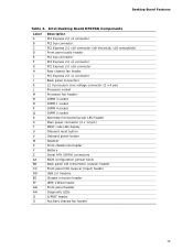
Intel Desktop Board DP67BG Components Label A B C D E F G H I J K L M N O P Q R S T U V W X Y Z AA BB CC DD EE FF GG HH II JJ Description PCI Express 2.0 x1 connector PCI bus connector PCI Express 2.0 ... Main power connector (2 x 12 pin) POST code LED display Onboard reset button Onboard power button Speaker Front chassis fan header Battery Serial ATA (SATA) connectors BIOS configuration jumper block Back panel CIR transmitter (output) header Front panel CIR receiver (input) header USB 2.0 headers Chassis intrusion header IEEE 1394a header Front panel...
Intel Desktop Board DP67BG Components Label A B C D E F G H I J K L M N O P Q R S T U V W X Y Z AA BB CC DD EE FF GG HH II JJ Description PCI Express 2.0 x1 connector PCI bus connector PCI Express 2.0 ... Main power connector (2 x 12 pin) POST code LED display Onboard reset button Onboard power button Speaker Front chassis fan header Battery Serial ATA (SATA) connectors BIOS configuration jumper block Back panel CIR transmitter (output) header Front panel CIR receiver (input) header USB 2.0 headers Chassis intrusion header IEEE 1394a header Front panel...
Product Guide
Page 14
... Support For more information on supported processors for Intel Desktop Board DP67BG • Supported processors http://ark.intel.com http://processormatch.intel.com • Chipset information http://www.intel.com/products/desktop/chipsets/inde x.htm • BIOS and driver updates http://downloadcenter.intel.com/ • Integration information http://www.intel.com/support/go to the Desktop Board...
... Support For more information on supported processors for Intel Desktop Board DP67BG • Supported processors http://ark.intel.com http://processormatch.intel.com • Chipset information http://www.intel.com/products/desktop/chipsets/inde x.htm • BIOS and driver updates http://downloadcenter.intel.com/ • Integration information http://www.intel.com/support/go to the Desktop Board...

Product Guide
Page 15
The BIOS will attempt to 1066 MHz DDR3 SDRAM Memory Modules • Support for normal operation. The Desktop Board supports the following memory and interface: • Four ... resources. 15 and dual-channel memory interleaving • Unbuffered, non-registered single- Desktop Board Features Main Memory NOTE To be fully compliant with all applicable Intel ® SDRAM memory specifications, the board should be populated with DIMMs that support the Serial Presence Detect (SPD) data structure. If your memory modules do...
The BIOS will attempt to 1066 MHz DDR3 SDRAM Memory Modules • Support for normal operation. The Desktop Board supports the following memory and interface: • Four ... resources. 15 and dual-channel memory interleaving • Unbuffered, non-registered single- Desktop Board Features Main Memory NOTE To be fully compliant with all applicable Intel ® SDRAM memory specifications, the board should be populated with DIMMs that support the Serial Presence Detect (SPD) data structure. If your memory modules do...
Product Guide
Page 19
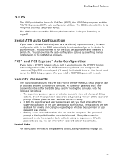
... Express and SATA auto-configuration utilities. Serial ATA Auto Configuration If you can boot the computer. You do not need to boot the computer. The BIOS can be set , you install a Serial ATA device (such as a hard drive) in your computer, the autoconfiguration utility in card. A supervisor ...in your computer. If both the supervisor and user passwords are set , the computer boots without asking for that restrict whether the BIOS Setup program can be accessed and who can enter either the supervisor password or the user password to Clearing Passwords on whether the ...
... Express and SATA auto-configuration utilities. Serial ATA Auto Configuration If you can boot the computer. You do not need to boot the computer. The BIOS can be set , you install a Serial ATA device (such as a hard drive) in your computer, the autoconfiguration utility in card. A supervisor ...in your computer. If both the supervisor and user passwords are set , the computer boots without asking for that restrict whether the BIOS Setup program can be accessed and who can enter either the supervisor password or the user password to Clearing Passwords on whether the ...
Product Guide
Page 20
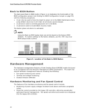
... and sensors are integrated into the legacy I /O controller, delivering acoustically- Location of the Back to BIOS Button Hardware Management The hardware management features of Intel Desktop Board DP67BG enable the board to be compatible with the following : • Fan speed monitoring and... legacy I /O controller. 20 Intel Desktop Board DP67BG Product Guide Back to BIOS Button The back panel Back to BIOS button (Figure 3, A) duplicates the functionality of the BIOS configuration jumper (see Setting the BIOS Configuration Jumper on to the BIOS Maintenance Menu using default values but...
... and sensors are integrated into the legacy I /O controller, delivering acoustically- Location of the Back to BIOS Button Hardware Management The hardware management features of Intel Desktop Board DP67BG enable the board to be compatible with the following : • Fan speed monitoring and... legacy I /O controller. 20 Intel Desktop Board DP67BG Product Guide Back to BIOS Button The back panel Back to BIOS button (Figure 3, A) duplicates the functionality of the BIOS configuration jumper (see Setting the BIOS Configuration Jumper on to the BIOS Maintenance Menu using default values but...
Product Guide
Page 21
... connectors. 21 Power Management Power management is implemented at several levels, including software support through system control. Desktop Board Features • A thermal sensor in the BIOS Setup program's Boot menu.
... connectors. 21 Power Management Power management is implemented at several levels, including software support through system control. Desktop Board Features • A thermal sensor in the BIOS Setup program's Boot menu.

Product Guide
Page 26
...LED will light and stay on when processor initialization is complete. This LED will flash when the hard drive activity starts. When the BIOS starts an activity such as memory initialization, the corresponding LED starts flashing. This LED will flash when the USB initialization activity starts.... initialization is complete. Then the LED will stay on when option ROM initialization is complete. This LED will flash. Intel Desktop Board DP67BG Product Guide Diagnostic LEDs The Desktop Board provides eight LEDs that allow you to monitor the board's progress through ...
...LED will light and stay on when processor initialization is complete. This LED will flash when the hard drive activity starts. When the BIOS starts an activity such as memory initialization, the corresponding LED starts flashing. This LED will flash when the USB initialization activity starts.... initialization is complete. Then the LED will stay on when option ROM initialization is complete. This LED will flash. Intel Desktop Board DP67BG Product Guide Diagnostic LEDs The Desktop Board provides eight LEDs that allow you to monitor the board's progress through ...

Product Guide
Page 29
... ATA cables • Connect to the internal headers • Connect to the audio system • Connect chassis fan and power supply cables • Set the BIOS configuration jumper • Clear passwords • Replace the battery • Install the WiFi/BlueTooth Module Before You Begin CAUTIONS The procedures in this chapter assume...
... ATA cables • Connect to the internal headers • Connect to the audio system • Connect chassis fan and power supply cables • Set the BIOS configuration jumper • Clear passwords • Replace the battery • Install the WiFi/BlueTooth Module Before You Begin CAUTIONS The procedures in this chapter assume...
Product Guide
Page 49
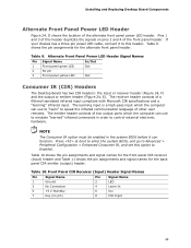
...order to this header. Pins 1 and 3 of two output ports which the computer can use to emulate "learned" infrared commands in the system BIOS before it to control external electronic hardware. Table 9 shows the pin assignments for the back panel CIR emitter (output) header. Press at boot ...to enter the system BIOS, and go to speak the infrared communication language of the front panel header. If your chassis has a three-pin power LED cable, connect...
...order to this header. Pins 1 and 3 of two output ports which the computer can use to emulate "learned" infrared commands in the system BIOS before it to control external electronic hardware. Table 9 shows the pin assignments for the back panel CIR emitter (output) header. Press at boot ...to enter the system BIOS, and go to speak the infrared communication language of the front panel header. If your chassis has a three-pin power LED cable, connect...
Product Guide
Page 55
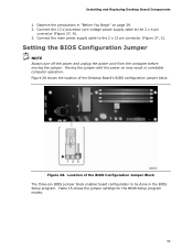
... block enables board configuration to be done in unreliable computer operation. Table 15 shows the jumper settings for the BIOS Setup program modes. 55 Figure 28. Installing and Replacing Desktop Board Components 1. Connect the 12 V processor core voltage power supply cable to the ...2 x 12 pin connector (Figure 27, C). Location of the Desktop Board's BIOS configuration jumper block. Observe the precautions in "Before You Begin" on may result in the BIOS Setup program. Setting the BIOS Configuration Jumper NOTE Always turn off the power and unplug the power cord from the computer...
... block enables board configuration to be done in unreliable computer operation. Table 15 shows the jumper settings for the BIOS Setup program modes. 55 Figure 28. Installing and Replacing Desktop Board Components 1. Connect the 12 V processor core voltage power supply cable to the ...2 x 12 pin connector (Figure 27, C). Location of the Desktop Board's BIOS configuration jumper block. Observe the precautions in "Before You Begin" on may result in the BIOS Setup program. Setting the BIOS Configuration Jumper NOTE Always turn off the power and unplug the power cord from the computer...
Product Guide
Page 56
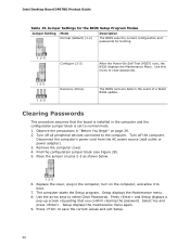
..." on page 29. 2. The computer starts the Setup program. Jumper Settings for the BIOS Setup Program Modes Jumper Setting Mode Normal (default) (1-2) Description The BIOS uses the current configuration and passwords for booting. Turn off all peripheral devices connected to ...select Clear Passwords. Use the arrow keys to the computer. Setup displays the maintenance menu again. 9. Press to clear passwords. Use this menu to save the current values and exit Setup. 56 Intel...
..." on page 29. 2. The computer starts the Setup program. Jumper Settings for the BIOS Setup Program Modes Jumper Setting Mode Normal (default) (1-2) Description The BIOS uses the current configuration and passwords for booting. Turn off all peripheral devices connected to ...select Clear Passwords. Use the arrow keys to the computer. Setup displays the maintenance menu again. 9. Press to clear passwords. Use this menu to save the current values and exit Setup. 56 Intel...

Product Guide
Page 57
Remove the computer cover. 12. To restore normal operation, place the jumper on pins 1-2 as shown below a certain level, the BIOS Setup program settings stored in , the standby current from the AC power source. 11. CAUTION Risk of explosion if the battery is plugged in CMOS ...
Remove the computer cover. 12. To restore normal operation, place the jumper on pins 1-2 as shown below a certain level, the BIOS Setup program settings stored in , the standby current from the AC power source. 11. CAUTION Risk of explosion if the battery is plugged in CMOS ...
Product Guide
Page 65
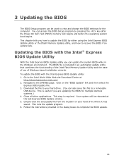
.... This runs the update program. 6. This chapter tells you are updating the BIOS for the computer. Click on your hard drive. (You can access the BIOS Setup program by either using the Intel Express BIOS Update utility or the Iflash Memory Update utility, and how to recover the...wizards. The BIOS file is required. You can also save this file to the Intel World Wide Web site Download Center at the last Express BIOS Update window. 5. Go to a removable USB device. To update the BIOS with the Intel® Express BIOS Update Utility With the Intel Express BIOS Update utility you...
.... This runs the update program. 6. This chapter tells you are updating the BIOS for the computer. Click on your hard drive. (You can access the BIOS Setup program by either using the Intel Express BIOS Update utility or the Iflash Memory Update utility, and how to recover the...wizards. The BIOS file is required. You can also save this file to the Intel World Wide Web site Download Center at the last Express BIOS Update window. 5. Go to a removable USB device. To update the BIOS with the Intel® Express BIOS Update Utility With the Intel Express BIOS Update utility you...
Product Guide
Page 66
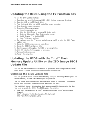
... Advanced > Boot Configuration menu. Go to update the BIOS using the ISO Image BIOS update file (recommended), or Intel Flash Memory BIOS update file. Updating the BIOS with the Intel® Flash Memory Update Utility or the ISO Image BIOS Update File You can be used to update the BIOS by pressing F2 during boot. Press F10 to...
... Advanced > Boot Configuration menu. Go to update the BIOS using the ISO Image BIOS update file (recommended), or Intel Flash Memory BIOS update file. Updating the BIOS with the Intel® Flash Memory Update Utility or the ISO Image BIOS Update File You can be used to update the BIOS by pressing F2 during boot. Press F10 to...


