
Product Guide
Page 3
...: instructions on how to install the Desktop Board and other environments, such as medical, industrial, alarm systems, test equipment, etc. Use Only for Intended Applications All Intel Desktop Boards are evaluated as Information Technology Equipment (I.T.E.) for use in homes, offices, schools, computer rooms, and similar locations. iii may not be supported without further evaluation by Intel. Preface This Product Guide gives information about board layout, component installation, BIOS update...
...: instructions on how to install the Desktop Board and other environments, such as medical, industrial, alarm systems, test equipment, etc. Use Only for Intended Applications All Intel Desktop Boards are evaluated as Information Technology Equipment (I.T.E.) for use in homes, offices, schools, computer rooms, and similar locations. iii may not be supported without further evaluation by Intel. Preface This Product Guide gives information about board layout, component installation, BIOS update...
Product Guide
Page 5
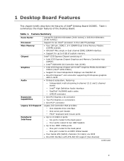
...13 Main Memory...13 Intel® G35 Express Chipset 14 Intel G35 Graphics Subsystem 14 Audio Subsystem 15 Legacy Input/Output (I/O) Controller 16 LAN Subsystem 16 LAN Status Indicators 16 Hi-Speed USB 2.0 Support 17 Enhanced IDE Interface 17 Serial ATA...17 Expandability...18 BIOS ...18 Serial ATA and IDE Auto Configuration 18 PCI and PCI Express* Auto Configuration 18 Security Passwords 18 Hardware Management Features 19 Hardware Monitoring and Fan Speed Control 19 Chassis Intrusion 19 Power Management Features 20 ACPI ...20 Hardware Support 20 Power Connectors 20 Fan Headers...
...13 Main Memory...13 Intel® G35 Express Chipset 14 Intel G35 Graphics Subsystem 14 Audio Subsystem 15 Legacy Input/Output (I/O) Controller 16 LAN Subsystem 16 LAN Status Indicators 16 Hi-Speed USB 2.0 Support 17 Enhanced IDE Interface 17 Serial ATA...17 Expandability...18 BIOS ...18 Serial ATA and IDE Auto Configuration 18 PCI and PCI Express* Auto Configuration 18 Security Passwords 18 Hardware Management Features 19 Hardware Monitoring and Fan Speed Control 19 Chassis Intrusion 19 Power Management Features 20 ACPI ...20 Hardware Support 20 Power Connectors 20 Fan Headers...

Product Guide
Page 6
... the IDE Cable 42 Connecting Serial ATA (SATA) Cables 43 Connecting to the Internal Headers and Connectors 44 S/PDIF Connector 45 Front Panel Audio Header 45 IEEE 1394a Header 46 Serial Port Header 46 Front Panel Header 46 Alternate Front Panel Power LED Header 47 USB 2.0 Headers 47 Chassis Intrusion Header 48 Connecting to the Onboard Audio System 48 Connecting Chassis Fan and Power Supply Cables 49 Chassis Fan Cables 49 Power Supply Cables 50 Setting the BIOS Configuration Jumper 51 Clearing Passwords 52 3 Updating the BIOS Updating the BIOS with the Intel® Express BIOS...
... the IDE Cable 42 Connecting Serial ATA (SATA) Cables 43 Connecting to the Internal Headers and Connectors 44 S/PDIF Connector 45 Front Panel Audio Header 45 IEEE 1394a Header 46 Serial Port Header 46 Front Panel Header 46 Alternate Front Panel Power LED Header 47 USB 2.0 Headers 47 Chassis Intrusion Header 48 Connecting to the Onboard Audio System 48 Connecting Chassis Fan and Power Supply Cables 49 Chassis Fan Cables 49 Power Supply Cables 50 Setting the BIOS Configuration Jumper 51 Clearing Passwords 52 3 Updating the BIOS Updating the BIOS with the Intel® Express BIOS...

Product Guide
Page 7
... 1. Location of the Chassis Fan Headers 49 26. Install the Processor 31 11. Dual Channel Memory Configuration with Three DIMMs 35 16. Connecting the IDE Cable 42 22. Connecting Power Supply Cables 50 27. Connecting the Diskette Drive Cable 41 21. Location of the +5 V Standby Power Indicator 22 4. Lift the Load Plate 30 8. Dual Channel Memory Configuration with Two DIMMs 34 14. Installing a DIMM 37 18. Installing a PCI Express x16 Card 39 19. Internal Headers 44 24. Installing the I/O Shield 27 5. Location of the BIOS Configuration Jumper Block...
... 1. Location of the Chassis Fan Headers 49 26. Install the Processor 31 11. Dual Channel Memory Configuration with Three DIMMs 35 16. Connecting the IDE Cable 42 22. Connecting Power Supply Cables 50 27. Connecting the Diskette Drive Cable 41 21. Location of the +5 V Standby Power Indicator 22 4. Lift the Load Plate 30 8. Dual Channel Memory Configuration with Two DIMMs 34 14. Installing a DIMM 37 18. Installing a PCI Express x16 Card 39 19. Internal Headers 44 24. Installing the I/O Shield 27 5. Location of the BIOS Configuration Jumper Block...
Product Guide
Page 9
... (SATA) channels (3.0 Gb/s) via VGA/DVI-D • One PCI Express* x16 connector supporting PCI Express graphics add-in cards • Onboard subsystem, featuring: ― Independent multi-streaming 6-channel (5.1) and 2-channel stereo ― Intel® High Definition Audio interface ― RealTek* ALC888S audio codec ― S/PDIF connector • One PCI Express x16 connector • Two PCI Express x1 connectors • One PCI* connector Legacy I/O Controller that provides: ― One diskette drive interface ― One serial port header ― PS/2* keyboard and mouse ports...
... (SATA) channels (3.0 Gb/s) via VGA/DVI-D • One PCI Express* x16 connector supporting PCI Express graphics add-in cards • Onboard subsystem, featuring: ― Independent multi-streaming 6-channel (5.1) and 2-channel stereo ― Intel® High Definition Audio interface ― RealTek* ALC888S audio codec ― S/PDIF connector • One PCI Express x16 connector • Two PCI Express x1 connectors • One PCI* connector Legacy I/O Controller that provides: ― One diskette drive interface ― One serial port header ― PS/2* keyboard and mouse ports...

Product Guide
Page 10
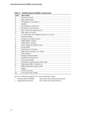
Intel Desktop Board DG35EC Product Guide Table 1. Feature Summary (continued) BIOS • Intel® Platform Innovation Framework for extensible firmware interface • 8 Mbit symmetrical flash memory device • Support for SMBIOS • Intel® Rapid BIOS Boot • Intel® Express BIOS Update Power Management • Support for Advanced Configuration and Power Interface (ACPI) • Suspend to RAM (STR) • Wake on USB, PCI Express, PS/2, LAN, and front panel • ENERGY STAR* capable Hardware Management • Voltage sense to detect out...
Intel Desktop Board DG35EC Product Guide Table 1. Feature Summary (continued) BIOS • Intel® Platform Innovation Framework for extensible firmware interface • 8 Mbit symmetrical flash memory device • Support for SMBIOS • Intel® Rapid BIOS Boot • Intel® Express BIOS Update Power Management • Support for Advanced Configuration and Power Interface (ACPI) • Suspend to RAM (STR) • Wake on USB, PCI Express, PS/2, LAN, and front panel • ENERGY STAR* capable Hardware Management • Voltage sense to detect out...
Product Guide
Page 12
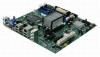
... PCI bus connector IEEE 1394a header PCI Express x1 connector 2 Speaker PCI Express x1 connector 1 PCI Express x16 connector Rear chassis fan header (3-pin) Back panel connectors 12 V processor core voltage connector (2 x 2 pin) Processor socket Processor fan header (4-pin) DDR2 DIMM 0 sockets DDR2 DIMM 1 sockets Front chassis fan header (3-pin) Serial header Diskette drive connector Main power connector (2 x 12 pin) IDE connector Chassis intrusion header Serial ATA connectors (4) Front panel header Alternate front panel power LED header High-speed USB 2.0 headers (2) BIOS configuration jumper...
... PCI bus connector IEEE 1394a header PCI Express x1 connector 2 Speaker PCI Express x1 connector 1 PCI Express x16 connector Rear chassis fan header (3-pin) Back panel connectors 12 V processor core voltage connector (2 x 2 pin) Processor socket Processor fan header (4-pin) DDR2 DIMM 0 sockets DDR2 DIMM 1 sockets Front chassis fan header (3-pin) Serial header Diskette drive connector Main power connector (2 x 12 pin) IDE connector Chassis intrusion header Serial ATA connectors (4) Front panel header Alternate front panel power LED header High-speed USB 2.0 headers (2) BIOS configuration jumper...

Product Guide
Page 15
...* 1.5 support ⎯ Shader Model 4.0 support • Enhanced video playback support, including: ⎯ Intel® Clear Video Technology (for more information go to http://www.intel.com/products/chipsets/clear_video/) ⎯ Support for playback of HD-DVD and Blu-ray Disc* technology DVDs ⎯ Software DVD at 30 fps full screen ⎯ Dynamic Video Memory Technology (DVMT) support up to 256 MB • Advanced display support, including: ⎯ DVI specification 1.0 compliant ⎯ Dual independent display support (VGA/DVI-D) ⎯ High Definition...
...* 1.5 support ⎯ Shader Model 4.0 support • Enhanced video playback support, including: ⎯ Intel® Clear Video Technology (for more information go to http://www.intel.com/products/chipsets/clear_video/) ⎯ Support for playback of HD-DVD and Blu-ray Disc* technology DVDs ⎯ Software DVD at 30 fps full screen ⎯ Dynamic Video Memory Technology (DVMT) support up to 256 MB • Advanced display support, including: ⎯ DVI specification 1.0 compliant ⎯ Dual independent display support (VGA/DVI-D) ⎯ High Definition...
Product Guide
Page 16
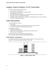
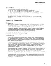
LAN Connector LEDs 16 These LEDs indicate the status of the LAN. Figure 2. Intel Desktop Board DG35EC Product Guide Legacy Input/Output (I/O) Controller The I/O controller features the following: • Low pin count (LPC) interface • One serial port interface via an onboard header • One diskette drive interface • Serial IRQ interface compatible with serialized IRQ support for PCI systems • PS/2-style mouse and keyboard interfaces • Intelligent power management, including a programmable wake up event interface...
LAN Connector LEDs 16 These LEDs indicate the status of the LAN. Figure 2. Intel Desktop Board DG35EC Product Guide Legacy Input/Output (I/O) Controller The I/O controller features the following: • Low pin count (LPC) interface • One serial port interface via an onboard header • One diskette drive interface • Serial IRQ interface compatible with serialized IRQ support for PCI systems • PS/2-style mouse and keyboard interfaces • Intelligent power management, including a programmable wake up event interface...
Product Guide
Page 17
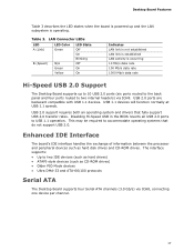
... The board's IDE interface handles the exchange of information between the processor and peripheral devices such as CD-ROM drives) • Older PIO Mode devices • Ultra DMA-33 and ATA-66/100 protocols Serial ATA The Desktop Board supports four Serial ATA channels (3.0 Gb/s) via ICH8. Table 3. USB 1.1 devices will function normally at USB 1.1 speeds. This may be required to two internal headers) via ICH8, connecting one device per channel. 17 LAN Connector LEDs LED A (Link) B (Speed) LED...
... The board's IDE interface handles the exchange of information between the processor and peripheral devices such as CD-ROM drives) • Older PIO Mode devices • Ultra DMA-33 and ATA-66/100 protocols Serial ATA The Desktop Board supports four Serial ATA channels (3.0 Gb/s) via ICH8. Table 3. USB 1.1 devices will function normally at USB 1.1 speeds. This may be required to two internal headers) via ICH8, connecting one device per channel. 17 LAN Connector LEDs LED A (Link) B (Speed) LED...

Product Guide
Page 18
... BIOS can be set , you install a Serial ATA or IDE device (such as a hard drive) in your computer. You do not need to view and change all Setup options. A supervisor password and a user password can be accessed and who can override the auto-configuration options by following expansion slots: • One PCI Express x16 connector • Two PCI Express x1 connectors • One PCI bus connector BIOS The BIOS provides the Power-On Self-Test (POST), the BIOS Setup program, the PCI/PCI Express and IDE auto-configuration utilities, and the video BIOS...
... BIOS can be set , you install a Serial ATA or IDE device (such as a hard drive) in your computer. You do not need to view and change all Setup options. A supervisor password and a user password can be accessed and who can override the auto-configuration options by following expansion slots: • One PCI Express x16 connector • Two PCI Express x1 connectors • One PCI bus connector BIOS The BIOS provides the Power-On Self-Test (POST), the BIOS Setup program, the PCI/PCI Express and IDE auto-configuration utilities, and the video BIOS...
Product Guide
Page 19
... fan speed or switch the fans off as needed Chassis Intrusion The board supports a chassis security feature that can be compatible with the Wired for a password. Hardware Management Features The hardware management features of Desktop Board DG35EC enable the board to be connected to the chassis intrusion header on the Desktop Board. The security feature uses a mechanical switch on page 52. If both passwords are set , the computer boots without asking for Management (WfM) specification. For instructions...
... fan speed or switch the fans off as needed Chassis Intrusion The board supports a chassis security feature that can be compatible with the Wired for a password. Hardware Management Features The hardware management features of Desktop Board DG35EC enable the board to be connected to the chassis intrusion header on the Desktop Board. The security feature uses a mechanical switch on page 52. If both passwords are set , the computer boots without asking for Management (WfM) specification. For instructions...
Product Guide
Page 20
...; WAKE# signal wake-up support • ENERGY STAR qualified ACPI ACPI gives the operating system direct control over the power management and Plug and Play functions of a computer. Hardware Support Power Connectors ATX12V-compliant power supplies can be set by using the Last Power State feature in before power was in the BIOS Setup program's Boot menu. Intel Desktop Board DG35EC Product Guide Power Management Features Power management is implemented at several levels, including: • Software support through system control.
...; WAKE# signal wake-up support • ENERGY STAR qualified ACPI ACPI gives the operating system direct control over the power management and Plug and Play functions of a computer. Hardware Support Power Connectors ATX12V-compliant power supplies can be set by using the Last Power State feature in before power was in the BIOS Setup program's Boot menu. Intel Desktop Board DG35EC Product Guide Power Management Features Power management is implemented at several levels, including: • Software support through system control.
Product Guide
Page 21
... PCI Bus Power Management Interface Specification. If the standby current necessary to provide adequate standby current when using this feature can damage the power supply. Instantly Available PC technology enables the board to support the standard Instantly Available (ACPI S3 sleep state) configuration. Failure to support multiple wake events from the PCI and/or USB buses exceeds power supply capacity, the Desktop Board may lose register settings stored in the ACPI S0 state. • The fans...
... PCI Bus Power Management Interface Specification. If the standby current necessary to provide adequate standby current when using this feature can damage the power supply. Instantly Available PC technology enables the board to support the standard Instantly Available (ACPI S3 sleep state) configuration. Failure to support multiple wake events from the PCI and/or USB buses exceeds power supply capacity, the Desktop Board may lose register settings stored in the ACPI S0 state. • The fans...
Product Guide
Page 25
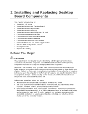
...though the front panel power button is not available, you how to: • Install the I/O shield • Install and remove the Desktop Board • Install and remove a processor • Install and remove memory • Install and remove a PCI Express x16 card • Connect the diskette drive cable • Connect the IDE and Serial ATA cables • Connect to the internal headers • Connect to the onboard audio system • Connect chassis fan and power supply cables • Set the BIOS configuration jumper • Clear passwords • Replace the battery Before You Begin...
...though the front panel power button is not available, you how to: • Install the I/O shield • Install and remove the Desktop Board • Install and remove a processor • Install and remove memory • Install and remove a PCI Express x16 card • Connect the diskette drive cable • Connect the IDE and Serial ATA cables • Connect to the internal headers • Connect to the onboard audio system • Connect chassis fan and power supply cables • Set the BIOS configuration jumper • Clear passwords • Replace the battery Before You Begin...
Product Guide
Page 33
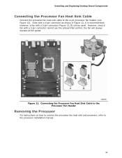
... the Processor For instructions on how to remove the processor fan heat sink and processor, refer to the 4-pin processor fan header (see Figure 12). However, since a fan with a 4-pin connector as shown in Figure 12, A is recommended; A fan with a 3-pin connector cannot use the onboard fan control, the fan will always operate at full speed. however, a fan with a 3-pin connector (Figure 12, B) can be used. Installing and Replacing Desktop Board Components Connecting the Processor Fan Heat Sink Cable Connect the processor fan heat sink cable to the processor installation manual...
... the Processor For instructions on how to remove the processor fan heat sink and processor, refer to the 4-pin processor fan header (see Figure 12). However, since a fan with a 4-pin connector as shown in Figure 12, A is recommended; A fan with a 3-pin connector cannot use the onboard fan control, the fan will always operate at full speed. however, a fan with a 3-pin connector (Figure 12, B) can be used. Installing and Replacing Desktop Board Components Connecting the Processor Fan Heat Sink Cable Connect the processor fan heat sink cable to the processor installation manual...
Product Guide
Page 45
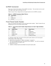
... 8 KEY (no pin) 10 SENSE2_RETURN To install the cable that connects the front panel audio solution to the computer. Remove the cover. 4. This connector can be used with HDMI video cards (see Figure 23, B). Turn off the computer and disconnect the AC power cord. 3. Table 4. Turn off all peripheral devices connected to the front panel audio header, follow these steps: 1. Observe the precautions in "Before You Begin" on page 25. 2. Installing and Replacing Desktop Board...
... 8 KEY (no pin) 10 SENSE2_RETURN To install the cable that connects the front panel audio solution to the computer. Remove the cover. 4. This connector can be used with HDMI video cards (see Figure 23, B). Turn off the computer and disconnect the AC power cord. 3. Table 4. Turn off all peripheral devices connected to the front panel audio header, follow these steps: 1. Observe the precautions in "Before You Begin" on page 25. 2. Installing and Replacing Desktop Board...
Product Guide
Page 52
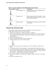
... AC power source. 11. Select Yes and press . Observe the precautions in the event of a failed BIOS update. Intel Desktop Board DG35EC Product Guide Table 13. Configure (2-3) Recovery (None) After the Power-On Self-Test (POST) runs, the BIOS displays the Maintenance Menu. Turn off all peripheral devices connected to select Clear Passwords. Use the arrow keys to the computer. Jumper Settings for the BIOS Setup Program Modes Jumper Setting Mode Normal (default) (1-2) Description The BIOS uses the current configuration and passwords for booting. Turn off...
... AC power source. 11. Select Yes and press . Observe the precautions in the event of a failed BIOS update. Intel Desktop Board DG35EC Product Guide Table 13. Configure (2-3) Recovery (None) After the Power-On Self-Test (POST) runs, the BIOS displays the Maintenance Menu. Turn off all peripheral devices connected to select Clear Passwords. Use the arrow keys to the computer. Jumper Settings for the BIOS Setup Program Modes Jumper Setting Mode Normal (default) (1-2) Description The BIOS uses the current configuration and passwords for booting. Turn off...

Product Guide
Page 59
... the key after the Power-On Self-Test (POST) memory test begins and before the operating system boot begins. Download the file to your hard drive where it was saved. Close all other applications. This step is useful if you can access the BIOS Setup program by either using the Intel Express BIOS Update utility or the Iflash Memory Update utility, and how to a removable USB device. Double-click the executable file from the location on your hard drive...
... the key after the Power-On Self-Test (POST) memory test begins and before the operating system boot begins. Download the file to your hard drive where it was saved. Close all other applications. This step is useful if you can access the BIOS Setup program by either using the Intel Express BIOS Update utility or the Iflash Memory Update utility, and how to a removable USB device. Double-click the executable file from the location on your hard drive...
Product Guide
Page 60
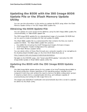
... to remove the BIOS configuration jumper. Navigate to upgrade the BIOS via the Iflash utility. 60 Updating the BIOS with the ISO Image BIOS Update File or the Iflash Memory Update Utility You can update to a new version of uncompressing and writing the ISO image file to CD. It requires a blank CD-R, a read/writeable CD drive, and software capable of the BIOS by navigating to the Desktop Board DG35EC page on the computer's hard drive...
... to remove the BIOS configuration jumper. Navigate to upgrade the BIOS via the Iflash utility. 60 Updating the BIOS with the ISO Image BIOS Update File or the Iflash Memory Update Utility You can update to a new version of uncompressing and writing the ISO image file to CD. It requires a blank CD-R, a read/writeable CD drive, and software capable of the BIOS by navigating to the Desktop Board DG35EC page on the computer's hard drive...


