
Product Specification
Page 5
... Memory Configurations 17 1.5 Intel® 945GC Chipset 17 1.5.1 Intel 945GC Graphics Subsystem 17 1.5.2 USB 19 1.5.3 IDE Support 19 1.5.4 Real-Time Clock, CMOS SRAM, and Battery 21 1.6 Legacy I/O Controller 21 1.6.1 Diskette Drive Controller 21 1.6.2 Keyboard and Mouse Interface 21 1.7 Audio Subsystem 22 1.7.1 Audio Subsystem Software 22 1.7.2 Audio Connectors 22 1.7.3 Four Channel Audio Subsystem 22 1.8 LAN Subsystem 23 1.8.1 LAN Subsystem Software 23 1.8.2 Realtek RTL8101E-GR Fast Ethernet Controller 24 1.9 Hardware Management Subsystem 25 1.9.1 Hardware Monitoring and Fan...
... Memory Configurations 17 1.5 Intel® 945GC Chipset 17 1.5.1 Intel 945GC Graphics Subsystem 17 1.5.2 USB 19 1.5.3 IDE Support 19 1.5.4 Real-Time Clock, CMOS SRAM, and Battery 21 1.6 Legacy I/O Controller 21 1.6.1 Diskette Drive Controller 21 1.6.2 Keyboard and Mouse Interface 21 1.7 Audio Subsystem 22 1.7.1 Audio Subsystem Software 22 1.7.2 Audio Connectors 22 1.7.3 Four Channel Audio Subsystem 22 1.8 LAN Subsystem 23 1.8.1 LAN Subsystem Software 23 1.8.2 Realtek RTL8101E-GR Fast Ethernet Controller 24 1.9 Hardware Management Subsystem 25 1.9.1 Hardware Monitoring and Fan...
Product Specification
Page 6
... PCI IDE Support 57 3.4 System Management BIOS (SMBIOS 57 3.5 BIOS Updates 58 3.5.1 Language Support 58 3.5.2 Custom Splash Screen 58 3.6 Legacy USB Support 59 3.7 Boot Options 59 3.7.1 CD-ROM Boot 59 3.7.2 Network Boot 59 3.7.3 Booting Without Attached Devices 60 3.7.4 Changing the Default Boot Device During POST 60 3.8 Adjusting Boot Speed 61 3.8.1 Peripheral Selection and Configuration 61 3.8.2 BIOS Boot Optimizations 61 3.9 BIOS Security Features 62 4 Error Messages and Beep Codes 4.1 BIOS Front-panel Power LED Codes 63 4.2 BIOS Error Messages 63 4.3 Port 80h POST Codes...
... PCI IDE Support 57 3.4 System Management BIOS (SMBIOS 57 3.5 BIOS Updates 58 3.5.1 Language Support 58 3.5.2 Custom Splash Screen 58 3.6 Legacy USB Support 59 3.7 Boot Options 59 3.7.1 CD-ROM Boot 59 3.7.2 Network Boot 59 3.7.3 Booting Without Attached Devices 60 3.7.4 Changing the Default Boot Device During POST 60 3.8 Adjusting Boot Speed 61 3.8.1 Peripheral Selection and Configuration 61 3.8.2 BIOS Boot Optimizations 61 3.9 BIOS Security Features 62 4 Error Messages and Beep Codes 4.1 BIOS Front-panel Power LED Codes 63 4.2 BIOS Error Messages 63 4.3 Port 80h POST Codes...

Product Specification
Page 7
... Header 43 19. BIOS Setup Program Menu Bar 56 27. Back Panel Audio Connector Options 23 4. Location of the Jumper Block 46 13. Location of the Standby Power Indicator LED 32 7. Localized High Temperature Zones 51 Tables 1. Component-side Connectors and Headers Shown in Figure 1 13 3. Serial Port Header 40 13. Processor Core Power Connector 42 17. Boot Device Menu Options 60 vii LAN Connector LED Locations 24 5. Power States and Targeted System Power 28 7. Wake-up Devices and Events 29 8. Main Power Connector 41 16. Auxiliary Front Panel Power/Sleep LED Header...
... Header 43 19. BIOS Setup Program Menu Bar 56 27. Back Panel Audio Connector Options 23 4. Location of the Jumper Block 46 13. Location of the Standby Power Indicator LED 32 7. Localized High Temperature Zones 51 Tables 1. Component-side Connectors and Headers Shown in Figure 1 13 3. Serial Port Header 40 13. Processor Core Power Connector 42 17. Boot Device Menu Options 60 vii LAN Connector LED Locations 24 5. Power States and Targeted System Power 28 7. Wake-up Devices and Events 29 8. Main Power Connector 41 16. Auxiliary Front Panel Power/Sleep LED Header...

Product Specification
Page 8
Port 80h POST Code Ranges 64 33. Lead-Free Board Markings 74 37. BIOS Error Messages 63 32. Port 80h POST Codes 65 34. Product Certification Markings 76 viii Supervisor and User Password Functions 62 30. EMC Regulations 75 38. Front-panel Power LED Blink Codes 63 31. Safety Standards 69 36. Intel Desktop Board D945GCPE Technical Product Specification 29. Typical Port 80h POST Sequence 68 35.
Port 80h POST Code Ranges 64 33. Lead-Free Board Markings 74 37. BIOS Error Messages 63 32. Port 80h POST Codes 65 34. Product Certification Markings 76 viii Supervisor and User Password Functions 62 30. EMC Regulations 75 38. Front-panel Power LED Blink Codes 63 31. Safety Standards 69 36. Intel Desktop Board D945GCPE Technical Product Specification 29. Typical Port 80h POST Sequence 68 35.
Product Specification
Page 10
... I/O Controller Hub (ICH7) Intel® Graphics Media Accelerator 950 (Intel® GMA950) onboard graphics subsystem Audio Legacy I/O Control Peripheral Interfaces LAN Support BIOS Expansion Capabilities Four channel (2 + 2) High Definition audio subsystem using the Realtek* ALC662 audio codec ITE 8718F/GX legacy I/O controller for diskette drive, serial header, and PS/2* ports • Eight USB 2.0 ports • Two Serial ATA interfaces • One Parallel ATA IDE interface with a 533 MHz system bus • Two 240-pin DDR2 SDRAM Dual Inline Memory Module (DIMM) sockets...
... I/O Controller Hub (ICH7) Intel® Graphics Media Accelerator 950 (Intel® GMA950) onboard graphics subsystem Audio Legacy I/O Control Peripheral Interfaces LAN Support BIOS Expansion Capabilities Four channel (2 + 2) High Definition audio subsystem using the Realtek* ALC662 audio codec ITE 8718F/GX legacy I/O controller for diskette drive, serial header, and PS/2* ports • Eight USB 2.0 ports • Two Serial ATA interfaces • One Parallel ATA IDE interface with a 533 MHz system bus • Two 240-pin DDR2 SDRAM Dual Inline Memory Module (DIMM) sockets...

Product Specification
Page 13
...audio header B PCI Conventional bus add-in card connector #2 C PCI Conventional bus add-in card connector #1 D Rear chassis fan header E Back panel connectors F Processor core power connector (2 X 2) G Intel 82945GC GMCH H LGA775 processor socket I Processor fan header J DIMM socket K DIMM socket L Main Power connector (2 X 12) M Diskette drive connector N Parallel ATE IDE connector O Battery P Serial ATA connectors [2] Q Auxiliary front panel power LED header R Front panel header S BIOS Setup configuration jumper block T Chassis intrusion header U Intel...
...audio header B PCI Conventional bus add-in card connector #2 C PCI Conventional bus add-in card connector #1 D Rear chassis fan header E Back panel connectors F Processor core power connector (2 X 2) G Intel 82945GC GMCH H LGA775 processor socket I Processor fan header J DIMM socket K DIMM socket L Main Power connector (2 X 12) M Diskette drive connector N Parallel ATE IDE connector O Battery P Serial ATA connectors [2] Q Auxiliary front panel power LED header R Front panel header S BIOS Setup configuration jumper block T Chassis intrusion header U Intel...

Product Specification
Page 15
... bus • Intel Celeron processor 400-series in an LGA775 socket with an 800 MHz system bus • Intel Celeron D processor in an LGA775 socket with a 533 MHz system bus See the Intel web site listed below for the Desktop Board D945GCPE Supported processors Chipset information BIOS and driver updates Tested Memory Visit this World Wide Web site: http://www.intel.com/products/motherboard/D945GCPE/index.htm http://support.intel.com/support/motherboards/desktop http://www.intel.com/products/motherboard...
... bus • Intel Celeron processor 400-series in an LGA775 socket with an 800 MHz system bus • Intel Celeron D processor in an LGA775 socket with a 533 MHz system bus See the Intel web site listed below for the Desktop Board D945GCPE Supported processors Chipset information BIOS and driver updates Tested Memory Visit this World Wide Web site: http://www.intel.com/products/motherboard/D945GCPE/index.htm http://support.intel.com/support/motherboards/desktop http://www.intel.com/products/motherboard...

Product Specification
Page 20
...: DMA protocol on IDE bus supporting host and target throttling and transfer rates of up to the BIOS. NOTE Many Serial ATA drives use new low-voltage power connectors and require adaptors or power supplies equipped with a theoretical maximum transfer rate of two Serial ATA devices. Intel Desktop Board D945GCPE Technical Product Specification 1.5.3.1 Parallel ATE IDE Interface The ICH7's Parallel ATA IDE controller has one bus-mastering Parallel ATA IDE interface. The ICH7...
...: DMA protocol on IDE bus supporting host and target throttling and transfer rates of up to the BIOS. NOTE Many Serial ATA drives use new low-voltage power connectors and require adaptors or power supplies equipped with a theoretical maximum transfer rate of two Serial ATA devices. Intel Desktop Board D945GCPE Technical Product Specification 1.5.3.1 Parallel ATE IDE Interface The ICH7's Parallel ATA IDE controller has one bus-mastering Parallel ATA IDE interface. The ICH7...
Product Specification
Page 23
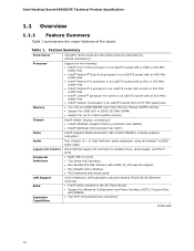
... 1.8 LAN Subsystem The LAN subsystem consists of the following: • Intel 82801GB ICH7 • Realtek RTL8101E-GR device for 10/100 Mbits/sec Ethernet LAN connectivity • RJ-45 LAN connector with integrated status LEDs Additional features of the LAN subsystem include: • CSMA/CD protocol engine • LAN connect interface that supports the 82562G • PCI Conventional bus power management ⎯ Supports ACPI technology ⎯ Supports LAN wake capabilities 1.8.1 LAN Subsystem Software LAN software and drivers...
... 1.8 LAN Subsystem The LAN subsystem consists of the following: • Intel 82801GB ICH7 • Realtek RTL8101E-GR device for 10/100 Mbits/sec Ethernet LAN connectivity • RJ-45 LAN connector with integrated status LEDs Additional features of the LAN subsystem include: • CSMA/CD protocol engine • LAN connect interface that supports the 82562G • PCI Conventional bus power management ⎯ Supports ACPI technology ⎯ Supports LAN wake capabilities 1.8.1 LAN Subsystem Software LAN software and drivers...

Product Specification
Page 27
... support: ⎯ Power connector ⎯ Fan headers ⎯ LAN wake capabilities ⎯ Instantly Available PC technology ⎯ Wake from USB ⎯ Wake from PS/2 devices ⎯ Power Management Event signal (PME#) wake-up events (see Table 7 on page 29) • Support for a front panel power and sleep mode switch Table 5 lists the system states based on how long the power switch is pressed, depending on how ACPI is configured with this board requires an operating system that enables...
... support: ⎯ Power connector ⎯ Fan headers ⎯ LAN wake capabilities ⎯ Instantly Available PC technology ⎯ Wake from USB ⎯ Wake from PS/2 devices ⎯ Power Management Event signal (PME#) wake-up events (see Table 7 on page 29) • Support for a front panel power and sleep mode switch Table 5 lists the system states based on how long the power switch is pressed, depending on how ACPI is configured with this board requires an operating system that enables...
Product Specification
Page 35
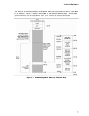
Figure 7. Detailed System Memory Address Map 35 All installed system memory can be used will vary based on add-in cards and BIOS settings. Figure 7 shows a schematic of system addresses. Technical Reference The amount of installed memory that can be used when there is no overlap of the system memory map.
Figure 7. Detailed System Memory Address Map 35 All installed system memory can be used will vary based on add-in cards and BIOS settings. Figure 7 shows a schematic of system addresses. Technical Reference The amount of installed memory that can be used when there is no overlap of the system memory map.

Product Specification
Page 36
... and should connect only to the computer, the power cable, and the external devices themselves. This section describes the board's connectors and headers. A fault in the load presented by the external devices could cause damage to devices inside the computer's chassis, such as fans and internal peripherals. Intel Desktop Board D945GCPE Technical Product Specification 2.2 Connectors and Headers CAUTION Only the following connectors and headers have overcurrent protection: back panel USB, front panel USB, and PS...
... and should connect only to the computer, the power cable, and the external devices themselves. This section describes the board's connectors and headers. A fault in the load presented by the external devices could cause damage to devices inside the computer's chassis, such as fans and internal peripherals. Intel Desktop Board D945GCPE Technical Product Specification 2.2 Connectors and Headers CAUTION Only the following connectors and headers have overcurrent protection: back panel USB, front panel USB, and PS...
Product Specification
Page 55
... PCI auto-configuration utility, and Plug and Play support. When the BIOS Setup configuration jumper is stored in configure mode. 3 Overview of BIOS and a revision code. The menu bar is in the Serial Peripheral Interface Flash Memory (SPI Flash) and can be updated using a disk-based program. The initial production BIOSs are identified as PE94510M.86A. The BIOS Setup program can be used to view and change the BIOS settings for the computer. The BIOS displays a message during POST identifying the type...
... PCI auto-configuration utility, and Plug and Play support. When the BIOS Setup configuration jumper is stored in configure mode. 3 Overview of BIOS and a revision code. The menu bar is in the Serial Peripheral Interface Flash Memory (SPI Flash) and can be updated using a disk-based program. The initial production BIOSs are identified as PE94510M.86A. The BIOS Setup program can be used to view and change the BIOS settings for the computer. The BIOS displays a message during POST identifying the type...

Product Specification
Page 56
... 27. Table 26. Autoconfiguration lets a user insert or remove PCI cards without having to Setup program options Table 27 lists the function keys available for menu screens. BIOS Setup Program Menu Bar Maintenance Clears passwords and displays processor information Main Advanced Displays processor and memory configuration Configures advanced features available through the chipset Security Sets passwords and security features Power Boot Configures power management features and power supply controls Selects boot options Exit Saves or discards changes to configure the system.
... 27. Table 26. Autoconfiguration lets a user insert or remove PCI cards without having to Setup program options Table 27 lists the function keys available for menu screens. BIOS Setup Program Menu Bar Maintenance Clears passwords and displays processor information Main Advanced Displays processor and memory configuration Configures advanced features available through the chipset Security Sets passwords and security features Power Boot Configures power management features and power supply controls Selects boot options Exit Saves or discards changes to configure the system.
Product Specification
Page 57
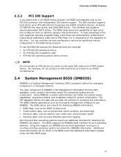
... management software to optimize capacity and performance. To take advantage of the high capacities typically available today, hard drives are required: • An ATA-66/100 peripheral device • An ATA-66/100 compatible cable • ATA-66/100 operating system device drivers NOTE Do not connect an ATA device as a slave on the capability of the drive. Overview of BIOS Features 3.3.2 PCI IDE Support If...
... management software to optimize capacity and performance. To take advantage of the high capacities typically available today, hard drives are required: • An ATA-66/100 peripheral device • An ATA-66/100 compatible cable • ATA-66/100 operating system device drivers NOTE Do not connect an ATA device as a slave on the capability of the drive. Overview of BIOS Features 3.3.2 PCI IDE Support If...

Product Specification
Page 59
... first boot device, the hard drive second, and the ATAPI CD-ROM third. After the operating system loads the USB drivers, all legacy and non-legacy USB devices are defined in the CD-ROM drive, the system will attempt to enter and configure the BIOS Setup program and the maintenance menu. 4. Pressing the key during POST, the User Access Level in compliance to install an operating system that supports USB, follow the operating system's installation instructions. 3.7 Boot Options In the BIOS Setup...
... first boot device, the hard drive second, and the ATAPI CD-ROM third. After the operating system loads the USB drivers, all legacy and non-legacy USB devices are defined in the CD-ROM drive, the system will attempt to enter and configure the BIOS Setup program and the maintenance menu. 4. Pressing the key during POST, the User Access Level in compliance to install an operating system that supports USB, follow the operating system's installation instructions. 3.7 Boot Options In the BIOS Setup...
Product Specification
Page 62
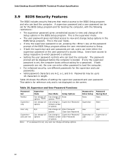
... Can change all None options (Note) options (Note) Supervisor only Can change all options Can change a Supervisor Password limited number of options User only N/A Can change all Enter Password options Clear User Password Supervisor and user set Can change all options Can change all Setup options. Intel Desktop Board D945GCPE Technical Product Specification 3.9 BIOS Security Features The BIOS includes security features that restrict access to 16 characters in length. The password prompt will be displayed before the computer is not displayed on the screen. Passwords...
... Can change all None options (Note) options (Note) Supervisor only Can change all options Can change a Supervisor Password limited number of options User only N/A Can change all Enter Password options Clear User Password Supervisor and user set Can change all options Can change all Setup options. Intel Desktop Board D945GCPE Technical Product Specification 3.9 BIOS Security Features The BIOS includes security features that restrict access to 16 characters in length. The password prompt will be displayed before the computer is not displayed on the screen. Passwords...

Product Specification
Page 63
... (four on-off (0.5 second each . CMOS memory may be bad. Off when update begins, then on -off . Table 31. Replace the battery soon. Memory size has decreased since the last boot. Front-panel Power LED Blink Codes Type Pattern Processor initialization complete POST complete BIOS update in progress Video error Memory error Thermal warning On when system powers up , then off for 0.5 second when processor initialization is powered off blink pattern; repeat entire pattern...
... (four on-off (0.5 second each . CMOS memory may be bad. Off when update begins, then on -off . Table 31. Replace the battery soon. Memory size has decreased since the last boot. Front-panel Power LED Blink Codes Type Pattern Processor initialization complete POST complete BIOS update in progress Video error Memory error Thermal warning On when system powers up , then off for 0.5 second when processor initialization is powered off blink pattern; repeat entire pattern...

Product Specification
Page 64
... future use . Boot device selection. EE: Miscellaneous codes. EF: boot/S3 resume failure. Intel Desktop Board D945GCPE Technical Product Specification 4.3 Port 80h POST Codes During the POST, the BIOS generates diagnostic progress codes (POST-codes) to I /O Busses: PCI, USB, ATA, etc. 5F is an unrecoverable error. Reserved for debug. BF is left at port 80h. NOTE The POST card must be used by the BIOS: • Table 32 lists the Port 80h POST code ranges • Table 33 lists the Port 80h POST codes...
... future use . Boot device selection. EE: Miscellaneous codes. EF: boot/S3 resume failure. Intel Desktop Board D945GCPE Technical Product Specification 4.3 Port 80h POST Codes During the POST, the BIOS generates diagnostic progress codes (POST-codes) to I /O Busses: PCI, USB, ATA, etc. 5F is an unrecoverable error. Reserved for debug. BF is left at port 80h. NOTE The POST card must be used by the BIOS: • Table 32 lists the Port 80h POST code ranges • Table 33 lists the Port 80h POST codes...

Product Specification
Page 65
... the memory controller and the DIMMs Configuring memory Optimizing memory settings Initializing memory, such as ECC init Testing memory PCI Bus Enumerating PCI busses Allocating resources to PCI bus Hot Plug PCI controller initialization Reserved for PCI Bus USB Resetting USB bus Reserved for USB ATA/ATAPI/SATA Resetting PATA/SATA bus and all devices Reserved for ATA SMBus Resetting SMBUS Reserved for SMBUS Local Console Resetting the VGA controller Disabling the VGA controller Enabling the VGA controller Remote Console Resetting the console controller Disabling the console controller Enabling...
... the memory controller and the DIMMs Configuring memory Optimizing memory settings Initializing memory, such as ECC init Testing memory PCI Bus Enumerating PCI busses Allocating resources to PCI bus Hot Plug PCI controller initialization Reserved for PCI Bus USB Resetting USB bus Reserved for USB ATA/ATAPI/SATA Resetting PATA/SATA bus and all devices Reserved for ATA SMBus Resetting SMBUS Reserved for SMBUS Local Console Resetting the VGA controller Disabling the VGA controller Enabling the VGA controller Remote Console Resetting the console controller Disabling the console controller Enabling...


