Product Specification
Page 5
...10 1.1.2 Board Layout 12 1.1.3 Block Diagram 14 1.2 Online Support 15 1.3 Processor 15 1.4 System Memory 16 1.4.1 Memory Configurations 18 1.5 Intel® 945G Chipset 20 1.5.1 Intel 945G Graphics Subsystem 20 1.5.2 USB 22 1.5.3 IDE Support 23 1.5.4 Real-Time Clock, CMOS SRAM, and Battery 24 1.6 PCI Express* Connectors 24 1.7 Legacy I/O Controller 25 1.7.1 Serial Port 25 1.7.2 Parallel Port 25 1.7.3 Diskette Drive Controller 25 1.7.4 Keyboard and Mouse Interface 25 1.8 Audio Subsystem 26 1.8.1 Audio Subsystem Software 26 1.8.2 Audio Connectors 26 1.8.3 6-Channel (5.1) Audio...
...10 1.1.2 Board Layout 12 1.1.3 Block Diagram 14 1.2 Online Support 15 1.3 Processor 15 1.4 System Memory 16 1.4.1 Memory Configurations 18 1.5 Intel® 945G Chipset 20 1.5.1 Intel 945G Graphics Subsystem 20 1.5.2 USB 22 1.5.3 IDE Support 23 1.5.4 Real-Time Clock, CMOS SRAM, and Battery 24 1.6 PCI Express* Connectors 24 1.7 Legacy I/O Controller 25 1.7.1 Serial Port 25 1.7.2 Parallel Port 25 1.7.3 Diskette Drive Controller 25 1.7.4 Keyboard and Mouse Interface 25 1.8 Audio Subsystem 26 1.8.1 Audio Subsystem Software 26 1.8.2 Audio Connectors 26 1.8.3 6-Channel (5.1) Audio...
Product Specification
Page 6
... PCI IDE Support 66 3.4 System Management BIOS (SMBIOS 67 3.5 BIOS Updates 68 3.5.1 Language Support 68 3.5.2 Custom Splash Screen 68 3.6 Legacy USB Support 69 3.7 Boot Options 69 3.7.1 CD-ROM Boot 69 3.7.2 Network Boot 69 3.7.3 Booting Without Attached Devices 70 3.7.4 Changing the Default Boot Device During POST 70 3.8 Adjusting Boot Speed 71 3.8.1 Peripheral Selection and Configuration 71 3.8.2 BIOS Boot Optimizations 71 3.9 BIOS Security Features 72 4 Error Messages and Beep Codes 4.1 Speaker 73 4.2 BIOS Beep Codes 73 4.3 BIOS Error Messages 73 4.4 Port 80h POST Codes...
... PCI IDE Support 66 3.4 System Management BIOS (SMBIOS 67 3.5 BIOS Updates 68 3.5.1 Language Support 68 3.5.2 Custom Splash Screen 68 3.6 Legacy USB Support 69 3.7 Boot Options 69 3.7.1 CD-ROM Boot 69 3.7.2 Network Boot 69 3.7.3 Booting Without Attached Devices 70 3.7.4 Changing the Default Boot Device During POST 70 3.8 Adjusting Boot Speed 71 3.8.1 Peripheral Selection and Configuration 71 3.8.2 BIOS Boot Optimizations 71 3.9 BIOS Security Features 72 4 Error Messages and Beep Codes 4.1 Speaker 73 4.2 BIOS Beep Codes 73 4.3 BIOS Error Messages 73 4.4 Port 80h POST Codes...
Product Specification
Page 7
.../Back Panel Audio Connector Options 27 8. LAN Connector LED Locations 29 9. Detailed System Memory Address Map 40 12. Memory Operating Frequencies 17 5. Wake-up Devices and Events 34 9. I /O Shield Dimensions 58 19. PCI Interrupt Routing Map 45 vii Dual Channel (Interleaved) Mode Configuration with One DIMM .......... 19 6. Thermal Sensors and Fan Headers 31 10. Location of the Jumper Block 56 17. Back Panel Connectors 47 13. Location of the Standby Power Indicator LED 37 11. Board Dimensions 57...
.../Back Panel Audio Connector Options 27 8. LAN Connector LED Locations 29 9. Detailed System Memory Address Map 40 12. Memory Operating Frequencies 17 5. Wake-up Devices and Events 34 9. I /O Shield Dimensions 58 19. PCI Interrupt Routing Map 45 vii Dual Channel (Interleaved) Mode Configuration with One DIMM .......... 19 6. Thermal Sensors and Fan Headers 31 10. Location of the Jumper Block 56 17. Back Panel Connectors 47 13. Location of the Standby Power Indicator LED 37 11. Board Dimensions 57...
Product Specification
Page 8
... Chassis Fan Headers 50 21. Auxiliary Front Panel Power/Sleep LED Header 52 24. BIOS Setup Configuration Jumper Settings 56 28. Thermal Considerations for a Two-Color Power LED 54 27. BIOS Error Messages 73 38. Port 80h POST Codes 75 40. Lead-Free Board Markings 84 43. Front Panel Audio Header 50 17. Front Panel Header 53 25. States for Components 63 31. DC Loading Characteristics 59 29. Beep Codes 73 37. Port 80h POST Code Ranges 74 39. Processor Fan Header 50 20. Processor Core Power Connector 51 23. Boot Device Menu Options...
... Chassis Fan Headers 50 21. Auxiliary Front Panel Power/Sleep LED Header 52 24. BIOS Setup Configuration Jumper Settings 56 28. Thermal Considerations for a Two-Color Power LED 54 27. BIOS Error Messages 73 38. Port 80h POST Codes 75 40. Lead-Free Board Markings 84 43. Front Panel Audio Header 50 17. Front Panel Header 53 25. States for Components 63 31. DC Loading Characteristics 59 29. Beep Codes 73 37. Port 80h POST Code Ranges 74 39. Processor Fan Header 50 20. Processor Core Power Connector 51 23. Boot Device Menu Options...
Product Specification
Page 10
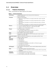
... diskette drive interface • PS/2 keyboard and mouse ports 10/100 Mbits/sec LAN subsystem using the Intel® 82562G Platform LAN Connect (PLC) device • Intel® BIOS (resident in the SPI Flash device) • Support for Advanced Configuration and Power Interface (ACPI), Plug and Play, and SMBIOS • Two PCI Conventional* bus connectors • One PCI Express* x1 bus add-in card connector • One PCI Express x16 bus add-in card connector continued 10 Feature Summary Form Factor Processor Memory Chipset Video Audio Legacy I/O Control microATX...
... diskette drive interface • PS/2 keyboard and mouse ports 10/100 Mbits/sec LAN subsystem using the Intel® 82562G Platform LAN Connect (PLC) device • Intel® BIOS (resident in the SPI Flash device) • Support for Advanced Configuration and Power Interface (ACPI), Plug and Play, and SMBIOS • Two PCI Conventional* bus connectors • One PCI Express* x1 bus add-in card connector • One PCI Express x16 bus add-in card connector continued 10 Feature Summary Form Factor Processor Memory Chipset Video Audio Legacy I/O Control microATX...

Product Specification
Page 13
... card connector D Back panel connectors E Processor core power connector F Rear chassis fan header G LGA775 processor socket H Intel 82945G GMCH I Processor fan header J DIMM sockets K Main Power connector L Diskette drive connector M Parallel ATE IDE connector N Battery O Front chassis fan header P BIOS Setup configuration jumper block Q Chassis intrusion header R Serial ATA connectors [4] S Auxiliary front panel power LED header T Front panel header U Front panel USB headers [2] V Intel 82801GB I/O Controller Hub (ICH7) W Speaker X PCI Express x1 bus...
... card connector D Back panel connectors E Processor core power connector F Rear chassis fan header G LGA775 processor socket H Intel 82945G GMCH I Processor fan header J DIMM sockets K Main Power connector L Diskette drive connector M Parallel ATE IDE connector N Battery O Front chassis fan header P BIOS Setup configuration jumper block Q Chassis intrusion header R Serial ATA connectors [4] S Auxiliary front panel power LED header T Front panel header U Front panel USB headers [2] V Intel 82801GB I/O Controller Hub (ICH7) W Speaker X PCI Express x1 bus...
Product Specification
Page 14
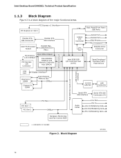
... Graphics and Memory Controller Hub (GMCH) USB Back Panel/Front Panel USB Ports Legacy I/O Controller LPC Bus Serial Port Parallel Port PS/2 Mouse PS/2 Keyboard Diskette Drive Connector Intel 82801GB I/O Controller Hub (ICH7) Serial Peripheral Interface (SPI) Flash Device DMI Interconnect High Definition Audio Link LAN Connect Interface VGA Port Display Interface Channel A DIMM Dual-Channel Memory Bus SMBus Channel B DIMM 10/100 LAN PLC LAN Connector Serial ATA IDE Interface Serial ATA IDE Connectors (4) PCI Slot 1 PCI Slot 2 PCI Bus SMBus Hardware Monitoring and Fan Control...
... Graphics and Memory Controller Hub (GMCH) USB Back Panel/Front Panel USB Ports Legacy I/O Controller LPC Bus Serial Port Parallel Port PS/2 Mouse PS/2 Keyboard Diskette Drive Connector Intel 82801GB I/O Controller Hub (ICH7) Serial Peripheral Interface (SPI) Flash Device DMI Interconnect High Definition Audio Link LAN Connect Interface VGA Port Display Interface Channel A DIMM Dual-Channel Memory Bus SMBus Channel B DIMM 10/100 LAN PLC LAN Connector Serial ATA IDE Interface Serial ATA IDE Connectors (4) PCI Slot 1 PCI Slot 2 PCI Bus SMBus Hardware Monitoring and Fan Control...

Product Specification
Page 16
... DIMMs NOTES • Remove the PCI Express x16 video card before installing or upgrading memory to Section 2.1.1 on page 39 for optimum performance. Table 3. If nonSPD memory is installed, the BIOS will attempt to accurately configure memory settings for information on the total amount of SDRAM). 16 This allows the BIOS to read the SPD data and program the chipset to correctly configure the memory settings, but performance and...
... DIMMs NOTES • Remove the PCI Express x16 video card before installing or upgrading memory to Section 2.1.1 on page 39 for optimum performance. Table 3. If nonSPD memory is installed, the BIOS will attempt to accurately configure memory settings for information on the total amount of SDRAM). 16 This allows the BIOS to read the SPD data and program the chipset to correctly configure the memory settings, but performance and...
Product Specification
Page 20
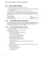
... graphics capabilities supporting 3D, 2D and display capabilities. The ICH7 is disabled. 1.5.1.1 Intel® GMA950 Graphics Controller The Intel GMA950 graphics controller features the following devices: • Intel 82945G Graphics Memory Controller Hub (GMCH) with Direct Media Interface (DMI) interconnect • Intel 82801GB I /O paths. When a PCI Express x16 add-in card can be used by the chipset Refer to the CPU, memory, PCI Express, and the DMI interconnect. Intel Desktop Board D945GCL Technical Product Specification 1.5 Intel® 945G Chipset The Intel 945G chipset...
... graphics capabilities supporting 3D, 2D and display capabilities. The ICH7 is disabled. 1.5.1.1 Intel® GMA950 Graphics Controller The Intel GMA950 graphics controller features the following devices: • Intel 82945G Graphics Memory Controller Hub (GMCH) with Direct Media Interface (DMI) interconnect • Intel 82801GB I /O paths. When a PCI Express x16 add-in card can be used by the chipset Refer to the CPU, memory, PCI Express, and the DMI interconnect. Intel Desktop Board D945GCL Technical Product Specification 1.5 Intel® 945G Chipset The Intel 945G chipset...
Product Specification
Page 28
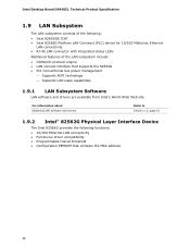
Intel Desktop Board D945GCL Technical Product Specification 1.9 LAN Subsystem The LAN subsystem consists of the following functions: • 10/100 Ethernet LAN connectivity • Full device driver compatibility • Programmable transit threshold • Configuration EEPROM that supports the 82562G • PCI Conventional bus power management ⎯ Supports ACPI technology ⎯ Supports LAN wake capabilities 1.9.1 LAN Subsystem Software LAN software and drivers are available from Intel's World Wide Web site. For information about Obtaining LAN software and drivers Refer ...
Intel Desktop Board D945GCL Technical Product Specification 1.9 LAN Subsystem The LAN subsystem consists of the following functions: • 10/100 Ethernet LAN connectivity • Full device driver compatibility • Programmable transit threshold • Configuration EEPROM that supports the 82562G • PCI Conventional bus power management ⎯ Supports ACPI technology ⎯ Supports LAN wake capabilities 1.9.1 LAN Subsystem Software LAN software and drivers are available from Intel's World Wide Web site. For information about Obtaining LAN software and drivers Refer ...

Product Specification
Page 34
... fully support ACPI wake events. 1.11.2 Hardware Support CAUTION Ensure that the power supply provides adequate +5 V standby current if LAN wake capabilities and Instantly Available PC technology features are used. The board provides several power management hardware features, including: • Power connector • Fan headers • LAN wake capabilities • Instantly Available PC technology • Resume on the wake devices supported and manufacturing options. Setting this state S1, S3, S4, S5 (Note) Modem (back panel Serial Port...
... fully support ACPI wake events. 1.11.2 Hardware Support CAUTION Ensure that the power supply provides adequate +5 V standby current if LAN wake capabilities and Instantly Available PC technology features are used. The board provides several power management hardware features, including: • Power connector • Fan headers • LAN wake capabilities • Instantly Available PC technology • Resume on the wake devices supported and manufacturing options. Setting this state S1, S3, S4, S5 (Note) Modem (back panel Serial Port...
Product Specification
Page 39
... registers, internal graphics ranges, PCI Express ports (up to system address space being allocated for PCI Conventional bus add-in cards and BIOS settings. On a system that can be used when there is no overlap of system addresses. 39 All installed system memory can be used will vary based on add-in cards, PCI Express configuration space, BIOS (SPI Flash), and chipset overhead resides above the top of DRAM (total system memory). Figure...
... registers, internal graphics ranges, PCI Express ports (up to system address space being allocated for PCI Conventional bus add-in cards and BIOS settings. On a system that can be used when there is no overlap of system addresses. 39 All installed system memory can be used will vary based on add-in cards, PCI Express configuration space, BIOS (SPI Flash), and chipset overhead resides above the top of DRAM (total system memory). Figure...

Product Specification
Page 43
... 2.4 PCI Configuration Space Map Table 12. Bus number is installed. 2. PCI Configuration Space Map Bus Device Function Number (hex) Number (hex) Number (hex) Description 00 00 00 Memory controller of Intel 82945G component 00 01 00 PCI Express x16 graphics port (Note 1) 00 02 00 Integrated graphics controller 00 1B 00 Intel High Definition Audio Controller 00 1C 00 PCI Express port 1 00 1C 01 PCI Express port 2 00 1C 02 PCI Express port 3 00 1C 03 PCI Express port 4 00 1D 00 USB...
... 2.4 PCI Configuration Space Map Table 12. Bus number is installed. 2. PCI Configuration Space Map Bus Device Function Number (hex) Number (hex) Number (hex) Description 00 00 00 Memory controller of Intel 82945G component 00 01 00 PCI Express x16 graphics port (Note 1) 00 02 00 Integrated graphics controller 00 1B 00 Intel High Definition Audio Controller 00 1C 00 PCI Express port 1 00 1C 01 PCI Express port 2 00 1C 02 PCI Express port 3 00 1C 03 PCI Express port 4 00 1D 00 USB...
Product Specification
Page 46
... these connectors/headers to power devices external to the computer's chassis. A fault in the load presented by the external devices could cause damage to devices inside the computer's chassis, such as fans and internal peripherals. This section describes the board's connectors and headers. Intel Desktop Board D945GCL Technical Product Specification 2.7 Connectors and Headers CAUTION Only the following connectors have overcurrent protection: back panel USB, front panel USB, and PS/2. Do not use these groups: • Back panel connectors...
... these connectors/headers to power devices external to the computer's chassis. A fault in the load presented by the external devices could cause damage to devices inside the computer's chassis, such as fans and internal peripherals. This section describes the board's connectors and headers. Intel Desktop Board D945GCL Technical Product Specification 2.7 Connectors and Headers CAUTION Only the following connectors have overcurrent protection: back panel USB, front panel USB, and PS/2. Do not use these groups: • Back panel connectors...

Product Specification
Page 65
... BIOS Setup configuration jumper is set to view and change the BIOS settings for the computer. The BIOS displays a message during POST identifying the type of BIOS Features What This Chapter Contains 3.1 Introduction 65 3.2 BIOS Flash Memory Organization 66 3.3 Resource Configuration 66 3.4 System Management BIOS (SMBIOS 67 3.5 BIOS Updates 68 3.6 Legacy USB Support 69 3.7 Boot Options 69 3.8 Adjusting Boot Speed 71 3.9 BIOS Security Features 72 3.1 Introduction The boards use an Intel BIOS that is shown below. The menu bar is stored in the Serial...
... BIOS Setup configuration jumper is set to view and change the BIOS settings for the computer. The BIOS displays a message during POST identifying the type of BIOS Features What This Chapter Contains 3.1 Introduction 65 3.2 BIOS Flash Memory Organization 66 3.3 Resource Configuration 66 3.4 System Management BIOS (SMBIOS 67 3.5 BIOS Updates 68 3.6 Legacy USB Support 69 3.7 Boot Options 69 3.8 Adjusting Boot Speed 71 3.9 BIOS Security Features 72 3.1 Introduction The boards use an Intel BIOS that is shown below. The menu bar is stored in the Serial...

Product Specification
Page 66
... compliant devices, including CD-ROM drives, tape drives, and Ultra DMA drives. The BIOS determines the capabilities of each drive 66 BIOS Setup Program Menu Bar Maintenance Clears passwords and displays processor information Main Advanced Displays processor and memory configuration Configures advanced features available through the chipset Security Sets passwords and security features Power Boot Configures power management features and power supply controls Selects boot options Exit Saves or discards changes to configure the system. Intel Desktop Board D945GCL Technical...
... compliant devices, including CD-ROM drives, tape drives, and Ultra DMA drives. The BIOS determines the capabilities of each drive 66 BIOS Setup Program Menu Bar Maintenance Clears passwords and displays processor information Main Advanced Displays processor and memory configuration Configures advanced features available through the chipset Security Sets passwords and security features Power Boot Configures power management features and power supply controls Selects boot options Exit Saves or discards changes to configure the system. Intel Desktop Board D945GCL Technical...

Product Specification
Page 67
... support, an SMBIOS service-level application running on the same IDE cable as Windows NT*, require an additional interface for managing computers in the BIOS Setup program. To use SMBIOS. To take advantage of the high capacities typically available today, hard drives are required: • An ATA-66/100 peripheral device • An ATA-66/100 compatible cable • ATA-66/100 operating system device drivers...
... support, an SMBIOS service-level application running on the same IDE cable as Windows NT*, require an additional interface for managing computers in the BIOS Setup program. To use SMBIOS. To take advantage of the high capacities typically available today, hard drives are required: • An ATA-66/100 peripheral device • An ATA-66/100 compatible cable • ATA-66/100 operating system device drivers...
Product Specification
Page 69
... The default setting is loading, USB keyboards and mice are recognized and may be used even when the operating system's USB drivers are not yet available. To use a USB keyboard to install an operating system that supports USB, follow the operating system's installation instructions. 3.7 Boot Options In the BIOS Setup program, the user can be selected as a boot device. This selection allows booting from a diskette drive, hard drives, CD-ROM, or the network. Legacy USB support operates as a boot device. Under the Boot menu in the BIOS Setup...
... The default setting is loading, USB keyboards and mice are recognized and may be used even when the operating system's USB drivers are not yet available. To use a USB keyboard to install an operating system that supports USB, follow the operating system's installation instructions. 3.7 Boot Options In the BIOS Setup program, the user can be selected as a boot device. This selection allows booting from a diskette drive, hard drives, CD-ROM, or the network. Legacy USB support operates as a boot device. Under the Boot menu in the BIOS Setup...
Product Specification
Page 74
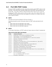
... an unrecoverable error. Boot device selection. Host Processors: 1F is useful for future use . Reserved for new busses). Reserved for future use (for future use (new output console codes). Boot Devices: Includes fixed media and removable media. See Table 39. Displaying the POST-codes requires a PCI bus add-in PCI bus connector 1. NOTE The POST card must be used by the BIOS: • Table 38 lists the Port 80h POST code ranges • Table 39 lists the Port 80h POST codes themselves...
... an unrecoverable error. Boot device selection. Host Processors: 1F is useful for future use . Reserved for new busses). Reserved for future use (for future use (new output console codes). Boot Devices: Includes fixed media and removable media. See Table 39. Displaying the POST-codes requires a PCI bus add-in PCI bus connector 1. NOTE The POST card must be used by the BIOS: • Table 38 lists the Port 80h POST code ranges • Table 39 lists the Port 80h POST codes themselves...

Product Specification
Page 75
... POST Operation Host Processor Power-on initialization of the host processor (Boot Strap Processor) Host processor Cache initialization (including APs) Starting Application processor initialization SMM initialization Chipset Initializing a chipset component Memory Reading SPD from memory DIMMs Detecting presence of memory DIMMs Programming timing parameters in the memory controller and the DIMMs Configuring memory Optimizing memory settings Initializing memory, such as ECC init Testing memory PCI Bus Enumerating PCI busses Allocating resources to PCI bus Hot Plug PCI controller initialization...
... POST Operation Host Processor Power-on initialization of the host processor (Boot Strap Processor) Host processor Cache initialization (including APs) Starting Application processor initialization SMM initialization Chipset Initializing a chipset component Memory Reading SPD from memory DIMMs Detecting presence of memory DIMMs Programming timing parameters in the memory controller and the DIMMs Configuring memory Optimizing memory settings Initializing memory, such as ECC init Testing memory PCI Bus Enumerating PCI busses Allocating resources to PCI bus Hot Plug PCI controller initialization...


