Product Guide
Page 3
... as Information Technology Equipment (I.T.E.) for use in this manual: CAUTION Cautions warn the user about BIOS error messages, beep codes, and POST codes B Regulatory Compliance: describes the board's adherence to safety standards and EMC regulations and its product certifications Conventions The following conventions are evaluated as medical, industrial, alarm systems, test equipment, etc. Use Only for Intended Applications All Intel Desktop Boards are used in personal...
... as Information Technology Equipment (I.T.E.) for use in this manual: CAUTION Cautions warn the user about BIOS error messages, beep codes, and POST codes B Regulatory Compliance: describes the board's adherence to safety standards and EMC regulations and its product certifications Conventions The following conventions are evaluated as medical, industrial, alarm systems, test equipment, etc. Use Only for Intended Applications All Intel Desktop Boards are used in personal...
Product Guide
Page 5
... Chipset 14 Audio Subsystem 14 LAN Subsystem 15 USB 2.0 Support 16 Hard Disk and Optical Disk Drive Support 16 Enhanced IDE Interface 16 Serial ATA 17 Disk Drive Access Indicator 18 Legacy I/O ...18 Expandability...19 BIOS ...19 Serial ATA and IDE Auto Configuration 19 PCI and PCI Express* Auto Configuration 19 Security Passwords 19 Hardware Management 20 Hardware Monitoring and Fan Speed Control 20 Intel® Precision Cooling Technology 20 Chassis Intrusion 20 Power Management 21 Software Support 21 ACPI 21 Hardware Support 21 Power Connectors 21 Fan Headers 22 LAN Wake...
... Chipset 14 Audio Subsystem 14 LAN Subsystem 15 USB 2.0 Support 16 Hard Disk and Optical Disk Drive Support 16 Enhanced IDE Interface 16 Serial ATA 17 Disk Drive Access Indicator 18 Legacy I/O ...18 Expandability...19 BIOS ...19 Serial ATA and IDE Auto Configuration 19 PCI and PCI Express* Auto Configuration 19 Security Passwords 19 Hardware Management 20 Hardware Monitoring and Fan Speed Control 20 Intel® Precision Cooling Technology 20 Chassis Intrusion 20 Power Management 21 Software Support 21 ACPI 21 Hardware Support 21 Power Connectors 21 Fan Headers 22 LAN Wake...
Product Guide
Page 6
... Card 43 Installing Multiple Graphics Cards 44 Connecting the IDE Cable 44 Connecting the SATA Cables 46 Connecting to the Internal Headers and Connectors 47 HD Audio Link Header 48 S/PDIF Connector 48 Front Panel Audio Header 49 IEEE 1394a Header 49 Front Panel Header 49 USB 2.0 Headers 50 Consumer IR (CIR) Headers 50 Chassis Intrusion Header 51 Connecting to the Flexible Audio System 52 Connecting Chassis Fan and Power Supply Cables 53 Connecting Chassis Fan Cables 53 Connecting Power Supply Cables 54 Setting the BIOS Configuration Jumper 55 Clearing Passwords 56 Replacing...
... Card 43 Installing Multiple Graphics Cards 44 Connecting the IDE Cable 44 Connecting the SATA Cables 46 Connecting to the Internal Headers and Connectors 47 HD Audio Link Header 48 S/PDIF Connector 48 Front Panel Audio Header 49 IEEE 1394a Header 49 Front Panel Header 49 USB 2.0 Headers 50 Consumer IR (CIR) Headers 50 Chassis Intrusion Header 51 Connecting to the Flexible Audio System 52 Connecting Chassis Fan and Power Supply Cables 53 Connecting Chassis Fan Cables 53 Connecting Power Supply Cables 54 Setting the BIOS Configuration Jumper 55 Clearing Passwords 56 Replacing...
Product Guide
Page 7
.... Processor Fan Heat Sink Headers 37 16. Back Panel Audio Connectors 52 25. Location of the BIOS Configuration Jumper Block 55 vii Installing the I/O Shield 31 8. Install the Processor 35 14. Removing a PCI Express x16 Card 43 21. Remove the Processor from the Protective Processor Cover 35 13. Connecting Power Supply Cables 54 27. Internal Headers and Connectors 47 24. LAN Status LEDs 15 3. Location of the VR and CPU LEDs 27 7. Lift the Socket Lever 33 10. Connecting the IDE Cable 45 22. Onboard Power and Reset Buttons 26...
.... Processor Fan Heat Sink Headers 37 16. Back Panel Audio Connectors 52 25. Location of the BIOS Configuration Jumper Block 55 vii Installing the I/O Shield 31 8. Install the Processor 35 14. Removing a PCI Express x16 Card 43 21. Remove the Processor from the Protective Processor Cover 35 13. Connecting Power Supply Cables 54 27. Internal Headers and Connectors 47 24. LAN Status LEDs 15 3. Location of the VR and CPU LEDs 27 7. Lift the Socket Lever 33 10. Connecting the IDE Cable 45 22. Onboard Power and Reset Buttons 26...
Product Guide
Page 10
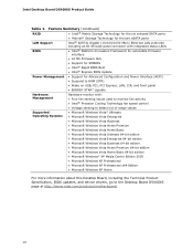
...; Intel® Rapid BIOS Boot • Intel® Express BIOS Update Power Management • Support for Advanced Configuration and Power Interface (ACPI) • Suspend to RAM (STR) • Wake on USB, PCI, PCI Express, LAN, CIR, and front panel • ENERGY STAR* capable Hardware Management Hardware monitor with: • Four fan sensing inputs used to monitor fan activity • Intel® Precision Cooling Technology fan speed control • Voltage sensing to detect out of range values Supported Operating Systems • Microsoft Windows Vista...
...; Intel® Rapid BIOS Boot • Intel® Express BIOS Update Power Management • Support for Advanced Configuration and Power Interface (ACPI) • Suspend to RAM (STR) • Wake on USB, PCI, PCI Express, LAN, CIR, and front panel • ENERGY STAR* capable Hardware Management Hardware monitor with: • Four fan sensing inputs used to monitor fan activity • Intel® Precision Cooling Technology fan speed control • Voltage sensing to detect out of range values Supported Operating Systems • Microsoft Windows Vista...
Product Guide
Page 12
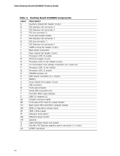
... 12 V processor core voltage connectors (2 x 4 pin) (2) Processor (CPU 1) fan header Processor (CPU 1) socket FBDIMM sockets (4) Main power connector (2 x 12 pin) Battery Front chassis fan header (3-pin) IDE connector Front panel header Serial ATA connectors (6) Port 80h POST code indicator USB 2.0 headers (2) Chassis intrusion header Front panel CIR receiver (input) header Back panel CIR transmitter (output) header BIOS configuration jumper block IEEE 1394a header Onboard reset button Onboard power button Speaker High Definition Audio Link header Auxiliary PCI Express graphics power connector...
... 12 V processor core voltage connectors (2 x 4 pin) (2) Processor (CPU 1) fan header Processor (CPU 1) socket FBDIMM sockets (4) Main power connector (2 x 12 pin) Battery Front chassis fan header (3-pin) IDE connector Front panel header Serial ATA connectors (6) Port 80h POST code indicator USB 2.0 headers (2) Chassis intrusion header Front panel CIR receiver (input) header Back panel CIR transmitter (output) header BIOS configuration jumper block IEEE 1394a header Onboard reset button Onboard power button Speaker High Definition Audio Link header Auxiliary PCI Express graphics power connector...
Product Guide
Page 13
... "Installing a DIMM Cooling Fan" on page 41 in Chapter 2 for use an appropriate power supply and/or not connecting the 12 V (2 x 4 pin) power connectors to the Desktop Board may result in damage to the board, or the system may not function properly. Desktop Board Features Processors CAUTION Failure to use on Desktop Board D5400XS. Processors are not included with the Desktop Board and must be populated with all applicable Intel ® SDRAM memory specifications, the board...
... "Installing a DIMM Cooling Fan" on page 41 in Chapter 2 for use an appropriate power supply and/or not connecting the 12 V (2 x 4 pin) power connectors to the Desktop Board may result in damage to the board, or the system may not function properly. Desktop Board Features Processors CAUTION Failure to use on Desktop Board D5400XS. Processors are not included with the Desktop Board and must be populated with all applicable Intel ® SDRAM memory specifications, the board...
Product Guide
Page 14
...-to the processors, memory, and the PCI Express bus and the Intel 6321ESB I/O Controller Hub is a centralized controller for HDMI video cards that can be used for the board's I /O Controller Hub The MCH provides interfaces to -noise (S/N) ratio of 95 dB • Independent multi-streaming 8-channel (7.1) audio (using the back panel audio connectors) and 2-channel audio (using the Intel High Definition Audio front panel header) • ADAT optical interface support via the back panel S/PDIF optical port 14 Intel Desktop Board D5400XS Product Guide Related...
...-to the processors, memory, and the PCI Express bus and the Intel 6321ESB I/O Controller Hub is a centralized controller for HDMI video cards that can be used for the board's I /O Controller Hub The MCH provides interfaces to -noise (S/N) ratio of 95 dB • Independent multi-streaming 8-channel (7.1) audio (using the back panel audio connectors) and 2-channel audio (using the Intel High Definition Audio front panel header) • ADAT optical interface support via the back panel S/PDIF optical port 14 Intel Desktop Board D5400XS Product Guide Related...
Product Guide
Page 19
... IDE device (such as a hard drive) in your computer, the auto-configuration utility in the Serial Peripheral Interface (SPI) Flash device. The password prompt is displayed before the computer is set , you can boot the computer. If both the supervisor and user passwords are set , the computer boots without asking for viewing and changing depending on whether the supervisor or user password was entered. • Setting a user password restricts who can be updated by specifying manual configuration in card...
... IDE device (such as a hard drive) in your computer, the auto-configuration utility in the Serial Peripheral Interface (SPI) Flash device. The password prompt is displayed before the computer is set , you can boot the computer. If both the supervisor and user passwords are set , the computer boots without asking for viewing and changing depending on whether the supervisor or user password was entered. • Setting a user password restricts who can be updated by specifying manual configuration in card...
Product Guide
Page 21
... location of the power connectors. 21 The computer's response can turn off ). Software Support ACPI ACPI gives the operating system direct control over the power management and Plug and Play functions of ACPI with the Desktop Board requires an operating system that provides full ACPI support. When an ACPI-enabled computer receives the correct command, the power supply removes all non-standby voltages. When resuming from USB • Power Management Event (PME#) signal wake-up support...
... location of the power connectors. 21 The computer's response can turn off ). Software Support ACPI ACPI gives the operating system direct control over the power management and Plug and Play functions of ACPI with the Desktop Board requires an operating system that provides full ACPI support. When an ACPI-enabled computer receives the correct command, the power supply removes all non-standby voltages. When resuming from USB • Power Management Event (PME#) signal wake-up support...
Product Guide
Page 23
... (ACPI S3 sleep state) configuration. Failure to provide adequate standby current when using this Desktop Board must be off. Failure to do so could damage the board and any devices connected to enter the ACPI S3 (Suspend-toRAM) sleep state. Instantly Available PC technology enables the board to the board. Add-in cards that support this green LED is lit, standby power is still present at the memory module sockets and the PCI bus and PCI Express bus connectors. 23 Desktop Board...
... (ACPI S3 sleep state) configuration. Failure to provide adequate standby current when using this Desktop Board must be off. Failure to do so could damage the board and any devices connected to enter the ACPI S3 (Suspend-toRAM) sleep state. Instantly Available PC technology enables the board to the board. Add-in cards that support this green LED is lit, standby power is still present at the memory module sockets and the PCI bus and PCI Express bus connectors. 23 Desktop Board...
Product Guide
Page 29
...2 Installing and Replacing Desktop Board Components This chapter tells you how to: • Install the I/O shield • Install and remove the Desktop Board • Install a processor • Install an MCH heat sink fan • Install and remove memory • Install and remove a PCI Express x16 card • Connect the IDE and Serial ATA cables • Connect to the internal headers and connectors • Connect to the audio system • Connect chassis fan and power supply cables • Set the BIOS configuration jumper • Clear passwords • Replace the battery Before...
...2 Installing and Replacing Desktop Board Components This chapter tells you how to: • Install the I/O shield • Install and remove the Desktop Board • Install a processor • Install an MCH heat sink fan • Install and remove memory • Install and remove a PCI Express x16 card • Connect the IDE and Serial ATA cables • Connect to the internal headers and connectors • Connect to the audio system • Connect chassis fan and power supply cables • Set the BIOS configuration jumper • Clear passwords • Replace the battery Before...
Product Guide
Page 44
... supplied by the graphics card manufacturer or visit their website. If an ATA-66/100 disk drive and a disk drive using any other IDE transfer protocol are backward compatible with the Desktop Board to the Desktop Board using slower IDE transfer protocols. For correct function of the slowest drive. Intel Desktop Board D5400XS Product Guide Installing Multiple Graphics Cards The Desktop Board supports technology that of the cable: • Observe the precautions in the PCI Express x16 connectors, refer to the card manufacturer's instructions...
... supplied by the graphics card manufacturer or visit their website. If an ATA-66/100 disk drive and a disk drive using any other IDE transfer protocol are backward compatible with the Desktop Board to the Desktop Board using slower IDE transfer protocols. For correct function of the slowest drive. Intel Desktop Board D5400XS Product Guide Installing Multiple Graphics Cards The Desktop Board supports technology that of the cable: • Observe the precautions in the PCI Express x16 connectors, refer to the card manufacturer's instructions...
Product Guide
Page 50
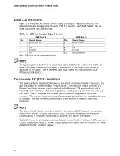
... translated infrared input compliant with Microsoft CIR specifications and a "learning" infrared input. USB 2.0 Header Signal Names USB Port A Pin Signal Name Pin 1 Power (+5 V) 2 3 D- 4 5 D+ 6 7 Ground 8 9 Key 10 Note: USB ports may be used to speak the infrared communication language of the USB 2.0 headers. Press at boot to enter the system BIOS, and go to Advanced > Peripheral Configuration > Enhanced Consumer IR, and set this option to emulate "learned" infrared commands in the...
... translated infrared input compliant with Microsoft CIR specifications and a "learning" infrared input. USB 2.0 Header Signal Names USB Port A Pin Signal Name Pin 1 Power (+5 V) 2 3 D- 4 5 D+ 6 7 Ground 8 9 Key 10 Note: USB ports may be used to speak the infrared communication language of the USB 2.0 headers. Press at boot to enter the system BIOS, and go to Advanced > Peripheral Configuration > Enhanced Consumer IR, and set this option to emulate "learned" infrared commands in the...

Product Guide
Page 56
... BIOS Setup program. Jumper Settings for the BIOS Setup Program Modes Jumper Setting Mode Normal (default) (1-2) Description The BIOS uses the current configuration and passwords for the BIOS Setup program modes. Setup displays the Maintenance menu. 8. Use the arrow keys to save the current values and exit Setup. 10. Use this menu to boot. 7. Remove the computer cover. 4. Table 13. Disconnect the computer's power cord from the AC power source. 56 Replace the cover, plug in the event of a failed BIOS update. The computer starts...
... BIOS Setup program. Jumper Settings for the BIOS Setup Program Modes Jumper Setting Mode Normal (default) (1-2) Description The BIOS uses the current configuration and passwords for the BIOS Setup program modes. Setup displays the Maintenance menu. 8. Use the arrow keys to save the current values and exit Setup. 10. Use this menu to boot. 7. Remove the computer cover. 4. Table 13. Disconnect the computer's power cord from the AC power source. 56 Replace the cover, plug in the event of a failed BIOS update. The computer starts...

Product Guide
Page 63
... view and change the BIOS settings for multiple identical systems.) 4. Your system will be used to complete the BIOS update. 63 The BIOS file is useful if you are updating the BIOS for the computer. Navigate to a removable USB device. This chapter tells you can access the BIOS Setup program by either using the Intel Express BIOS Update utility or the Iflash Memory Update utility, and how to the Intel World Wide Web site: http://support.intel.com/support/motherboards/desktop/ 2. Close...
... view and change the BIOS settings for multiple identical systems.) 4. Your system will be used to complete the BIOS update. 63 The BIOS file is useful if you are updating the BIOS for the computer. Navigate to a removable USB device. This chapter tells you can access the BIOS Setup program by either using the Intel Express BIOS Update utility or the Iflash Memory Update utility, and how to the Intel World Wide Web site: http://support.intel.com/support/motherboards/desktop/ 2. Close...
Product Guide
Page 64
... Configuration File (optional) • Intel Flash Memory Update Utility You can update to create a bootable CD that will update the BIOS. Navigate to the Desktop Board D5400XS page on the computer's hard drive and without the need to CD. It requires a blank CD-R, a read/writeable CD drive, and software capable of uncompressing and writing the ISO image file to update the BIOS. The Iflash BIOS update file is a standardized image of a bootable CD-ROM...
... Configuration File (optional) • Intel Flash Memory Update Utility You can update to create a bootable CD that will update the BIOS. Navigate to the Desktop Board D5400XS page on the computer's hard drive and without the need to CD. It requires a blank CD-R, a read/writeable CD drive, and software capable of uncompressing and writing the ISO image file to update the BIOS. The Iflash BIOS update file is a standardized image of a bootable CD-ROM...

Product Guide
Page 68
... manage the RAID configuration. Begin Windows Setup by pressing the key after downloading it from the Windows installation CD. 2. Configuring for information on selecting a compatible USB floppy disk drive. At the beginning of Windows Setup, press to Advanced Peripheral Configuration Secondary SATA Controller; Refer to the system. Finish the Windows installation and install all necessary drivers. 4. Install the Intel Matrix Storage Console software via the Intel Express Installer CD included with your Desktop Board or after the Power-On-Self-Test (POST) memory tests begin...
... manage the RAID configuration. Begin Windows Setup by pressing the key after downloading it from the Windows installation CD. 2. Configuring for information on selecting a compatible USB floppy disk drive. At the beginning of Windows Setup, press to Advanced Peripheral Configuration Secondary SATA Controller; Refer to the system. Finish the Windows installation and install all necessary drivers. 4. Install the Intel Matrix Storage Console software via the Intel Express Installer CD included with your Desktop Board or after the Power-On-Self-Test (POST) memory tests begin...

Product Guide
Page 69
... and enter the RAID Configuration Utility. 2. Refer to install a third-party SCSI or RAID driver. Exit the Option ROM user interface by booting from the Windows installation CD. 2. In the Marvell Storage Manager option ROM Main Menu, select: Create RAID Volume. Use the arrow keys to Create Volume. 7. Finally, press to select RAID 0 or RAID 1. Configuring for information on selecting a compatible USB floppy disk drive. Enter the size of Windows Setup, press to http://support.microsoft.com/kb/916196/en-us for RAID Creating Your RAID Set...
... and enter the RAID Configuration Utility. 2. Refer to install a third-party SCSI or RAID driver. Exit the Option ROM user interface by booting from the Windows installation CD. 2. In the Marvell Storage Manager option ROM Main Menu, select: Create RAID Volume. Use the arrow keys to Create Volume. 7. Finally, press to select RAID 0 or RAID 1. Configuring for information on selecting a compatible USB floppy disk drive. Enter the size of Windows Setup, press to http://support.microsoft.com/kb/916196/en-us for RAID Creating Your RAID Set...
Product Guide
Page 75
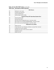
... the password E9 Entering BIOS setup EB Calling Legacy Option ROMs Runtime Phase/EFI Operating System Boot F4 Entering Sleep state F5 Exiting Sleep state F8 EFI boot service ExitBootServices( ) has been called F9 EFI runtime service SetVirtualAddressMap( ) has been called FA EFI runtime service ResetSystem( ) has been called PEIMs/Recovery/Wake 30 Wake from S3 31 Crisis Recovery has initiated by software (corrupt Flash memory) 34 Loading the recovery capsule 35 Handing off control...
... the password E9 Entering BIOS setup EB Calling Legacy Option ROMs Runtime Phase/EFI Operating System Boot F4 Entering Sleep state F5 Exiting Sleep state F8 EFI boot service ExitBootServices( ) has been called F9 EFI runtime service SetVirtualAddressMap( ) has been called FA EFI runtime service ResetSystem( ) has been called PEIMs/Recovery/Wake 30 Wake from S3 31 Crisis Recovery has initiated by software (corrupt Flash memory) 34 Loading the recovery capsule 35 Handing off control...


