Product Guide
Page 3
...for use in personal computers (PC) for installation in this product for Intel® Desktop Board D410PT. iii NOTE Notes call attention to hardware or loss of how to update the BIOS A BIOS Error Messages: information about board layout, component installation, and regulatory requirements ...how to install the Desktop Board and other hardware components 3 Updating the BIOS: a description of data. Intended Audience The Product Guide is not intended for technically qualified personnel. Intended Uses All Intel® Desktop Boards are arranged as medical, industrial, alarm systems, test ...
...for use in personal computers (PC) for installation in this product for Intel® Desktop Board D410PT. iii NOTE Notes call attention to hardware or loss of how to update the BIOS A BIOS Error Messages: information about board layout, component installation, and regulatory requirements ...how to install the Desktop Board and other hardware components 3 Updating the BIOS: a description of data. Intended Audience The Product Guide is not intended for technically qualified personnel. Intended Uses All Intel® Desktop Boards are arranged as medical, industrial, alarm systems, test ...
Product Guide
Page 5
... 11 Processor ...13 System Memory 13 Integrated Graphics Subsystem 14 Intel® NM10 Express Chipset 14 Operating System Support 14 Onboard Audio Subsystem 14 Legacy Input/Output (I/O) Controller 16 LAN Subsystem 16 USB 2.0 Support 17 SATA Interface 17 Expandability...17 BIOS ...18 PCI Auto Configuration 18 Security Passwords 18 Power Management... Front Panel Header 34 Connecting to the Front Panel USB 2.0 Headers 35 Connecting a Chassis Fan 35 Connecting the Power Supply Cable 36 Setting the BIOS Configuration Jumper 37 Clearing Passwords 38 Replacing the Battery 39 v
... 11 Processor ...13 System Memory 13 Integrated Graphics Subsystem 14 Intel® NM10 Express Chipset 14 Operating System Support 14 Onboard Audio Subsystem 14 Legacy Input/Output (I/O) Controller 16 LAN Subsystem 16 USB 2.0 Support 17 SATA Interface 17 Expandability...17 BIOS ...18 PCI Auto Configuration 18 Security Passwords 18 Power Management... Front Panel Header 34 Connecting to the Front Panel USB 2.0 Headers 35 Connecting a Chassis Fan 35 Connecting the Power Supply Cable 36 Setting the BIOS Configuration Jumper 37 Clearing Passwords 38 Replacing the Battery 39 v
Product Guide
Page 6
... Product Guide 3 Updating the BIOS Updating the BIOS with the Intel® Express BIOS Update Utility 45 Updating the BIOS with the Iflash Memory Update Utility 46 Obtaining the BIOS Update File 46 Using the Iflash Memory Update Utility 46 Recovering the BIOS 47 A Board Status and Error Messages BIOS Beep Codes 49 BIOS Front-panel Power LED Blink...
... Product Guide 3 Updating the BIOS Updating the BIOS with the Intel® Express BIOS Update Utility 45 Updating the BIOS with the Iflash Memory Update Utility 46 Obtaining the BIOS Update File 46 Using the Iflash Memory Update Utility 46 Recovering the BIOS 47 A Board Status and Error Messages BIOS Beep Codes 49 BIOS Front-panel Power LED Blink...

Product Guide
Page 7
...Location of the Chassis Fan Header 35 12. Intel Desktop Board D410PT China RoHS Material Self Declaration Table 58 Tables 1. Jumper Settings for Intel HD Audio 33 7. Installing a DIMM 29 9. Connecting a Serial ATA Cable 31 10. BIOS Configuration Jumper Block 37 14. Removing the Battery...-panel Power LED Blink Codes 50 15. Front Panel Audio Header for the BIOS Setup Program Modes 38 12. Intel Desktop Board D410PT Components 11 2. Back Panel Audio Connectors 15 3. Intel Desktop Board D410PT Mounting Screw Holes 27 7. Use DDR2 DIMMs 28 8. China RoHS...
...Location of the Chassis Fan Header 35 12. Intel Desktop Board D410PT China RoHS Material Self Declaration Table 58 Tables 1. Jumper Settings for Intel HD Audio 33 7. Installing a DIMM 29 9. Connecting a Serial ATA Cable 31 10. BIOS Configuration Jumper Block 37 14. Removing the Battery...-panel Power LED Blink Codes 50 15. Front Panel Audio Header for the BIOS Setup Program Modes 38 12. Intel Desktop Board D410PT Components 11 2. Back Panel Audio Connectors 15 3. Intel Desktop Board D410PT Mounting Screw Holes 27 7. Use DDR2 DIMMs 28 8. China RoHS...
Product Guide
Page 9
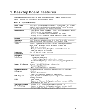
.../2 keyboard and mouse connectors Hardware monitoring through the Winbond legacy I /O Control Hardware Monitor Subsystem LAN Support BIOS Instantly Available PC Technology Mini-ITX ([170 millimeters [6.7 inches] x 170 millimeters [6.7 inches]) Passively-cooled, soldered-down single-core Intel® Atom™ processor with integrated graphics and memory controllers. • Two 240-pin Double Data...
.../2 keyboard and mouse connectors Hardware monitoring through the Winbond legacy I /O Control Hardware Monitor Subsystem LAN Support BIOS Instantly Available PC Technology Mini-ITX ([170 millimeters [6.7 inches] x 170 millimeters [6.7 inches]) Passively-cooled, soldered-down single-core Intel® Atom™ processor with integrated graphics and memory controllers. • Two 240-pin Double Data...

Product Guide
Page 10
.../products/motherboard/D410PT/index.htm Chipset information http://www.intel.com/products/desktop/chipsets/index.htm BIOS and driver updates http://downloadcenter.intel.com/ Integration information http://www.intel.com/support/go/buildit 10 Intel Desktop Board D410PT Product Guide For more information on Intel Desktop Board D410PT consult the following online resources: To find information...
.../products/motherboard/D410PT/index.htm Chipset information http://www.intel.com/products/desktop/chipsets/index.htm BIOS and driver updates http://downloadcenter.intel.com/ Integration information http://www.intel.com/support/go/buildit 10 Intel Desktop Board D410PT Product Guide For more information on Intel Desktop Board D410PT consult the following online resources: To find information...
Product Guide
Page 13
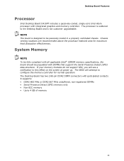
...DIMM connectors with DIMMs that support the Serial Presence Detect (SPD) data structure. System Memory NOTE To be fully compliant with all applicable Intel® SDRAM memory specifications, the board should be passively cooled in a properly ventilated chassis. If your memory modules do not support SPD,... you will attempt to configure the memory controller for maximum heat dissipation effectiveness. The BIOS will see a notification to 4 GB of memory 13 NOTE The board is designed to the Desktop Board and is soldered to be ...
...DIMM connectors with DIMMs that support the Serial Presence Detect (SPD) data structure. System Memory NOTE To be fully compliant with all applicable Intel® SDRAM memory specifications, the board should be passively cooled in a properly ventilated chassis. If your memory modules do not support SPD,... you will attempt to configure the memory controller for maximum heat dissipation effectiveness. The BIOS will see a notification to 4 GB of memory 13 NOTE The board is designed to the Desktop Board and is soldered to be ...

Product Guide
Page 16
... D410PT Product Guide Legacy Input/Output (I/O) Controller The legacy I/O controller provides the following : • Intel NM10 Express Chipset • Realtek RTL8103EL Ethernet Controller for 10/100 Mbits/s Ethernet LAN connectivity • RJ-45 LAN ...8226; PS/2-style keyboard and mouse ports • Intelligent power management, including a programmable wake up event interface • PCI power management support The BIOS Setup program provides configuration options for the legacy I/O controller. LAN Status LEDs 16 Figure 3. LAN Subsystem The LAN subsystem consists of the following : ...
... D410PT Product Guide Legacy Input/Output (I/O) Controller The legacy I/O controller provides the following : • Intel NM10 Express Chipset • Realtek RTL8103EL Ethernet Controller for 10/100 Mbits/s Ethernet LAN connectivity • RJ-45 LAN ...8226; PS/2-style keyboard and mouse ports • Intelligent power management, including a programmable wake up event interface • PCI power management support The BIOS Setup program provides configuration options for the legacy I/O controller. LAN Status LEDs 16 Figure 3. LAN Subsystem The LAN subsystem consists of the following : ...
Product Guide
Page 17
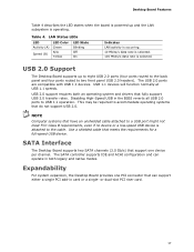
...-speed USB device is attached to the cable. The SATA controller supports IDE and ACHI configuration and can support either a single PCI add-in the BIOS reverts all USB 2.0 ports to USB 1.1 operation. Desktop Board Features Table 4 describes the LED states when the board is powered up to eight USB 2.0 ports...
...-speed USB device is attached to the cable. The SATA controller supports IDE and ACHI configuration and can support either a single PCI add-in the BIOS reverts all USB 2.0 ports to USB 1.1 operation. Desktop Board Features Table 4 describes the LED states when the board is powered up to eight USB 2.0 ports...

Product Guide
Page 18
...gives the user restricted access to Setup. • If both passwords are set , the computer boots without asking for that restrict whether the BIOS Setup program can be set , you must enter either password to view and change all Setup options. For instructions on resetting the password,... utility in card. You do not need to access Setup. Intel Desktop Board D410PT Product Guide BIOS The BIOS provides the Power-On Self-Test (POST), the BIOS Setup program, the PCI and IDE auto-configuration utilities, and the video BIOS. If only the supervisor password is set, pressing at several ...
...gives the user restricted access to Setup. • If both passwords are set , the computer boots without asking for that restrict whether the BIOS Setup program can be set , you must enter either password to view and change all Setup options. For instructions on resetting the password,... utility in card. You do not need to access Setup. Intel Desktop Board D410PT Product Guide BIOS The BIOS provides the Power-On Self-Test (POST), the BIOS Setup program, the PCI and IDE auto-configuration utilities, and the video BIOS. If only the supervisor password is set, pressing at several ...
Product Guide
Page 23
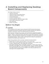
...; Install and remove system memory • Connect SATA drives • Connect to internal headers • Connect chassis fan and power supply cables • Set the BIOS configuration jumper • Clear passwords • Replace the battery Before You Begin CAUTION The procedures in this chapter. If such a station is off. Follow these...
...; Install and remove system memory • Connect SATA drives • Connect to internal headers • Connect chassis fan and power supply cables • Set the BIOS configuration jumper • Clear passwords • Replace the battery Before You Begin CAUTION The procedures in this chapter. If such a station is off. Follow these...

Product Guide
Page 37
Installing and Replacing Desktop Board Components Setting the BIOS Configuration Jumper NOTE Always turn off the power and unplug the power cord from the computer before changing a jumper. BIOS Configuration Jumper Block The three-pin BIOS jumper block enables board operating modes. Figure 13 shows the location of the available modes. 37 Moving the jumper with the power on may result in unreliable computer operation. Figure 13. Table 11 shows the jumper settings for each of the Desktop Board's BIOS configuration jumper block.
Installing and Replacing Desktop Board Components Setting the BIOS Configuration Jumper NOTE Always turn off the power and unplug the power cord from the computer before changing a jumper. BIOS Configuration Jumper Block The three-pin BIOS jumper block enables board operating modes. Figure 13 shows the location of the available modes. 37 Moving the jumper with the power on may result in unreliable computer operation. Figure 13. Table 11 shows the jumper settings for each of the Desktop Board's BIOS configuration jumper block.

Product Guide
Page 38
...cover. 4. Press to clear passwords. Remove the computer cover. 38 Configure (2-3) After the Power-On Self-Test (POST) runs, the BIOS displays the Maintenance Menu. Use this menu to save the current values and exit Setup. 10. Clearing Passwords This procedure assumes that you confirm...from a recovery diskette in the computer and the configuration jumper is installed in the event of a failed BIOS update. Turn off the computer. Use the arrow keys to the computer. Intel Desktop Board D410PT Product Guide Table 11. Place the jumper on page 23. 2. Observe the precautions in...
...cover. 4. Press to clear passwords. Remove the computer cover. 38 Configure (2-3) After the Power-On Self-Test (POST) runs, the BIOS displays the Maintenance Menu. Use this menu to save the current values and exit Setup. 10. Clearing Passwords This procedure assumes that you confirm...from a recovery diskette in the computer and the configuration jumper is installed in the event of a failed BIOS update. Turn off the computer. Use the arrow keys to the computer. Intel Desktop Board D410PT Product Guide Table 11. Place the jumper on page 23. 2. Observe the precautions in...
Product Guide
Page 39
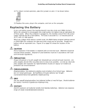
... för explosion om batteriet ersätts med felaktig batterityp. To restore normal operation, place the jumper on pins 1-2 as shown below a certain level, the BIOS Setup program settings stored in accordance with an incorrect type. Figure 14 on the computer. Batteries should be accurate. Brukte batterier bør kastes i henhold til...
... för explosion om batteriet ersätts med felaktig batterityp. To restore normal operation, place the jumper on pins 1-2 as shown below a certain level, the BIOS Setup program settings stored in accordance with an incorrect type. Figure 14 on the computer. Batteries should be accurate. Brukte batterier bør kastes i henhold til...

Product Guide
Page 45
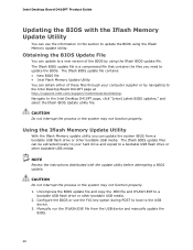
...the operating system boot begins. 3 Updating the BIOS The BIOS Setup program can be rebooted at the last Intel Express BIOS Update window. 5. You can also save this file to http://support.intel.com/support/motherboards/desktop/. 2. The BIOS file is required. Close all other applications. ...Your system will be used to the Intel Desktop Board D410PT page, click "[view] Latest BIOS updates," and select the Intel Express BIOS Update utility file. 3. Navigate to view and change the BIOS settings for multiple identical systems.) 4. This step is included ...
...the operating system boot begins. 3 Updating the BIOS The BIOS Setup program can be rebooted at the last Intel Express BIOS Update window. 5. You can also save this file to http://support.intel.com/support/motherboards/desktop/. 2. The BIOS file is required. Close all other applications. ...Your system will be used to the Intel Desktop Board D410PT page, click "[view] Latest BIOS updates," and select the Intel Express BIOS Update utility file. 3. Navigate to view and change the BIOS settings for multiple identical systems.) 4. This step is included ...
Product Guide
Page 46
...the F10 key option during POST to boot to the Intel Desktop D410PT page, click "[view] Latest BIOS updates," and select the Iflash BIOS Update utility file. Obtaining the BIOS Update File You can update to update the BIOS. The Iflash BIOS update file is a compressed file that contains the ...files you can update the system BIOS from the USB device and manually update the BIOS. 46 Uncompress the BIOS update file and copy the .BIO file and IFLASH.EXE to the Intel Desktop Board D410PT page at http://support.intel.com/support/motherboards/desktop. CAUTION Do not interrupt...
...the F10 key option during POST to boot to the Intel Desktop D410PT page, click "[view] Latest BIOS updates," and select the Iflash BIOS Update utility file. Obtaining the BIOS Update File You can update to update the BIOS. The Iflash BIOS update file is a compressed file that contains the ...files you can update the system BIOS from the USB device and manually update the BIOS. 46 Uncompress the BIOS update file and copy the .BIO file and IFLASH.EXE to the Intel Desktop Board D410PT page at http://support.intel.com/support/motherboards/desktop. CAUTION Do not interrupt...

Product Guide
Page 47
...disk drive Can be bootable. Yes Yes No No NOTE For more information about BIOS update and recovery, go to be Used for BIOS recovery. The BIOS recovery media does not have to http://support.intel.com/support/motherboards/desktop/sb/CS-022312.htm. 47 Table 12 lists the drives... and media types that anything will interrupt a BIOS update; Table 12. Updating the BIOS Recovering the BIOS It is unlikely that...
...disk drive Can be bootable. Yes Yes No No NOTE For more information about BIOS update and recovery, go to be Used for BIOS recovery. The BIOS recovery media does not have to http://support.intel.com/support/motherboards/desktop/sb/CS-022312.htm. 47 Table 12 lists the drives... and media types that anything will interrupt a BIOS update; Table 12. Updating the BIOS Recovering the BIOS It is unlikely that...
Product Guide
Page 49
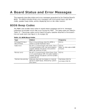
... the board's line out audio jack (see Figure 2, B on the video monitor. the entire pattern repeats (beeps and pause) once and the BIOS will continue to boot. 932 Hz When no VGA option ROM is ready to signal status messages and error messages indicating recoverable errors that occur... the entire pattern repeats (beeps and pause) until the system is powered off (1.0 second each ) for eight beeps, followed by the Desktop Board's BIOS. The BIOS indicates these error messages with front-panel Power LED blink codes, speaker beep codes, and by displaying text on page 15). Table 13.
... the board's line out audio jack (see Figure 2, B on the video monitor. the entire pattern repeats (beeps and pause) once and the BIOS will continue to boot. 932 Hz When no VGA option ROM is ready to signal status messages and error messages indicating recoverable errors that occur... the entire pattern repeats (beeps and pause) until the system is powered off (1.0 second each ) for eight beeps, followed by the Desktop Board's BIOS. The BIOS indicates these error messages with front-panel Power LED blink codes, speaker beep codes, and by displaying text on page 15). Table 13.

Product Guide
Page 50
... trip warning Pattern Note Off when the update begins, then on for 0.5 second. the entire pattern repeats (blinks and pause) until the BIOS update is powered off , 0.25 second on the video monitor when certain recoverable errors occur during the POST. On-off (1.0 second each)...second pause (off for 0.5 second, and then off ); Intel Desktop Board D410PT Product Guide BIOS Front-panel Power LED Blink Codes The BIOS also blinks the front-panel power LED to reset values. BIOS Front-panel Power LED Blink Codes Type BIOS update in Table 14. The CMOS checksum is incorrect. ...
... trip warning Pattern Note Off when the update begins, then on for 0.5 second. the entire pattern repeats (blinks and pause) until the BIOS update is powered off , 0.25 second on the video monitor when certain recoverable errors occur during the POST. On-off (1.0 second each)...second pause (off for 0.5 second, and then off ); Intel Desktop Board D410PT Product Guide BIOS Front-panel Power LED Blink Codes The BIOS also blinks the front-panel power LED to reset values. BIOS Front-panel Power LED Blink Codes Type BIOS update in Table 14. The CMOS checksum is incorrect. ...


