Product Specification
Page 8
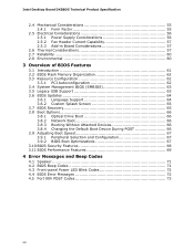
...3.5 Legacy USB Support 63 3.6 BIOS Updates 64 3.6.1 Language Support 64 3.6.2 Custom Splash Screen 65 3.7 BIOS Recovery 65 3.8 Boot Options 66 3.8.1 Optical Drive Boot 66 3.8.2 Network Boot 66 3.8.3 Booting Without Attached Devices 66 3.8.4 Changing the Default Boot Device During POST 66 3.9 Adjusting Boot Speed 67 3.9.1 Peripheral Selection and Configuration 67 3.9.2 BIOS Boot Optimizations 67 3.10 BIOS Security Features 68 3.11 BIOS Performance Features 69 4 Error Messages and Beep Codes 4.1 Speaker 71 4.2 BIOS Beep Codes 71 4.3 Front-panel Power LED Blink Codes 72 4.4 BIOS...
...3.5 Legacy USB Support 63 3.6 BIOS Updates 64 3.6.1 Language Support 64 3.6.2 Custom Splash Screen 65 3.7 BIOS Recovery 65 3.8 Boot Options 66 3.8.1 Optical Drive Boot 66 3.8.2 Network Boot 66 3.8.3 Booting Without Attached Devices 66 3.8.4 Changing the Default Boot Device During POST 66 3.9 Adjusting Boot Speed 67 3.9.1 Peripheral Selection and Configuration 67 3.9.2 BIOS Boot Optimizations 67 3.10 BIOS Security Features 68 3.11 BIOS Performance Features 69 4 Error Messages and Beep Codes 4.1 Speaker 71 4.2 BIOS Beep Codes 71 4.3 Front-panel Power LED Blink Codes 72 4.4 BIOS...
Product Specification
Page 10
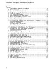
.... Power States and Targeted System Power 31 9. Front Panel Audio Header 45 13. Front Panel Header 50 23. Boot Device Menu Options 66 34. Typical Port 80h POST Sequence 77 41. Effects of Pressing the Power Switch 30 8. States for Components 59 29. BIOS Setup Configuration Jumper Settings 54 26. Recommended Power Supply Current Values 56 27. BIOS Beep Codes 71 36. Auxiliary Front Panel Power/Sleep LED Header 47 19. Thermal Considerations for a Two-Color Power LED 51 25. Auxiliary PCI Express Graphics Power Connector 49...
.... Power States and Targeted System Power 31 9. Front Panel Audio Header 45 13. Front Panel Header 50 23. Boot Device Menu Options 66 34. Typical Port 80h POST Sequence 77 41. Effects of Pressing the Power Switch 30 8. States for Components 59 29. BIOS Setup Configuration Jumper Settings 54 26. Recommended Power Supply Current Values 56 27. BIOS Beep Codes 71 36. Auxiliary Front Panel Power/Sleep LED Header 47 19. Thermal Considerations for a Two-Color Power LED 51 25. Auxiliary PCI Express Graphics Power Connector 49...
Product Specification
Page 11
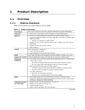
...-I legacy I /O Controller Hub (ICH10R) Intel® High Definition Audio subsystem using 4 Gb memory technology • Support for PCI Express* Revision 2.0 • Suspend to 24 GB of system memory with RAID support: ― Two SATA 6 Gb/s interfaces through Marvel 88SE9128 controller (blue) ― Six SATA 3 Gb/s interfaces through the ICH10R (black) • Two IEEE 1394a ports: ― One port via a back panel connector ― One port via an internal header for front panel cabling • Intel® BIOS resident...
...-I legacy I /O Controller Hub (ICH10R) Intel® High Definition Audio subsystem using 4 Gb memory technology • Support for PCI Express* Revision 2.0 • Suspend to 24 GB of system memory with RAID support: ― Two SATA 6 Gb/s interfaces through Marvel 88SE9128 controller (blue) ― Six SATA 3 Gb/s interfaces through the ICH10R (black) • Two IEEE 1394a ports: ― One port via a back panel connector ― One port via an internal header for front panel cabling • Intel® BIOS resident...
Product Specification
Page 16
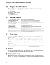
... for providing power to support the Intel Core i7 and Intel Xeon Processors in the future. This board is designed to ) the following: • No parallel port • No floppy drive connector • No serial port • No PS/2 connectors 1.3 Online Support To find information about ... Use of the Intel Desktop Board DX58OG. The processor listed above . For information about ... Intel Desktop Board DX58OG Technical Product Specification 1.2 Legacy Considerations This board differs from other Intel Desktop Board products, with specific changes including...
... for providing power to support the Intel Core i7 and Intel Xeon Processors in the future. This board is designed to ) the following: • No parallel port • No floppy drive connector • No serial port • No PS/2 connectors 1.3 Online Support To find information about ... Use of the Intel Desktop Board DX58OG. The processor listed above . For information about ... Intel Desktop Board DX58OG Technical Product Specification 1.2 Legacy Considerations This board differs from other Intel Desktop Board products, with specific changes including...
Product Specification
Page 18
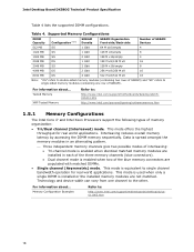
... memory latency by accessing the DIMM memory sequentially. For information about ... Intel Desktop Board DX58OG Technical Product Specification Table 4 lists the supported DIMM configurations. This mode is installed or the installed memory modules are not matched. Memory Configuration Examples Refer to single-sided memory modules (containing one channel to : http://www.intel.com/support/motherboards/desktop/sb/CS025414.htm http://www.intel.com/personal/gaming/extremememory.htm 1.5.1 Memory Configurations The Intel Core i7 and Intel Xeon Processors support the following types...
... memory latency by accessing the DIMM memory sequentially. For information about ... Intel Desktop Board DX58OG Technical Product Specification Table 4 lists the supported DIMM configurations. This mode is installed or the installed memory modules are not matched. Memory Configuration Examples Refer to single-sided memory modules (containing one channel to : http://www.intel.com/support/motherboards/desktop/sb/CS025414.htm http://www.intel.com/personal/gaming/extremememory.htm 1.5.1 Memory Configurations The Intel Core i7 and Intel Xeon Processors support the following types...
Product Specification
Page 21
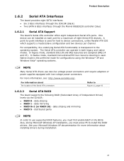
... to use new low-voltage power connectors and require adapters or power supplies equipped with low-voltage power connectors. For more information about The location of the Serial ATA connectors Refer to device connections, unlike Parallel ATA IDE which supports a master/slave configuration and two devices per channel. For information about installing drivers during Microsoft Windows XP installation, you must press F6 to the operating system. data striping and mirroring • RAID 5 - One device can...
... to use new low-voltage power connectors and require adapters or power supplies equipped with low-voltage power connectors. For more information about The location of the Serial ATA connectors Refer to device connections, unlike Parallel ATA IDE which supports a master/slave configuration and two devices per channel. For information about installing drivers during Microsoft Windows XP installation, you must press F6 to the operating system. data striping and mirroring • RAID 5 - One device can...
Product Specification
Page 22
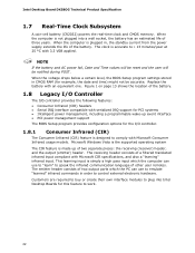
... be notified during POST. Intel Desktop Board DX58OG Technical Product Specification 1.7 Real-Time Clock Subsystem A coin-cell battery (CR2032) powers the real-time clock and CMOS memory. The emitter header consists of two output ports which the computer can use to "learn" to comply with Microsoft Consumer Infrared usage models. This learning input is plugged in CMOS RAM (for PCI systems • Intelligent power management, including a programmable wake-up of three...
... be notified during POST. Intel Desktop Board DX58OG Technical Product Specification 1.7 Real-Time Clock Subsystem A coin-cell battery (CR2032) powers the real-time clock and CMOS memory. The emitter header consists of two output ports which the computer can use to "learn" to comply with Microsoft Consumer Infrared usage models. This learning input is plugged in CMOS RAM (for PCI systems • Intelligent power management, including a programmable wake-up of three...
Product Specification
Page 25
... LAN connector with integrated status LEDs Additional features of the LAN subsystem include: • CSMA/CD protocol engine • LAN connect interface between ICH10R and the LAN controller • Conventional PCI bus power management ⎯ ACPI technology support ⎯ LAN wake capabilities • LAN subsystem software For information about LAN software and drivers Refer to http://downloadcenter.intel.com 1.10.1 Intel® 82567L Gigabit Ethernet Controller The Intel 82567L Gigabit Ethernet Controller support the following features: • PCI Express...
... LAN connector with integrated status LEDs Additional features of the LAN subsystem include: • CSMA/CD protocol engine • LAN connect interface between ICH10R and the LAN controller • Conventional PCI bus power management ⎯ ACPI technology support ⎯ LAN wake capabilities • LAN subsystem software For information about LAN software and drivers Refer to http://downloadcenter.intel.com 1.10.1 Intel® 82567L Gigabit Ethernet Controller The Intel 82567L Gigabit Ethernet Controller support the following features: • PCI Express...
Product Specification
Page 52
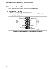
Connection Diagram for high-speed USB devices. Figure 13. Intel Desktop Board DX58OG Technical Product Specification 2.2.2.6 Front Panel USB Headers Figure 13 is a connection diagram for the front panel USB headers. # INTEGRATOR'S NOTES • The +5 V DC power on the USB headers is fused. • Use only a front panel USB connector that conforms to the USB 2.0 specification for Front Panel USB Headers 52
Connection Diagram for high-speed USB devices. Figure 13. Intel Desktop Board DX58OG Technical Product Specification 2.2.2.6 Front Panel USB Headers Figure 13 is a connection diagram for the front panel USB headers. # INTEGRATOR'S NOTES • The +5 V DC power on the USB headers is fused. • Use only a front panel USB connector that conforms to the USB 2.0 specification for Front Panel USB Headers 52
Product Specification
Page 61
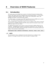
... Main Advanced Performance Security Power Boot Exit NOTE The maintenance menu is displayed only when the board is shown below. The SPI Flash contains the BIOS Setup program, POST, the PCI auto-configuration utility, LAN EEPROM information, and Plug and Play support. The menu bar is in configure mode. The initial production BIOSs are identified as SOX5810J.86A. When the BIOS Setup configuration jumper is set to put the board in configure mode. 61 The BIOS Setup program can be used...
... Main Advanced Performance Security Power Boot Exit NOTE The maintenance menu is displayed only when the board is shown below. The SPI Flash contains the BIOS Setup program, POST, the PCI auto-configuration utility, LAN EEPROM information, and Plug and Play support. The menu bar is in configure mode. The initial production BIOSs are identified as SOX5810J.86A. When the BIOS Setup configuration jumper is set to put the board in configure mode. 61 The BIOS Setup program can be used...
Product Specification
Page 62
...Security Clears passwords and displays processor information Displays processor and memory configuration Configures advanced features available through the chipset Configures Memory, Bus and Processor overrides Sets passwords and security features Power Configures power management features and power supply controls Boot Selects boot options Exit Saves or discards changes to configure the system. Intel Desktop Board DX58OG Technical Product Specification Table 30 lists the BIOS Setup program menu features. Table 30. When a user turns on the system after adding a PCI card, the BIOS...
...Security Clears passwords and displays processor information Displays processor and memory configuration Configures advanced features available through the chipset Configures Memory, Bus and Processor overrides Sets passwords and security features Power Configures power management features and power supply controls Boot Selects boot options Exit Saves or discards changes to configure the system. Intel Desktop Board DX58OG Technical Product Specification Table 30 lists the BIOS Setup program menu features. Table 30. When a user turns on the system after adding a PCI card, the BIOS...
Product Specification
Page 63
... Main BIOS page. 3.5 Legacy USB Support Legacy USB support enables USB devices to be found in a managed network. The BIOS enables applications such as third-party management software to use a USB keyboard to Disabled in the BIOS Setup program.) 6. By default, Legacy USB support is set to enter and configure the BIOS Setup program and the maintenance menu. 4. Legacy USB support operates as event detection and error logging Non-Plug and Play operating systems require an additional interface for system components. After the operating system loads the USB drivers...
... Main BIOS page. 3.5 Legacy USB Support Legacy USB support enables USB devices to be found in a managed network. The BIOS enables applications such as third-party management software to use a USB keyboard to Disabled in the BIOS Setup program.) 6. By default, Legacy USB support is set to enter and configure the BIOS Setup program and the maintenance menu. 4. Legacy USB support operates as event detection and error logging Non-Plug and Play operating systems require an additional interface for system components. After the operating system loads the USB drivers...
Product Specification
Page 66
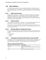
...the LAN. This menu displays the list of available boot devices (as a boot device. Boot devices are not present: • Video adapter • Keyboard • Mouse 3.8.4 Changing the Default Boot Device During POST Pressing the key during POST automatically forces booting from the onboard LAN or a network add-in card with a remote boot ROM installed. Pressing the key during POST causes a boot device menu to boot from the selected device Exits the menu without saving changes 66 Intel Desktop Board DX58OG Technical Product Specification 3.8 Boot Options In the BIOS Setup program...
...the LAN. This menu displays the list of available boot devices (as a boot device. Boot devices are not present: • Video adapter • Keyboard • Mouse 3.8.4 Changing the Default Boot Device During POST Pressing the key during POST automatically forces booting from the onboard LAN or a network add-in card with a remote boot ROM installed. Pressing the key during POST causes a boot device menu to boot from the selected device Exits the menu without saving changes 66 Intel Desktop Board DX58OG Technical Product Specification 3.8 Boot Options In the BIOS Setup program...
Product Specification
Page 68
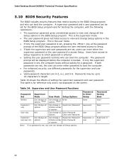
Intel Desktop Board DX58OG Technical Product Specification 3.10 BIOS Security Features The BIOS includes security features that restrict access to Enter Setup None Password During Boot None Supervisor None User User Supervisor or Supervisor or user user 68 This is the user mode. • If only the supervisor password is set , the computer boots without asking for the supervisor and user passwords. • Valid password characters are set Can change all Setup options. Users have access to Setup respective to Setup. •...
Intel Desktop Board DX58OG Technical Product Specification 3.10 BIOS Security Features The BIOS includes security features that restrict access to Enter Setup None Password During Boot None Supervisor None User User Supervisor or Supervisor or user user 68 This is the user mode. • If only the supervisor password is set , the computer boots without asking for the supervisor and user passwords. • Valid password characters are set Can change all Setup options. Users have access to Setup respective to Setup. •...
Product Specification
Page 72
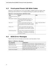
... . BIOS Error Messages Error Message Explanation CMOS Battery Low The battery may be bad. Replace the battery soon. CMOS memory may be losing power. If no VGA option ROM is powered off . Intel Desktop Board DX58OG Technical Product Specification 4.3 Front-panel Power LED Blink Codes Whenever a recoverable error occurs during POST, the BIOS causes the board's front panel power LED to blink an error message describing the problem (see Table 36). Memory Size Decreased Memory size has decreased since the last boot. Note When no memory was removed, then memory...
... . BIOS Error Messages Error Message Explanation CMOS Battery Low The battery may be bad. Replace the battery soon. CMOS memory may be losing power. If no VGA option ROM is powered off . Intel Desktop Board DX58OG Technical Product Specification 4.3 Front-panel Power LED Blink Codes Whenever a recoverable error occurs during POST, the BIOS causes the board's front panel power LED to blink an error message describing the problem (see Table 36). Memory Size Decreased Memory size has decreased since the last boot. Note When no memory was removed, then memory...
Product Specification
Page 73
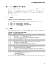
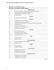
... and Beep Codes 4.5 Port 80h POST Codes During the POST, the BIOS generates diagnostic progress codes (POST codes) to I /O Busses: PCI, USB, ATA, etc. 5F is left at port 80h. AF B0 - See Table 39. FF E0 - Port 80h POST Code Ranges Range Category/Subsystem 00 - 0F Debug codes: Can be installed in PCI bus connector 1. This code is no memory detected or no useful memory detected. 30 - 3F 40 - 4F Recovery: 3F indicated recovery failure. NOTE The POST card...
... and Beep Codes 4.5 Port 80h POST Codes During the POST, the BIOS generates diagnostic progress codes (POST codes) to I /O Busses: PCI, USB, ATA, etc. 5F is left at port 80h. AF B0 - See Table 39. FF E0 - Port 80h POST Code Ranges Range Category/Subsystem 00 - 0F Debug codes: Can be installed in PCI bus connector 1. This code is no memory detected or no useful memory detected. 30 - 3F 40 - 4F Recovery: 3F indicated recovery failure. NOTE The POST card...
Product Specification
Page 74
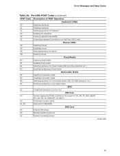
... Plug PCI controller initialization 53 - 57 Reserved for PCI Bus USB 58 Resetting USB bus 59 Reserved for USB ATA/ATAPI/SATA 5A Resetting PATA/SATA bus and all devices 5B Reserved for ATA SMBus 5C Resetting SMBus 5D Reserved for SMBus Local Console 70 Resetting the VGA controller 71 Disabling the VGA controller 72 Enabling the VGA controller Remote Console 78 Resetting the console controller 79 Disabling the console controller 7A Enabling the console controller continued 74 Intel Desktop Board DX58OG Technical Product Specification...
... Plug PCI controller initialization 53 - 57 Reserved for PCI Bus USB 58 Resetting USB bus 59 Reserved for USB ATA/ATAPI/SATA 5A Resetting PATA/SATA bus and all devices 5B Reserved for ATA SMBus 5C Resetting SMBus 5D Reserved for SMBus Local Console 70 Resetting the VGA controller 71 Disabling the VGA controller 72 Enabling the VGA controller Remote Console 78 Resetting the console controller 79 Disabling the console controller 7A Enabling the console controller continued 74 Intel Desktop Board DX58OG Technical Product Specification...
Product Specification
Page 75
... POST Operation Keyboard (USB) 90 Resetting keyboard 91 Disabling keyboard 92 Detecting presence of keyboard 93 Enabling the keyboard 94 Clearing keyboard input buffer 95 Instructing keyboard controller to run Self Test (PS/2 only) Mouse (USB) 98 Resetting mouse 99 Disabling mouse 9A Detecting presence of mouse 9B Enabling mouse Fixed Media B0 Resetting fixed media B1 Disabling fixed media B2 Detecting presence of a fixed media (IDE hard drive detection etc.) B3 Enabling/configuring a fixed media Removable...
... POST Operation Keyboard (USB) 90 Resetting keyboard 91 Disabling keyboard 92 Detecting presence of keyboard 93 Enabling the keyboard 94 Clearing keyboard input buffer 95 Instructing keyboard controller to run Self Test (PS/2 only) Mouse (USB) 98 Resetting mouse 99 Disabling mouse 9A Detecting presence of mouse 9B Enabling mouse Fixed Media B0 Resetting fixed media B1 Disabling fixed media B2 Detecting presence of a fixed media (IDE hard drive detection etc.) B3 Enabling/configuring a fixed media Removable...
Product Specification
Page 76
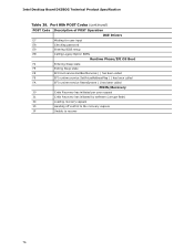
... password E9 Entering BIOS setup EB Calling Legacy Option ROMs Runtime Phase/EFI OS Boot F4 Entering Sleep state F5 Exiting Sleep state F8 EFI boot service ExitBootServices ( ) has been called F9 EFI runtime service SetVirtualAddressMap ( ) has been called FA EFI runtime service ResetSystem ( ) has been called PEIMs/Recovery 30 Crisis Recovery has initiated per user request 31 Crisis Recovery has initiated by software (corrupt flash) 34 Loading recovery capsule 35 Handing off control...
... password E9 Entering BIOS setup EB Calling Legacy Option ROMs Runtime Phase/EFI OS Boot F4 Entering Sleep state F5 Exiting Sleep state F8 EFI boot service ExitBootServices ( ) has been called F9 EFI runtime service SetVirtualAddressMap ( ) has been called FA EFI runtime service ResetSystem ( ) has been called PEIMs/Recovery 30 Crisis Recovery has initiated per user request 31 Crisis Recovery has initiated by software (corrupt flash) 34 Loading recovery capsule 35 Handing off control...
Product Specification
Page 77
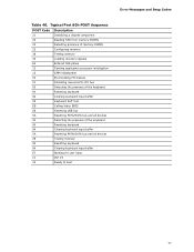
... POST Code Description 21 Initializing a chipset component 22 Reading SPD from memory DIMMs 23 Detecting presence of memory DIMMs 25 Configuring memory 28 Testing memory 34 Loading recovery capsule E4 Entered DXE phase 12 Starting application processor initialization 13 SMM initialization 50 Enumerating PCI busses 51 Allocating resourced to PCI bus 92 Detecting the presence of the keyboard 90 Resetting keyboard 94 Clearing keyboard input buffer 95 Keyboard Self Test EB Calling Video BIOS...
... POST Code Description 21 Initializing a chipset component 22 Reading SPD from memory DIMMs 23 Detecting presence of memory DIMMs 25 Configuring memory 28 Testing memory 34 Loading recovery capsule E4 Entered DXE phase 12 Starting application processor initialization 13 SMM initialization 50 Enumerating PCI busses 51 Allocating resourced to PCI bus 92 Detecting the presence of the keyboard 90 Resetting keyboard 94 Clearing keyboard input buffer 95 Keyboard Self Test EB Calling Video BIOS...


