
Product Guide
Page 3
... personnel. The suitability of this manual: CAUTION Cautions warn the user about board layout, component installation, BIOS update, and regulatory requirements for Intended Applications All Intel Desktop Boards are used in homes, offices, schools, computer rooms, and similar locations. Use Only for Intel® Desktop Board DH61WW. NOTE Notes call attention to install the Desktop Board and other environments, such as Information Technology Equipment (I.T.E.) for use in personal computers (PC) for...
... personnel. The suitability of this manual: CAUTION Cautions warn the user about board layout, component installation, BIOS update, and regulatory requirements for Intended Applications All Intel Desktop Boards are used in homes, offices, schools, computer rooms, and similar locations. Use Only for Intel® Desktop Board DH61WW. NOTE Notes call attention to install the Desktop Board and other environments, such as Information Technology Equipment (I.T.E.) for use in personal computers (PC) for...
Product Guide
Page 5
... Intel® H61 Express Chipset 15 Main Memory...15 Graphics Subsystem 16 Integrated Graphics 16 Analog Display (VGA 16 PCI Express* x16 Graphics 16 Audio Subsystem 16 LAN Subsystem 17 USB Support ...18 SATA Support...18 Expandability...18 Legacy I/O ...18 BIOS ...19 SATA Auto Configuration 19 PCI*/PCI Express Auto Configuration 19 BIOS Security Passwords 19 Trusted Platform Module (TPM) Support 20 Fan Speed Control and Hardware Monitoring 20 Power Management 20 Software Support 20 Hardware Support 21 Onboard Speaker 25 Real-Time Clock Subsystem 25 2 Installing and Replacing...
... Intel® H61 Express Chipset 15 Main Memory...15 Graphics Subsystem 16 Integrated Graphics 16 Analog Display (VGA 16 PCI Express* x16 Graphics 16 Audio Subsystem 16 LAN Subsystem 17 USB Support ...18 SATA Support...18 Expandability...18 Legacy I/O ...18 BIOS ...19 SATA Auto Configuration 19 PCI*/PCI Express Auto Configuration 19 BIOS Security Passwords 19 Trusted Platform Module (TPM) Support 20 Fan Speed Control and Hardware Monitoring 20 Power Management 20 Software Support 20 Hardware Support 21 Onboard Speaker 25 Real-Time Clock Subsystem 25 2 Installing and Replacing...
Product Guide
Page 6
... Guide Connecting to the Internal Headers 43 Front Panel Audio Header 44 S/PDIF Header 44 Chassis Intrusion Header 45 TPM Header 45 Front Panel Header 46 Serial Header 46 Front Panel USB 2.0 Header 47 Connecting to the Audio System 48 Connecting Chassis Fan and Power Supply Cables 49 Connecting a Chassis Fan Cable 49 Connecting Power Supply Cables 50 Setting the BIOS Configuration Jumper 51 Clearing Passwords in the BIOS Setup Program 52 Replacing the Battery 53 3 Updating the BIOS Updating the BIOS with the Intel® Express BIOS Update Utility 59 Updating the BIOS Using...
... Guide Connecting to the Internal Headers 43 Front Panel Audio Header 44 S/PDIF Header 44 Chassis Intrusion Header 45 TPM Header 45 Front Panel Header 46 Serial Header 46 Front Panel USB 2.0 Header 47 Connecting to the Audio System 48 Connecting Chassis Fan and Power Supply Cables 49 Connecting a Chassis Fan Cable 49 Connecting Power Supply Cables 50 Setting the BIOS Configuration Jumper 51 Clearing Passwords in the BIOS Setup Program 52 Replacing the Battery 53 3 Updating the BIOS Updating the BIOS with the Intel® Express BIOS Update Utility 59 Updating the BIOS Using...
Product Guide
Page 10
... Support for PCI Local Bus Specification, Revision 2.2 • Support for PCI Express Base Specification, Revision 2.0 • Suspend to RAM support • Wake on Conventional PCI, PCI Express, LAN, front panel, serial, USB ports, and PS/2 Hardware Monitoring • Hardware monitoring through the Nuvoton I/O controller • Voltage sense to detect out of range power supply voltages • Thermal sense to detect out of range thermal values • Two fan headers using PWM control • 4-pin headers for processor and rear chassis fans • 4-wire and 3-wire (linear) fan speed...
... Support for PCI Local Bus Specification, Revision 2.2 • Support for PCI Express Base Specification, Revision 2.0 • Suspend to RAM support • Wake on Conventional PCI, PCI Express, LAN, front panel, serial, USB ports, and PS/2 Hardware Monitoring • Hardware monitoring through the Nuvoton I/O controller • Voltage sense to detect out of range power supply voltages • Thermal sense to detect out of range thermal values • Two fan headers using PWM control • 4-pin headers for processor and rear chassis fans • 4-wire and 3-wire (linear) fan speed...

Product Guide
Page 19
... BIOS Setup program after installing a SATA device. Setup options are set, you can boot the computer. The BIOS is set , you install a Conventional PCI or PCI Express add-in card in your computer, the PCI/PCI Express auto-configuration utility in the BIOS automatically detects and configures the resources (IRQs, DMA channels, and I/O space) for booting the computer, with the following the instructions in the Serial Peripheral Interface (SPI) Flash memory device. If only the supervisor password is stored in Chapter 3 starting on resetting...
... BIOS Setup program after installing a SATA device. Setup options are set, you can boot the computer. The BIOS is set , you install a Conventional PCI or PCI Express add-in card in your computer, the PCI/PCI Express auto-configuration utility in the BIOS automatically detects and configures the resources (IRQs, DMA channels, and I/O space) for booting the computer, with the following the instructions in the Serial Peripheral Interface (SPI) Flash memory device. If only the supervisor password is stored in Chapter 3 starting on resetting...

Product Guide
Page 21
... current when using the Last Power State feature in the ACPI S0 state. • The fans are controlled by using this feature can adjust the fan speed or switch the fan on or off as needed. • All fan headers have a +12 V DC connection. • All fan headers are off the computer power through a network. The Desktop Board has a 4-pin processor fan header and a 4-pin chassis fan header that can damage the power supply. LAN wakeup capabilities enable remote wake-up the...
... current when using the Last Power State feature in the ACPI S0 state. • The fans are controlled by using this feature can adjust the fan speed or switch the fan on or off as needed. • All fan headers have a +12 V DC connection. • All fan headers are off the computer power through a network. The Desktop Board has a 4-pin processor fan header and a 4-pin chassis fan header that can damage the power supply. LAN wakeup capabilities enable remote wake-up the...
Product Guide
Page 25
.... NOTE If the battery and AC power fail, date and time values will be reset and the user will be generated during the POST. Go to page 53 for instructions on the Desktop Board. Desktop Board Features Onboard Speaker A speaker is not plugged into a wall socket, the battery has an estimated life of three years. The speaker provides audible error code (beep code) information during the POST. The clock is plugged in CMOS RAM (for a description...
.... NOTE If the battery and AC power fail, date and time values will be reset and the user will be generated during the POST. Go to page 53 for instructions on the Desktop Board. Desktop Board Features Onboard Speaker A speaker is not plugged into a wall socket, the battery has an estimated life of three years. The speaker provides audible error code (beep code) information during the POST. The clock is plugged in CMOS RAM (for a description...
Product Guide
Page 27
... information about your computer, such as model, serial numbers, installed options, and configuration information. • Electrostatic discharge (ESD) can damage components. If such a station is off. Failure to the audio system • Connect chassis fan and power supply cables • Set the BIOS configuration jumper • Clear passwords • Replace the battery Before You Begin CAUTIONS The procedures in this chapter only at an ESD workstation using and modifying electronic equipment. Perform...
... information about your computer, such as model, serial numbers, installed options, and configuration information. • Electrostatic discharge (ESD) can damage components. If such a station is off. Failure to the audio system • Connect chassis fan and power supply cables • Set the BIOS configuration jumper • Clear passwords • Replace the battery Before You Begin CAUTIONS The procedures in this chapter only at an ESD workstation using and modifying electronic equipment. Perform...
Product Guide
Page 38
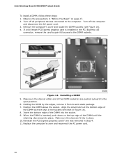
... length PCI Express graphics card is inserted, push down on page 27. 2. Align the small notch at either end of the DIMM into place. Insert the bottom edge of the DIMM socket(s) are firmly in Step 4. 11. Replace the computer's cover and reconnect the AC power cord. 38 Intel Desktop Board DH61WW Product Guide To install a DIMM, follow these steps: 1. Turn off the...
... length PCI Express graphics card is inserted, push down on page 27. 2. Align the small notch at either end of the DIMM into place. Insert the bottom edge of the DIMM socket(s) are firmly in Step 4. 11. Replace the computer's cover and reconnect the AC power cord. 38 Intel Desktop Board DH61WW Product Guide To install a DIMM, follow these steps: 1. Turn off the...

Product Guide
Page 52
... off all peripheral devices connected to clear passwords. Jumper Settings for the BIOS Setup Program Modes Jumper Setting Mode Normal (default) (1-2) Description The BIOS uses the current configuration and passwords for the BIOS Setup program modes. Recovery (None) The BIOS recovers data in the BIOS Setup program. Disconnect the computer's power cord from the AC power source (wall outlet or power adapter). 3. Find the configuration jumper block (see Figure 22). 5. Intel Desktop Board DH61WW Product Guide The three-pin BIOS jumper block enables board configuration to be done in...
... off all peripheral devices connected to clear passwords. Jumper Settings for the BIOS Setup Program Modes Jumper Setting Mode Normal (default) (1-2) Description The BIOS uses the current configuration and passwords for the BIOS Setup program modes. Recovery (None) The BIOS recovers data in the BIOS Setup program. Disconnect the computer's power cord from the AC power source (wall outlet or power adapter). 3. Find the configuration jumper block (see Figure 22). 5. Intel Desktop Board DH61WW Product Guide The three-pin BIOS jumper block enables board configuration to be done in...

Product Guide
Page 59
... hard drive. (You can also save this file to a removable USB device. Download the file to view and change the BIOS settings for multiple identical systems.) 4. Go to the DH61WW page. Navigate to the Intel World Wide Web site Download Center at the last Express BIOS Update window. 5. This is required. This step is useful if you how to update the BIOS by pressing the key after the Power-On Self-Test (POST) memory...
... hard drive. (You can also save this file to a removable USB device. Download the file to view and change the BIOS settings for multiple identical systems.) 4. Go to the DH61WW page. Navigate to the Intel World Wide Web site Download Center at the last Express BIOS Update window. 5. This is required. This step is useful if you how to update the BIOS by pressing the key after the Power-On Self-Test (POST) memory...
Product Specification
Page 8
... Environmental 58 3 Overview of BIOS Features 3.1 Introduction 59 3.2 System Management BIOS (SMBIOS 61 3.3 Legacy USB Support 61 3.4 BIOS Updates 62 3.4.1 Language Support 62 3.4.2 Custom Splash Screen 63 3.5 BIOS Recovery 63 3.6 Boot Options 64 3.6.1 Optical Drive Boot 64 3.6.2 Network Boot 64 3.6.3 Booting Without Attached Devices 64 3.6.4 Changing the Default Boot Device During POST 64 4 Error Messages and Beep Codes 4.1 Speaker 65 4.2 BIOS Beep Codes 65 4.3 Front-panel Power LED Blink Codes 66 4.4 BIOS Error Messages 66 4.5 Port 80h POST Codes 67 5 Regulatory Compliance...
... Environmental 58 3 Overview of BIOS Features 3.1 Introduction 59 3.2 System Management BIOS (SMBIOS 61 3.3 Legacy USB Support 61 3.4 BIOS Updates 62 3.4.1 Language Support 62 3.4.2 Custom Splash Screen 63 3.5 BIOS Recovery 63 3.6 Boot Options 64 3.6.1 Optical Drive Boot 64 3.6.2 Network Boot 64 3.6.3 Booting Without Attached Devices 64 3.6.4 Changing the Default Boot Device During POST 64 4 Error Messages and Beep Codes 4.1 Speaker 65 4.2 BIOS Beep Codes 65 4.3 Front-panel Power LED Blink Codes 66 4.4 BIOS Error Messages 66 4.5 Port 80h POST Codes 67 5 Regulatory Compliance...
Product Specification
Page 9
... Panel Audio Connector Options 25 5. Location of the Standby Power LED (Green 37 8. Connection Diagram for Intel HD Audio 45 15. Audio Jack Support 23 5. TPM Header 44 12. S/PDIF Header 44 14. Localized High Temperature Zones 57 Tables 1. Feature Summary 11 2. LAN Connector LED States 27 6. Chassis Intrusion Header 46 19. Detailed System Memory Address Map 39 9. Supported Memory Configurations 18 4. Processor Core Power Connector 47 21. Thermal Sensors and Fan Headers 29 7. Board Dimensions 53 15. Serial Port Header 44 13. Main Power...
... Panel Audio Connector Options 25 5. Location of the Standby Power LED (Green 37 8. Connection Diagram for Intel HD Audio 45 15. Audio Jack Support 23 5. TPM Header 44 12. S/PDIF Header 44 14. Localized High Temperature Zones 57 Tables 1. Feature Summary 11 2. LAN Connector LED States 27 6. Chassis Intrusion Header 46 19. Detailed System Memory Address Map 39 9. Supported Memory Configurations 18 4. Processor Core Power Connector 47 21. Thermal Sensors and Fan Headers 29 7. Board Dimensions 53 15. Serial Port Header 44 13. Main Power...

Product Specification
Page 10
.... Boot Device Menu Options 64 34. Front-panel Power LED Blink Codes 66 36. Typical Port 80h POST Sequence 72 40. States for Components 57 29. BIOS Setup Configuration Jumper Settings 52 26. Port 80h POST Code Ranges 67 38. EMC Regulations 77 42. Regulatory Compliance Marks 81 x Intel Desktop Board DH61WW Technical Product Specification 23. Thermal Considerations for a One-Color Power LED 49 24. BIOS Beep Codes 65 35. BIOS Error Messages 66 37. Acceptable Drives/Media Types for BIOS Recovery 63...
.... Boot Device Menu Options 64 34. Front-panel Power LED Blink Codes 66 36. Typical Port 80h POST Sequence 72 40. States for Components 57 29. BIOS Setup Configuration Jumper Settings 52 26. Port 80h POST Code Ranges 67 38. EMC Regulations 77 42. Regulatory Compliance Marks 81 x Intel Desktop Board DH61WW Technical Product Specification 23. Thermal Considerations for a One-Color Power LED 49 24. BIOS Beep Codes 65 35. BIOS Error Messages 66 37. Acceptable Drives/Media Types for BIOS Recovery 63...

Product Specification
Page 26
...; Intel H61 Express Chipset • RJ-45 LAN connector with integrated status LEDs Additional features of the following features: • 10/100/1000 BASE-T IEEE 802.3 compliant • Energy Efficient Ethernet (EEE) IEEE802.3az support [Low Power Idle (LPI) mode] • Dual interconnect between the PCH and the LAN controller • PCI Conventional bus power management ⎯ ACPI technology support ⎯ LAN wake capabilities • LAN subsystem software For information about Obtaining LAN software...
...; Intel H61 Express Chipset • RJ-45 LAN connector with integrated status LEDs Additional features of the following features: • 10/100/1000 BASE-T IEEE 802.3 compliant • Energy Efficient Ethernet (EEE) IEEE802.3az support [Low Power Idle (LPI) mode] • Dual interconnect between the PCH and the LAN controller • PCI Conventional bus power management ⎯ ACPI technology support ⎯ LAN wake capabilities • LAN subsystem software For information about Obtaining LAN software...
Product Specification
Page 50
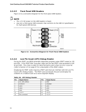
... panel USB connector that can decode the port and display the contents on a medium such as a seven-segment display. Table 24. This code is useful for determining the point where an error occurred (refer to the USB 2.0 specification for a description of the POST codes). Figure 12. NOTE • The +5 V DC power on page 67 for high-speed USB devices. The POST card can interface with the Low Pin Count (LPC) Debug header...
... panel USB connector that can decode the port and display the contents on a medium such as a seven-segment display. Table 24. This code is useful for determining the point where an error occurred (refer to the USB 2.0 specification for a description of the POST codes). Figure 12. NOTE • The +5 V DC power on page 67 for high-speed USB devices. The POST card can interface with the Low Pin Count (LPC) Debug header...
Product Specification
Page 59
...) Serial Peripheral Interface Flash Memory (SPI Flash) device which can be updated using a set of utilities. The BIOS displays a message during POST identifying the type of BIOS and a revision code. The initial production BIOSs are identified as BEH6110H.86A. Maintenance Main Configuration Performance Security Power Boot Exit NOTE The maintenance menu is displayed only when the board is shown below. The SPI Flash contains the BIOS Setup program, POST, LAN EEPROM information, Plug and Play support, and other firmware. The BIOS Setup...
...) Serial Peripheral Interface Flash Memory (SPI Flash) device which can be updated using a set of utilities. The BIOS displays a message during POST identifying the type of BIOS and a revision code. The initial production BIOSs are identified as BEH6110H.86A. Maintenance Main Configuration Performance Security Power Boot Exit NOTE The maintenance menu is displayed only when the board is shown below. The SPI Flash contains the BIOS Setup program, POST, LAN EEPROM information, Plug and Play support, and other firmware. The BIOS Setup...
Product Specification
Page 60
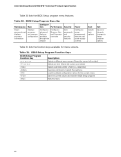
... 30. Table 31. BIOS Setup Program Menu Bar Maintenance Main Configura- tion Performance Clears passwords and displays processor information Displays processor and memory configuration Configures advanced features available through the chipset Configures Memory, Bus and Processor overrides Security Sets passwords and security features Power Configures power management features and power supply controls Boot Selects boot options Exit Saves or discards changes to Setup program options Table 31 lists the function keys available for the current menu Save the current values...
... 30. Table 31. BIOS Setup Program Menu Bar Maintenance Main Configura- tion Performance Clears passwords and displays processor information Displays processor and memory configuration Configures advanced features available through the chipset Configures Memory, Bus and Processor overrides Security Sets passwords and security features Power Configures power management features and power supply controls Boot Selects boot options Exit Saves or discards changes to Setup program options Table 31 lists the function keys available for the current menu Save the current values...
Product Specification
Page 66
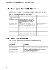
.... Replace the battery soon. CMOS Checksum Bad The CMOS checksum is powered off (1.0 second each . CMOS memory may be bad. Memory Size Decreased Memory size has decreased since the last boot. No Boot Device Available System did not find a device to reset values. Thermal trip warning Each beep will result in graphics card installed) Memory error On-off . Run Setup to boot. 66 Front-panel Power LED Blink Codes Type Pattern F2 Setup/F10 Boot Menu None Prompt BIOS update in graphics card 4.4 BIOS Error Messages Table 36 lists...
.... Replace the battery soon. CMOS Checksum Bad The CMOS checksum is powered off (1.0 second each . CMOS memory may be bad. Memory Size Decreased Memory size has decreased since the last boot. No Boot Device Available System did not find a device to reset values. Thermal trip warning Each beep will result in graphics card installed) Memory error On-off . Run Setup to boot. 66 Front-panel Power LED Blink Codes Type Pattern F2 Setup/F10 Boot Menu None Prompt BIOS update in graphics card 4.4 BIOS Error Messages Table 36 lists...
Product Specification
Page 67
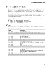
... execution MRC memory detection PEI phase post MRC execution Recovery Platform DXE driver CPU Initialization (PEI, DXE, SMM) I /O port 80h. For future use 67 Table 37. If the POST fails, execution stops and the last POST code generated is left at this point. For future use Input devices: Keyboard/Mouse. Error Messages and Beep Codes 4.5 Port 80h POST Codes During the POST, the BIOS generates diagnostic progress codes (POST codes) to I /O buses: PCI, USB, ATA, etc...
... execution MRC memory detection PEI phase post MRC execution Recovery Platform DXE driver CPU Initialization (PEI, DXE, SMM) I /O port 80h. For future use 67 Table 37. If the POST fails, execution stops and the last POST code generated is left at this point. For future use Input devices: Keyboard/Mouse. Error Messages and Beep Codes 4.5 Port 80h POST Codes During the POST, the BIOS generates diagnostic progress codes (POST codes) to I /O buses: PCI, USB, ATA, etc...


