Product Specification
Page 5
... IDE Support 24 1.5.4 Real-Time Clock, CMOS SRAM, and Battery 25 1.6 PCI Express* Connectors 25 1.7 Legacy I/O Controller 26 1.7.1 Serial Port 26 1.7.2 Parallel Port 26 1.7.3 Diskette Drive Controller 26 1.7.4 Keyboard and Mouse Interface 26 1.8 Audio Subsystem 27 1.8.1 Audio Subsystem Software 27 1.8.2 Audio Connectors 27 1.8.3 6-Channel (5.1) Audio Subsystem 28 1.9 LAN Subsystem 29 1.9.1 LAN Subsystem Software 29 1.9.2 Intel® 82562G Physical Layer Interface Device 29 1.10 Hardware Management Subsystem 31 1.10.1 Hardware Monitoring and Fan Control ASIC 31 1.10.2 Chassis...
... IDE Support 24 1.5.4 Real-Time Clock, CMOS SRAM, and Battery 25 1.6 PCI Express* Connectors 25 1.7 Legacy I/O Controller 26 1.7.1 Serial Port 26 1.7.2 Parallel Port 26 1.7.3 Diskette Drive Controller 26 1.7.4 Keyboard and Mouse Interface 26 1.8 Audio Subsystem 27 1.8.1 Audio Subsystem Software 27 1.8.2 Audio Connectors 27 1.8.3 6-Channel (5.1) Audio Subsystem 28 1.9 LAN Subsystem 29 1.9.1 LAN Subsystem Software 29 1.9.2 Intel® 82562G Physical Layer Interface Device 29 1.10 Hardware Management Subsystem 31 1.10.1 Hardware Monitoring and Fan Control ASIC 31 1.10.2 Chassis...
Product Specification
Page 6
... PCI IDE Support 71 3.4 System Management BIOS (SMBIOS 71 3.5 BIOS Updates 72 3.5.1 Language Support 72 3.5.2 Custom Splash Screen 72 3.6 Legacy USB Support 73 3.7 Boot Options 73 3.7.1 CD-ROM Boot 73 3.7.2 Network Boot 73 3.7.3 Booting Without Attached Devices 74 3.7.4 Changing the Default Boot Device During POST 74 3.8 Adjusting Boot Speed 75 3.8.1 Peripheral Selection and Configuration 75 3.8.2 BIOS Boot Optimizations 75 3.9 BIOS Security Features 76 4 Error Messages and Beep Codes 4.1 Speaker 77 4.2 BIOS Beep Codes 77 4.3 BIOS Error Messages 77 4.4 Port 80h POST Codes...
... PCI IDE Support 71 3.4 System Management BIOS (SMBIOS 71 3.5 BIOS Updates 72 3.5.1 Language Support 72 3.5.2 Custom Splash Screen 72 3.6 Legacy USB Support 73 3.7 Boot Options 73 3.7.1 CD-ROM Boot 73 3.7.2 Network Boot 73 3.7.3 Booting Without Attached Devices 74 3.7.4 Changing the Default Boot Device During POST 74 3.8 Adjusting Boot Speed 75 3.8.1 Peripheral Selection and Configuration 75 3.8.2 BIOS Boot Optimizations 75 3.9 BIOS Security Features 76 4 Error Messages and Beep Codes 4.1 Speaker 77 4.2 BIOS Beep Codes 77 4.3 BIOS Error Messages 77 4.4 Port 80h POST Codes...
Product Specification
Page 7
... Panel Audio Connector Options 28 8. Component-side Connectors and Headers 50 14. Memory Operating Frequencies 17 5. DMA Channels 43 11. Dual Channel (Interleaved) Mode Configuration with Two DIMMs 19 5. LAN Connector LED Locations 30 9. PCI Interrupt Routing Map 47 vii Board Components Shown in Figure 1 13 3. Block Diagram 14 3. Detailed System Memory Address Map 42 12. Connection Diagram for Front Panel Header 55 15. Localized High Temperature Zones 65 Tables 1. I /O Shield Dimensions 61 19. Supported Memory Configurations 16 4. Wake-up Devices...
... Panel Audio Connector Options 28 8. Component-side Connectors and Headers 50 14. Memory Operating Frequencies 17 5. DMA Channels 43 11. Dual Channel (Interleaved) Mode Configuration with Two DIMMs 19 5. LAN Connector LED Locations 30 9. PCI Interrupt Routing Map 47 vii Board Components Shown in Figure 1 13 3. Block Diagram 14 3. Detailed System Memory Address Map 42 12. Connection Diagram for Front Panel Header 55 15. Localized High Temperature Zones 65 Tables 1. I /O Shield Dimensions 61 19. Supported Memory Configurations 16 4. Wake-up Devices...
Product Specification
Page 8
.... Port 80h POST Codes 79 40. Processor Fan Header 52 20. DC Loading Characteristics 62 29. Lead-Free Board Markings 88 43. Product Certification Markings 90 viii BIOS Setup Configuration Jumper Settings 59 28. Fan Header Current Capability 63 30. BIOS Setup Program Function Keys 70 34. Boot Device Menu Options 74 35. BIOS Error Messages 77 38. States for a One-Color Power LED 56 26. BIOS Setup Program Menu Bar 70 33. Chassis Intrusion Header 52 18. Serial ATA Connectors 52 19. Processor Core Power Connector 53...
.... Port 80h POST Codes 79 40. Processor Fan Header 52 20. DC Loading Characteristics 62 29. Lead-Free Board Markings 88 43. Product Certification Markings 90 viii BIOS Setup Configuration Jumper Settings 59 28. Fan Header Current Capability 63 30. BIOS Setup Program Function Keys 70 34. Boot Device Menu Options 74 35. BIOS Error Messages 77 38. States for a One-Color Power LED 56 26. BIOS Setup Program Menu Bar 70 33. Chassis Intrusion Header 52 18. Serial ATA Connectors 52 19. Processor Core Power Connector 53...
Product Specification
Page 10
... Factor Processor Memory Chipset Video Audio Legacy I /O controller for diskette drive, serial, parallel, and PS/2* ports Support for USB 2.0 devices • Eight USB ports • One serial port • One parallel port • Four Serial ATA interfaces • One Parallel ATA IDE interface with UDMA 33, ATA-66/100 support • One diskette drive interface • PS/2 keyboard and mouse ports 10/100 Mbits/sec LAN subsystem using the Intel® 82562G Platform LAN Connect (PLC) device • Intel® BIOS (resident...
... Factor Processor Memory Chipset Video Audio Legacy I /O controller for diskette drive, serial, parallel, and PS/2* ports Support for USB 2.0 devices • Eight USB ports • One serial port • One parallel port • Four Serial ATA interfaces • One Parallel ATA IDE interface with UDMA 33, ATA-66/100 support • One diskette drive interface • PS/2 keyboard and mouse ports 10/100 Mbits/sec LAN subsystem using the Intel® 82562G Platform LAN Connect (PLC) device • Intel® BIOS (resident...
Product Specification
Page 16
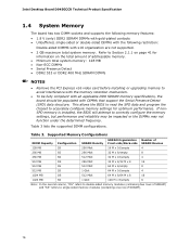
... memory specifications, the board should be impacted or the DIMMs may not function under the determined frequency. This allows the BIOS to read the SPD data and program the chipset to correctly configure the memory settings, but performance and reliability may be populated with DIMMs that support the Serial Presence Detect (SPD) data structure. Table 3 lists the supported DIMM configurations. If nonSPD memory is installed, the BIOS...
... memory specifications, the board should be impacted or the DIMMs may not function under the determined frequency. This allows the BIOS to read the SPD data and program the chipset to correctly configure the memory settings, but performance and reliability may be populated with DIMMs that support the Serial Presence Detect (SPD) data structure. Table 3 lists the supported DIMM configurations. If nonSPD memory is installed, the BIOS...

Product Specification
Page 21
When a PCI Express x16 add-in card can be used by the chipset Refer to the CPU, memory, PCI Express, and the DMI interconnect. The ICH7 is used, or a PCI Express x16 add-in card is installed, the GMA950 graphics controller is disabled. 1.5.1.1 Intel® GMA950 Graphics Controller The Intel GMA950 graphics controller features the following: • 400 MHz core frequency • High performance 3-D setup and render engine • High quality texture engine ⎯ DX9* Compliant Hardware Pixel Shader...
When a PCI Express x16 add-in card can be used by the chipset Refer to the CPU, memory, PCI Express, and the DMI interconnect. The ICH7 is used, or a PCI Express x16 add-in card is installed, the GMA950 graphics controller is disabled. 1.5.1.1 Intel® GMA950 Graphics Controller The Intel GMA950 graphics controller features the following: • 400 MHz core frequency • High performance 3-D setup and render engine • High quality texture engine ⎯ DX9* Compliant Hardware Pixel Shader...

Product Specification
Page 22
...-in the BIOS Setup program) for compatibility with 200 MHz pixel clocks using VGA graphics under DOS. NOTE The use of DVMT requires operating system driver support. 22 DVMT ensures the most efficient use of available system memory for maximum 2-D/3-D graphics performance. Intel Desktop Board D945GCCR Technical Product Specification • Video ⎯ Hardware motion compensation for MPEG2 ⎯ Software DVD at 30 fps full screen • Display ⎯ Integrated 24-bit 400 MHz...
...-in the BIOS Setup program) for compatibility with 200 MHz pixel clocks using VGA graphics under DOS. NOTE The use of DVMT requires operating system driver support. 22 DVMT ensures the most efficient use of available system memory for maximum 2-D/3-D graphics performance. Intel Desktop Board D945GCCR Technical Product Specification • Video ⎯ Hardware motion compensation for MPEG2 ⎯ Software DVD at 30 fps full screen • Display ⎯ Integrated 24-bit 400 MHz...
Product Specification
Page 29
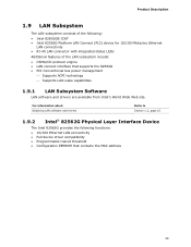
...Intel 82801GB ICH7 • Intel 82562G Platform LAN Connect (PLC) device for 10/100 Mbits/sec Ethernet LAN connectivity • RJ-45 LAN connector with integrated status LEDs Additional features of the following functions: • 10/100 Ethernet LAN connectivity • Full device driver compatibility • Programmable transit threshold • Configuration EEPROM that supports the 82562G • PCI Conventional bus power management ⎯ Supports ACPI technology ⎯ Supports LAN wake capabilities 1.9.1 LAN Subsystem Software LAN software and drivers are available from Intel...
...Intel 82801GB ICH7 • Intel 82562G Platform LAN Connect (PLC) device for 10/100 Mbits/sec Ethernet LAN connectivity • RJ-45 LAN connector with integrated status LEDs Additional features of the following functions: • 10/100 Ethernet LAN connectivity • Full device driver compatibility • Programmable transit threshold • Configuration EEPROM that supports the 82562G • PCI Conventional bus power management ⎯ Supports ACPI technology ⎯ Supports LAN wake capabilities 1.9.1 LAN Subsystem Software LAN software and drivers are available from Intel...

Product Specification
Page 35
... panel Serial Port A) PME# signal S1, S3 S1, S3, S4, S5 (Note) Power switch S1, S3, S4, S5 PS/2 devices S1, S3 RTC alarm S1, S3, S4, S5 USB S1, S3 WAKE# signal S1, S3, S4, S5 Note: For LAN and PME# signal, S5 is disabled by default in the S5 state. The board provides several power management hardware features, including: • Power connector • Fan headers...
... panel Serial Port A) PME# signal S1, S3 S1, S3, S4, S5 (Note) Power switch S1, S3, S4, S5 PS/2 devices S1, S3 RTC alarm S1, S3, S4, S5 USB S1, S3 WAKE# signal S1, S3, S4, S5 Note: For LAN and PME# signal, S5 is disabled by default in the S5 state. The board provides several power management hardware features, including: • Power connector • Fan headers...
Product Specification
Page 36
... enables telephony devices to a fan tachometer input of telephony device (external or internal). When an ACPI-enabled system receives the correct command, the power supply removes all non-standby voltages. Intel Desktop Board D945GCCR Technical Product Specification Resume on or off). The method used depends on the type of the hardware monitoring and fan control ASIC. • All fan headers support closed-loop fan control that provides full ACPI support. 1.11.2.1 Power Connector ATX12V-compliant power supplies can turn off the system power...
... enables telephony devices to a fan tachometer input of telephony device (external or internal). When an ACPI-enabled system receives the correct command, the power supply removes all non-standby voltages. Intel Desktop Board D945GCCR Technical Product Specification Resume on or off). The method used depends on the type of the hardware monitoring and fan control ASIC. • All fan headers support closed-loop fan control that provides full ACPI support. 1.11.2.1 Power Connector ATX12V-compliant power supplies can turn off the system power...
Product Specification
Page 45
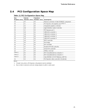
... 02 Serial ATA controller 00 1F 03 SMBus controller (Note 2) 00 00 PCI Conventional bus connector 1 (Note 2) 01 00 PCI Conventional bus connector 2 (Note 2) 08 00 Intel 82562G 10/100 Mbits/sec LAN PLC 01 00 00 PCI Express video controller (if present) Notes: 1. Technical Reference 2.4 PCI Configuration Space Map Table 12. Present only when a PCI Express x16 graphics card is dynamic and can change based on add-in cards used. 45 Bus number is installed. 2.
... 02 Serial ATA controller 00 1F 03 SMBus controller (Note 2) 00 00 PCI Conventional bus connector 1 (Note 2) 01 00 PCI Conventional bus connector 2 (Note 2) 08 00 Intel 82562G 10/100 Mbits/sec LAN PLC 01 00 00 PCI Express video controller (if present) Notes: 1. Technical Reference 2.4 PCI Configuration Space Map Table 12. Present only when a PCI Express x16 graphics card is dynamic and can change based on add-in cards used. 45 Bus number is installed. 2.
Product Specification
Page 48
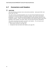
...'s chassis, such as fans and internal peripherals. Intel Desktop Board D945GCCR Technical Product Specification 2.7 Connectors and Headers CAUTION Only the following connectors have overcurrent protection: back panel USB, front panel USB, and PS/2. Do not use these groups: • Back panel connectors (see page 49) • Component-side connectors and headers (see page 50) 48 This section describes the board's connectors and headers. The connectors and headers can be divided into these connectors/headers to power devices external...
...'s chassis, such as fans and internal peripherals. Intel Desktop Board D945GCCR Technical Product Specification 2.7 Connectors and Headers CAUTION Only the following connectors have overcurrent protection: back panel USB, front panel USB, and PS/2. Do not use these groups: • Back panel connectors (see page 49) • Component-side connectors and headers (see page 50) 48 This section describes the board's connectors and headers. The connectors and headers can be divided into these connectors/headers to power devices external...

Product Specification
Page 69
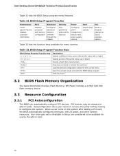
... 3.6 Legacy USB Support 73 3.7 Boot Options 73 3.8 Adjusting Boot Speed 75 3.9 BIOS Security Features 76 3.1 Introduction The boards use an Intel BIOS that is stored in the Serial Peripheral Interface Flash Memory (SPI Flash) and can be updated using a disk-based program. The BIOS Setup program is shown below. Maintenance Main Advanced Security Power Boot Exit NOTE The maintenance menu is displayed only when the Desktop Board is powered-up, the BIOS compares the CPU version and the microcode version in configure mode. When the BIOS Setup configuration jumper...
... 3.6 Legacy USB Support 73 3.7 Boot Options 73 3.8 Adjusting Boot Speed 75 3.9 BIOS Security Features 76 3.1 Introduction The boards use an Intel BIOS that is stored in the Serial Peripheral Interface Flash Memory (SPI Flash) and can be updated using a disk-based program. The BIOS Setup program is shown below. Maintenance Main Advanced Security Power Boot Exit NOTE The maintenance menu is displayed only when the Desktop Board is powered-up, the BIOS compares the CPU version and the microcode version in configure mode. When the BIOS Setup configuration jumper...
Product Specification
Page 70
... considered to be onboard or add-in card. 70 BIOS Setup Program Menu Bar Maintenance Clears passwords and displays processor information Main Advanced Displays processor and memory configuration Configures advanced features available through the chipset Security Sets passwords and security features Power Boot Configures power management features and power supply controls Selects boot options Exit Saves or discards changes to configure the system. PCI devices may be available for use by the add-in cards. Table 33. Table 32. Intel Desktop Board D945GCCR Technical...
... considered to be onboard or add-in card. 70 BIOS Setup Program Menu Bar Maintenance Clears passwords and displays processor information Main Advanced Displays processor and memory configuration Configures advanced features available through the chipset Security Sets passwords and security features Power Boot Configures power management features and power supply controls Selects boot options Exit Saves or discards changes to configure the system. PCI devices may be available for use by the add-in cards. Table 33. Table 32. Intel Desktop Board D945GCCR Technical...
Product Specification
Page 71
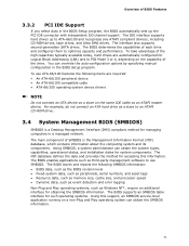
... method for accessing this support, an SMBIOS service-level application running on the same IDE cable as Windows NT*, require an additional interface for such operating systems. Using this information. Using SMBIOS, a system administrator can override the auto-configuration options by specifying manual configuration in a managed network. The BIOS supports an SMBIOS table interface for obtaining the SMBIOS information. The IDE interface supports hard drives up the PCI IDE connector with independent I/O channel support. To...
... method for accessing this support, an SMBIOS service-level application running on the same IDE cable as Windows NT*, require an additional interface for such operating systems. Using this information. Using SMBIOS, a system administrator can override the auto-configuration options by specifying manual configuration in a managed network. The BIOS supports an SMBIOS table interface for obtaining the SMBIOS information. The IDE interface supports hard drives up the PCI IDE connector with independent I/O channel support. To...
Product Specification
Page 73
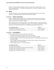
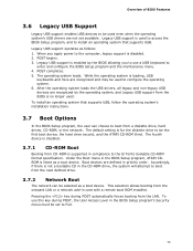
... loads the USB drivers, all legacy and non-legacy USB devices are recognized by the BIOS allowing you apply power to the computer, legacy support is not a bootable CD in card with a remote boot ROM installed. Under the Boot menu in the BIOS Setup program's Security menu must be set to Full. 73 Pressing the key during POST, the User Access Level in the BIOS Setup program, ATAPI CDROM is loading, USB keyboards and mice are recognized and may be used...
... loads the USB drivers, all legacy and non-legacy USB devices are recognized by the BIOS allowing you apply power to the computer, legacy support is not a bootable CD in card with a remote boot ROM installed. Under the Boot menu in the BIOS Setup program's Security menu must be set to Full. 73 Pressing the key during POST, the User Access Level in the BIOS Setup program, ATAPI CDROM is loading, USB keyboards and mice are recognized and may be used...
Product Specification
Page 76
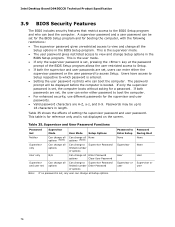
... User Password Functions Password Set Supervisor Mode User Mode Setup Options Neither Can change all Can change all None options (Note) options (Note) Supervisor only Can change all the Setup options in the BIOS Setup program. Intel Desktop Board D945GCCR Technical Product Specification 3.9 BIOS Security Features The BIOS includes security features that restrict access to 16 characters in length. Users have access to Setup respective to boot the computer. • For enhanced security, use different passwords for reference only and is entered...
... User Password Functions Password Set Supervisor Mode User Mode Setup Options Neither Can change all Can change all None options (Note) options (Note) Supervisor only Can change all the Setup options in the BIOS Setup program. Intel Desktop Board D945GCCR Technical Product Specification 3.9 BIOS Security Features The BIOS includes security features that restrict access to 16 characters in length. Users have access to Setup respective to boot the computer. • For enhanced security, use different passwords for reference only and is entered...
Product Specification
Page 78
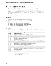
... be installed in card, often called a POST card. Input devices: Keyboard/Mouse. 9F is useful for determining the point where an error occurred. FF: FF processor exception. Intel Desktop Board D945GCCR Technical Product Specification 4.4 Port 80h POST Codes During the POST, the BIOS generates diagnostic progress codes (POST-codes) to I /O Busses: PCI, USB, ISA, ATA, etc. 5F is an unrecoverable error. Displaying the POST-codes requires a PCI bus add-in PCI bus connector 1. BF C0 - Host Processors: 1F is no memory detected or no useful memory...
... be installed in card, often called a POST card. Input devices: Keyboard/Mouse. 9F is useful for determining the point where an error occurred. FF: FF processor exception. Intel Desktop Board D945GCCR Technical Product Specification 4.4 Port 80h POST Codes During the POST, the BIOS generates diagnostic progress codes (POST-codes) to I /O Busses: PCI, USB, ISA, ATA, etc. 5F is an unrecoverable error. Displaying the POST-codes requires a PCI bus add-in PCI bus connector 1. BF C0 - Host Processors: 1F is no memory detected or no useful memory...
Product Specification
Page 79
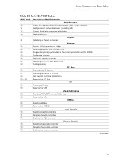
... memory settings Initializing memory, such as ECC init Testing memory PCI Bus Enumerating PCI busses Allocating resources to PCI bus Hot Plug PCI controller initialization Reserved for PCI Bus USB Resetting USB bus Reserved for USB ATA/ATAPI/SATA Resetting PATA/SATA bus and all devices Reserved for ATA SMBus Resetting SMBUS Reserved for SMBUS Local Console Resetting the VGA controller Disabling the VGA controller Enabling the VGA controller Remote Console Resetting the console controller Disabling the console controller Enabling the console controller continued 79 Error Messages and Beep...
... memory settings Initializing memory, such as ECC init Testing memory PCI Bus Enumerating PCI busses Allocating resources to PCI bus Hot Plug PCI controller initialization Reserved for PCI Bus USB Resetting USB bus Reserved for USB ATA/ATAPI/SATA Resetting PATA/SATA bus and all devices Reserved for ATA SMBus Resetting SMBUS Reserved for SMBUS Local Console Resetting the VGA controller Disabling the VGA controller Enabling the VGA controller Remote Console Resetting the console controller Disabling the console controller Enabling the console controller continued 79 Error Messages and Beep...


