Product Specification
Page 7
...120 4.4.8 USB Configuration Submenu 121 4.4.9 Chipset Configuration Submenu 122 4.4.10 Fan Control Configuration Submenu 124 4.4.11 Hardware Monitoring 125 4.5 Security Menu ...126 4.6 Power Menu ...127 4.6.1 ACPI Submenu 127 4.7 Boot Menu ...128 4.7.1 Boot Device Priority Submenu 129 4.7.2 Hard Disk Drives Submenu 130 4.7.3 Removable Devices Submenu 130 4.7.4 ATAPI CD-ROM Drives Submenu 131 4.8 Exit Menu ...131 5 Error Messages and Beep Codes 5.1 BIOS Error Messages 133 5.2 Port 80h POST Codes 135 5.3 Bus Initialization Checkpoints 139 5.4 Speaker ...140 5.5 BIOS Beep Codes ...140...
...120 4.4.8 USB Configuration Submenu 121 4.4.9 Chipset Configuration Submenu 122 4.4.10 Fan Control Configuration Submenu 124 4.4.11 Hardware Monitoring 125 4.5 Security Menu ...126 4.6 Power Menu ...127 4.6.1 ACPI Submenu 127 4.7 Boot Menu ...128 4.7.1 Boot Device Priority Submenu 129 4.7.2 Hard Disk Drives Submenu 130 4.7.3 Removable Devices Submenu 130 4.7.4 ATAPI CD-ROM Drives Submenu 131 4.8 Exit Menu ...131 5 Error Messages and Beep Codes 5.1 BIOS Error Messages 133 5.2 Port 80h POST Codes 135 5.3 Bus Initialization Checkpoints 139 5.4 Speaker ...140 5.5 BIOS Beep Codes ...140...
Product Specification
Page 8
... Specifications ...18 5. Characteristics of Single Channel Configuration without Dynamic Mode.....24 8. LAN Connector LED Locations 47 15. Back Panel Connectors 69 19. Connection Diagram for S/PDIF Back Panel Connector 44 12. Manufacturing Options 13 4. Supported System Bus Frequency and Memory Speed Combinations 22 6. Video BIOS Video Modes Supported for DDR266 Single Channel Configuration 35 viii Supported Modes for Analog CRTs 32 10. Example of the Standby Power Indicator LED on the D865GBF Board 56 17. Back Panel Audio Connector Options for DDR266 Dual Channel...
... Specifications ...18 5. Characteristics of Single Channel Configuration without Dynamic Mode.....24 8. LAN Connector LED Locations 47 15. Back Panel Connectors 69 19. Connection Diagram for S/PDIF Back Panel Connector 44 12. Manufacturing Options 13 4. Supported System Bus Frequency and Memory Speed Combinations 22 6. Video BIOS Video Modes Supported for DDR266 Single Channel Configuration 35 viii Supported Modes for Analog CRTs 32 10. Example of the Standby Power Indicator LED on the D865GBF Board 56 17. Back Panel Audio Connector Options for DDR266 Dual Channel...

Product Specification
Page 9
... 46. Fan Connector Current Capability 88 45. Desktop Board D865GBF/D865GLC Environmental Specifications 92 48. Main Menu...107 57. Peripheral Configuration Submenu 112 ix Wake-up Devices and Events 52 18. SCSI Hard Drive Activity LED Connector (Optional 78 36. Serial ATA Connectors 78 37. Front Panel Audio Connector/Jumper Block 84 42. Thermal Considerations for a One-Color Power LED 81 40. MTBF Calculations ...92 47. BIOS Setup Program Menu Bar 105 54. System Memory Map 61...
... 46. Fan Connector Current Capability 88 45. Desktop Board D865GBF/D865GLC Environmental Specifications 92 48. Main Menu...107 57. Peripheral Configuration Submenu 112 ix Wake-up Devices and Events 52 18. SCSI Hard Drive Activity LED Connector (Optional 78 36. Serial ATA Connectors 78 37. Front Panel Audio Connector/Jumper Block 84 42. Thermal Considerations for a One-Color Power LED 81 40. MTBF Calculations ...92 47. BIOS Setup Program Menu Bar 105 54. System Memory Map 61...
Product Specification
Page 13
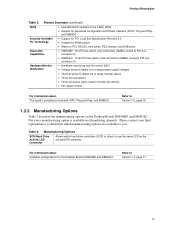
... power supply voltages • Thermal sense to detect out of range thermal values • Three fan connectors • Three fan sense inputs used to monitor fan activity • Fan speed control For information about Available configurations for PCI Local Bus Specification Revision 2.2 • Suspend to RAM support • Wake on the Desktop Boards D865GBF and D865GLC. Manufacturing Options SCSI Hard Drive Activity LED Connector Allows add-in hard drive controllers (SCSI or other) to you. Feature Summary (continued) BIOS • Intel...
... power supply voltages • Thermal sense to detect out of range thermal values • Three fan connectors • Three fan sense inputs used to monitor fan activity • Fan speed control For information about Available configurations for PCI Local Bus Specification Revision 2.2 • Suspend to RAM support • Wake on the Desktop Boards D865GBF and D865GLC. Manufacturing Options SCSI Hard Drive Activity LED Connector Allows add-in hard drive controllers (SCSI or other) to you. Feature Summary (continued) BIOS • Intel...
Product Specification
Page 16
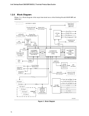
...Bus VGA Port Channel A DIMMs (2) Channel B DIMMs (2) Display Interface Dual-Channel Memory Bus SMBus PCI Bus PCI Slot 1 PCI Slot 2 PCI Slot 3 PCI Slot 4 PCI Slot 5 PCI Slot 6 SMBus D865GBF Only Hardware Monitoring and Fan Control ASIC USB LPC Bus I/O Controller LPC Bus Back Panel/ Front Panel USB Ports Serial Port Parallel Port PS/2 Mouse PS/2 Keyboard Diskette Drive Connector Intel 82801EB I/O Controller Hub (ICH5) Intel 82802AB 4 Mbit Firmware Hub (FWH) Intel 865G Chipset CSMA/CD Unit Interface 10/100 LAN PLC (Optional) LAN Connector AC Link Serial ATA IDE Interface Serial...
...Bus VGA Port Channel A DIMMs (2) Channel B DIMMs (2) Display Interface Dual-Channel Memory Bus SMBus PCI Bus PCI Slot 1 PCI Slot 2 PCI Slot 3 PCI Slot 4 PCI Slot 5 PCI Slot 6 SMBus D865GBF Only Hardware Monitoring and Fan Control ASIC USB LPC Bus I/O Controller LPC Bus Back Panel/ Front Panel USB Ports Serial Port Parallel Port PS/2 Mouse PS/2 Keyboard Diskette Drive Connector Intel 82801EB I/O Controller Hub (ICH5) Intel 82802AB 4 Mbit Firmware Hub (FWH) Intel 865G Chipset CSMA/CD Unit Interface 10/100 LAN PLC (Optional) LAN Connector AC Link Serial ATA IDE Interface Serial...
Product Specification
Page 41
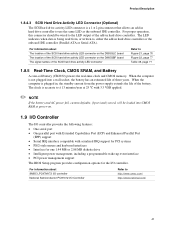
... mouse and keyboard interfaces • Interface for one 1.44 MB or 2.88 MB diskette drive • Intelligent power management, including a programmable wake-up event interface • PCI power management support The BIOS Setup program provides configuration options for the I /O Controller Refer to use the same LED as the onboard IDE controller. For information about The location of the SCSI hard drive activity LED connector on the D865GLC board The location of the battery. The LED indicates...
... mouse and keyboard interfaces • Interface for one 1.44 MB or 2.88 MB diskette drive • Intelligent power management, including a programmable wake-up event interface • PCI power management support The BIOS Setup program provides configuration options for the I /O Controller Refer to use the same LED as the onboard IDE controller. For information about The location of the SCSI hard drive activity LED connector on the D865GLC board The location of the battery. The LED indicates...
Product Specification
Page 68
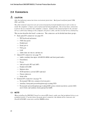
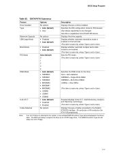
...; PS/2 keyboard and mouse USB (four ports) Parallel port Serial port A VGA port LAN Audio (line out, line in, and mic in) • Internal I/O connectors (see page 70) Audio (auxiliary line input, ATAPI CD-ROM, and front panel audio) Fans [three] Power Add-in boards (PCI and AGP) Parallel ATA IDE Diskette drive SCSI hard drive activity LED (optional) Chassis intrusion Serial ATA...
...; PS/2 keyboard and mouse USB (four ports) Parallel port Serial port A VGA port LAN Audio (line out, line in, and mic in) • Internal I/O connectors (see page 70) Audio (auxiliary line input, ATAPI CD-ROM, and front panel audio) Fans [three] Power Add-in boards (PCI and AGP) Parallel ATA IDE Diskette drive SCSI hard drive activity LED (optional) Chassis intrusion Serial ATA...
Product Specification
Page 76
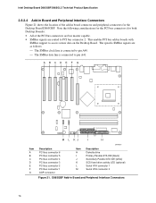
...connected to pin A41. Note the following considerations for the PCI bus connectors (for both Desktop Boards): • All of the add-in board connector and peripheral connectors for the Desktop Board D865GBF. A BCDE F G Item A B C D E F G 2 1 1 2 1 M L KJ 40 39 2 34 33 39 1 I H Description PCI bus connector 6 PCI bus connector 5 PCI bus connector 4 PCI bus connector 3 PCI bus connector 2 PCI bus connector 1 AGP connector Item H I J K L M OM15921 Description Diskette drive Primary Parallel ATA IDE [black] Secondary Parallel ATA IDE [white] SCSI hard drive activity LED (optional...
...connected to pin A41. Note the following considerations for the PCI bus connectors (for both Desktop Boards): • All of the add-in board connector and peripheral connectors for the Desktop Board D865GBF. A BCDE F G Item A B C D E F G 2 1 1 2 1 M L KJ 40 39 2 34 33 39 1 I H Description PCI bus connector 6 PCI bus connector 5 PCI bus connector 4 PCI bus connector 3 PCI bus connector 2 PCI bus connector 1 AGP connector Item H I J K L M OM15921 Description Diskette drive Primary Parallel ATA IDE [black] Secondary Parallel ATA IDE [white] SCSI hard drive activity LED (optional...
Product Specification
Page 98
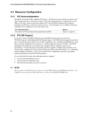
Intel Desktop Board D865GBF/D865GLC Technical Product Specification 3.3 Resource Configuration 3.3.1 PCI Autoconfiguration The BIOS can override the auto-configuration options by the add-in cards. PCI devices may be available for use ATA-66/100 features the following items are automatically configured for the supported version of the drive. When a user turns on the system after adding a PCI card, the BIOS automatically configures interrupts, the I /O channel support. The BIOS determines the capabilities of PCI and Plug and Play supported by the...
Intel Desktop Board D865GBF/D865GLC Technical Product Specification 3.3 Resource Configuration 3.3.1 PCI Autoconfiguration The BIOS can override the auto-configuration options by the add-in cards. PCI devices may be available for use ATA-66/100 features the following items are automatically configured for the supported version of the drive. When a user turns on the system after adding a PCI card, the BIOS automatically configures interrupts, the I /O channel support. The BIOS determines the capabilities of PCI and Plug and Play supported by the...
Product Specification
Page 105
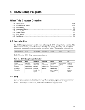
... power supply controls Selects boot options Exit Saves or discards changes to put the Desktop Board in configure mode. 4 BIOS Setup Program What This Chapter Contains 4.1 Introduction...105 4.2 Maintenance Menu 106 4.3 Main Menu...107 4.4 Advanced Menu...108 4.5 Security Menu ...126 4.6 Power Menu ...127 4.7 Boot Menu ...128 4.8 Exit Menu ...131 4.1 Introduction The BIOS Setup program can be used to view and change the BIOS settings for the computer. The BIOS Setup program is accessed by pressing the key after the Power-On Self-Test (POST) memory...
... power supply controls Selects boot options Exit Saves or discards changes to put the Desktop Board in configure mode. 4 BIOS Setup Program What This Chapter Contains 4.1 Introduction...105 4.2 Maintenance Menu 106 4.3 Main Menu...107 4.4 Advanced Menu...108 4.5 Security Menu ...126 4.6 Power Menu ...127 4.7 Boot Menu ...128 4.8 Exit Menu ...131 4.1 Introduction The BIOS Setup program can be used to view and change the BIOS settings for the computer. The BIOS Setup program is accessed by pressing the key after the Power-On Self-Test (POST) memory...
Product Specification
Page 106
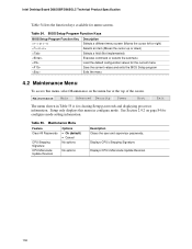
... top of the screen. Table 55. Intel Desktop Board D865GBF/D865GLC Technical Product Specification Table 54 lists the function keys available for configure mode setting information. Maintenance Menu Feature Options Clear All Passwords CPU Stepping Signature • Ok (default) • Cancel No options CPU Microcode Update Revision No options Description Clears the user and supervisor passwords. Displays CPU's Microcode Update Revision. 106 BIOS Setup Program Function Keys BIOS Setup Program Function Key or or Description Selects a different menu screen (Moves the...
... top of the screen. Table 55. Intel Desktop Board D865GBF/D865GLC Technical Product Specification Table 54 lists the function keys available for configure mode setting information. Maintenance Menu Feature Options Clear All Passwords CPU Stepping Signature • Ok (default) • Cancel No options CPU Microcode Update Revision No options Description Clears the user and supervisor passwords. Displays CPU's Microcode Update Revision. 106 BIOS Setup Program Function Keys BIOS Setup Program Function Key or or Description Selects a different menu screen (Moves the...
Product Specification
Page 113
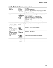
.../2-compatible mode. • ECP EPP is set to ECP) Audio Onboard LAN Options Description • Disabled Configures the parallel port. • Enabled Auto assigns LPT1 the address 378h and the interrupt IRQ7. • Auto (default) An * (asterisk) displayed next to an address indicates a conflict with another device. • Output Only Selects the mode for the parallel port. BIOS Setup Program Table 60. ECP is Enhanced Capabilities Port mode, a high-speed bi-directional mode. • 378 (default...
.../2-compatible mode. • ECP EPP is set to ECP) Audio Onboard LAN Options Description • Disabled Configures the parallel port. • Enabled Auto assigns LPT1 the address 378h and the interrupt IRQ7. • Auto (default) An * (asterisk) displayed next to an address indicates a conflict with another device. • Output Only Selects the mode for the parallel port. BIOS Setup Program Table 60. ECP is Enhanced Capabilities Port mode, a high-speed bi-directional mode. • 378 (default...
Product Specification
Page 117
... type of drive installed. The BIOS will be displayed in capabilities from ATA/ATAPI device. Specifies the IDE configuration mode for the drive. Auto fills-in the above table. Note: If an LS-120 drive is set to User.) Enables/disables S.M.A.R.T. (Self-Monitoring, Analysis, and Reporting Technology). (This item is read -only unless Type is set to the Parallel ATA IDE interface: 40-conductor or 80-conductor (for ATA-100 peripherals). SATA...
... type of drive installed. The BIOS will be displayed in capabilities from ATA/ATAPI device. Specifies the IDE configuration mode for the drive. Auto fills-in the above table. Note: If an LS-120 drive is set to User.) Enables/disables S.M.A.R.T. (Self-Monitoring, Analysis, and Reporting Technology). (This item is read -only unless Type is set to the Parallel ATA IDE interface: 40-conductor or 80-conductor (for ATA-100 peripherals). SATA...
Product Specification
Page 118
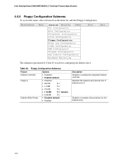
...; Disabled (default) • Enabled Description Disables or enables the integrated diskette controller. Specifies the capacity and physical size of diskette drive A. Table 63. Disables or enables write protection for configuring the diskette drive. Maintenance Main Advanced Security Power PCI Configuration Boot Configuration Peripheral Configuration Drive Configuration Floppy Configuration Event Log Configuration Video Configuration USB Configuration Chipset Configuration Fan Control Configuration Hardware Monitoring Boot Exit The submenu represented by Table 63 is used for...
...; Disabled (default) • Enabled Description Disables or enables the integrated diskette controller. Specifies the capacity and physical size of diskette drive A. Table 63. Disables or enables write protection for configuring the diskette drive. Maintenance Main Advanced Security Power PCI Configuration Boot Configuration Peripheral Configuration Drive Configuration Floppy Configuration Event Log Configuration Video Configuration USB Configuration Chipset Configuration Fan Control Configuration Hardware Monitoring Boot Exit The submenu represented by Table 63 is used for...
Product Specification
Page 123
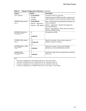
...; Disabled • Auto (default) • Manual - Selects the length of detected SDRAM settings. This option is displayed only if the installed processor has an 800 MHz system bus. 4. Manual - Notes: 1. This feature is displayed only if SDRAM Timing Control is set to attempt chip select assertions in memory. Enabled allows the DRAM controller to Manual - User Defined = Allows manual override of time required before accessing a new row. This feature is displayed only if Extended Configuration...
...; Disabled • Auto (default) • Manual - Selects the length of detected SDRAM settings. This option is displayed only if the installed processor has an 800 MHz system bus. 4. Manual - Notes: 1. This feature is displayed only if SDRAM Timing Control is set to attempt chip select assertions in memory. Enabled allows the DRAM controller to Manual - User Defined = Allows manual override of time required before accessing a new row. This feature is displayed only if Extended Configuration...

Product Specification
Page 124
... PCI Configuration Boot Configuration Peripheral Configuration Drive Configuration Floppy Configuration Event Log Configuration Video Configuration USB Configuration Chipset Configuration Fan Control Configuration Hardware Monitoring Boot Exit The submenu represented in Table 68 is for configuring fan control options. After saving the BIOS settings and turning off . Table 68. Intel Desktop Board D865GBF/D865GLC Technical Product Specification 4.4.10 Fan Control Configuration Submenu To access this menu, select Advanced on . 124 When set to Off, at low system temperatures the fans...
... PCI Configuration Boot Configuration Peripheral Configuration Drive Configuration Floppy Configuration Event Log Configuration Video Configuration USB Configuration Chipset Configuration Fan Control Configuration Hardware Monitoring Boot Exit The submenu represented in Table 68 is for configuring fan control options. After saving the BIOS settings and turning off . Table 68. Intel Desktop Board D865GBF/D865GLC Technical Product Specification 4.4.10 Fan Control Configuration Submenu To access this menu, select Advanced on . 124 When set to Off, at low system temperatures the fans...

Product Specification
Page 128
... 73 is used to set the boot features and the boot sequence. Specifies the boot sequence from the available ATAPI CD-ROM drives. 128 Enabled displays OEM graphic instead of the screen. Enables the computer to display submenu Description Disabled displays normal POST messages. Specifies the boot sequence from the available removable devices. Boot Menu Feature Silent Boot Intel(R) Rapid BIOS Boot PXE Boot to LAN USB Boot Boot Device Priority Hard Disk Drives Removable Devices ATAPI CD-ROM Drives Options • Disabled • Enabled (default) • Disabled • Enabled...
... 73 is used to set the boot features and the boot sequence. Specifies the boot sequence from the available ATAPI CD-ROM drives. 128 Enabled displays OEM graphic instead of the screen. Enables the computer to display submenu Description Disabled displays normal POST messages. Specifies the boot sequence from the available removable devices. Boot Menu Feature Silent Boot Intel(R) Rapid BIOS Boot PXE Boot to LAN USB Boot Boot Device Priority Hard Disk Drives Removable Devices ATAPI CD-ROM Drives Options • Disabled • Enabled (default) • Disabled • Enabled...
Product Specification
Page 135
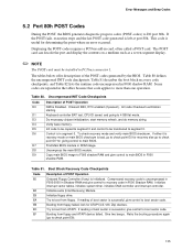
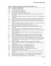
... control to recovery code in F000 Shadow RAM. Uncompress the main BIOS module. Boot Block Recovery Code Checkpoints Code E0 E8 Description of POST Operation NMI is successful, give control to be installed in PCI bus connector 1. Give two beeps. Keyboard controller BAT test, CPU ID saved, and going to boot from floppy. Control is left at port 80h. EC Try to 4 GB flat mode. If reading of the POST codes generated by the BIOS. Displaying the POST-codes requires a PCI bus add...
... control to recovery code in F000 Shadow RAM. Uncompress the main BIOS module. Boot Block Recovery Code Checkpoints Code E0 E8 Description of POST Operation NMI is successful, give control to be installed in PCI bus connector 1. Give two beeps. Keyboard controller BAT test, CPU ID saved, and going to boot from floppy. Control is left at port 80h. EC Try to 4 GB flat mode. If reading of the POST codes generated by the BIOS. Displaying the POST-codes requires a PCI bus add...
Product Specification
Page 137
... clear memory below 1M memory. Memory below 1M cleared. (SOFT RESET) Going to relocation/ shadow. Going to be updated during memory test. To enter in progress. 80 Keyboard test started . Going to check for diagnostics mode. Runtime Code Uncompressed in base memory. Going to adjust displayed memory size for memory test. Pattern to disable gate A20 line and disable parity/NMI. 57 A20 address line, parity/NMI disable successful. Error Messages and Beep Codes...
... clear memory below 1M memory. Memory below 1M cleared. (SOFT RESET) Going to relocation/ shadow. Going to be updated during memory test. To enter in progress. 80 Keyboard test started . Going to check for diagnostics mode. Runtime Code Uncompressed in base memory. Going to adjust displayed memory size for memory test. Pattern to disable gate A20 line and disable parity/NMI. 57 A20 address line, parity/NMI disable successful. Error Messages and Beep Codes...
Product Specification
Page 140
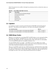
... Desktop Board D865GBF and the Desktop Board D865GLC. Intel Desktop Board D865GBF/D865GLC Technical Product Specification Table 85 describes the lower nibble of the high byte and indicates the bus on page 15 5.5 BIOS Beep Codes Whenever a recoverable error occurs during POST, the BIOS displays an error message describing the problem (see Table 86). The speaker provides audible error code (beep code) information during POST if the video configuration fails (a faulty video card or no card installed) or if an external ROM...
... Desktop Board D865GBF and the Desktop Board D865GLC. Intel Desktop Board D865GBF/D865GLC Technical Product Specification Table 85 describes the lower nibble of the high byte and indicates the bus on page 15 5.5 BIOS Beep Codes Whenever a recoverable error occurs during POST, the BIOS displays an error message describing the problem (see Table 86). The speaker provides audible error code (beep code) information during POST if the video configuration fails (a faulty video card or no card installed) or if an external ROM...


