Product Specification
Page 6
... BIOS Flash Memory Organization 62 3.3 Resource Configuration 62 3.3.1 PCI* Autoconfiguration 62 3.4 System Management BIOS (SMBIOS 63 3.5 Legacy USB Support 64 3.6 BIOS Updates 65 3.6.1 BIOS Recovery 65 3.6.2 Custom Splash Screen 66 3.7 Boot Options 66 3.7.1 Optical Drive Boot 66 3.7.2 Network Boot 66 3.7.3 Booting Without Attached Devices 67 3.7.4 Changing the Default Boot Device During POST 67 3.8 BIOS Security Features 68 4 Board Status and Error Messages 69 4.1 BIOS Beep Codes 69 4.2 Front-panel Power LED Blink Codes 70 4.3 BIOS Error Messages 70 4.4 Port 80h POST Codes...
... BIOS Flash Memory Organization 62 3.3 Resource Configuration 62 3.3.1 PCI* Autoconfiguration 62 3.4 System Management BIOS (SMBIOS 63 3.5 Legacy USB Support 64 3.6 BIOS Updates 65 3.6.1 BIOS Recovery 65 3.6.2 Custom Splash Screen 66 3.7 Boot Options 66 3.7.1 Optical Drive Boot 66 3.7.2 Network Boot 66 3.7.3 Booting Without Attached Devices 67 3.7.4 Changing the Default Boot Device During POST 67 3.8 BIOS Security Features 68 4 Board Status and Error Messages 69 4.1 BIOS Beep Codes 69 4.2 Front-panel Power LED Blink Codes 70 4.3 BIOS Error Messages 70 4.4 Port 80h POST Codes...

Product Specification
Page 7
... Panel Audio Connectors 24 5. I/O Shield Reference Diagram 38 10. Localized High Temperature Zones 53 17. Serial Port Header 41 12. Thermal Sensors and Fan Header 26 6. LVDS Data Connector - 30-Pin (D425KTW only 41 13. Wake-up Devices and Events 29 9. Supported Memory Configurations 16 4. LVDS Inverter Power Voltage Selection Jumper (D425KTW only 42 16. Connection Diagram for Chassis Selection (Chassis Orientation is Not Restricted 56 Tables 1. Front Panel Audio Header for Front Panel USB Header with Intel Z-U130 USB Solid-State Drive or Compatible Device Support...
... Panel Audio Connectors 24 5. I/O Shield Reference Diagram 38 10. Localized High Temperature Zones 53 17. Serial Port Header 41 12. Thermal Sensors and Fan Header 26 6. LVDS Data Connector - 30-Pin (D425KTW only 41 13. Wake-up Devices and Events 29 9. Supported Memory Configurations 16 4. LVDS Inverter Power Voltage Selection Jumper (D425KTW only 42 16. Connection Diagram for Chassis Selection (Chassis Orientation is Not Restricted 56 Tables 1. Front Panel Audio Header for Front Panel USB Header with Intel Z-U130 USB Solid-State Drive or Compatible Device Support...
Product Specification
Page 8
.... Boot Device Menu Options 67 36. EMC Regulations 81 45. Power Connector 45 24. BIOS Configuration Jumper Settings 50 27. Thermal Considerations for BIOS Recovery 65 35. BIOS Setup Program Menu Bar 62 33. Port 80h POST Codes 72 42. Acceptable Drives/Media Types for Components 54 29. Maximum Load Configuration Current and Power Results 58 31. Intel Desktop Board D425KT and Intel Desktop Board D425KTW Environmental Specifications 59 32. Front-panel Power LED Blink Codes 70 39. Supervisor and User Password Functions 68 37. BIOS Error Messages...
.... Boot Device Menu Options 67 36. EMC Regulations 81 45. Power Connector 45 24. BIOS Configuration Jumper Settings 50 27. Thermal Considerations for BIOS Recovery 65 35. BIOS Setup Program Menu Bar 62 33. Port 80h POST Codes 72 42. Acceptable Drives/Media Types for Components 54 29. Maximum Load Configuration Current and Power Results 58 31. Intel Desktop Board D425KT and Intel Desktop Board D425KTW Environmental Specifications 59 32. Front-panel Power LED Blink Codes 70 39. Supervisor and User Password Functions 68 37. BIOS Error Messages...
Product Specification
Page 9
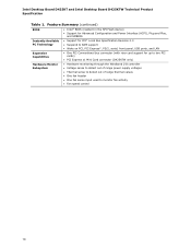
... panel cabling • Seven USB 2.0 ports (D425KTW only): ― Four back panel ports ― Two ports are implemented with an internal header (brown-colored) that supports an Intel® Z-U130 USB Solid-State Drive or compatible device • Two Serial ATA (SATA) 3.0 Gb/s connectors (supporting IDE and AHCI mode) • One parallel port connector on the back panel • One serial port connector on the back panel • One serial port header • PS/2*-style keyboard and mouse ports 10/100 Mbits/s Ethernet LAN subsystem using...
... panel cabling • Seven USB 2.0 ports (D425KTW only): ― Four back panel ports ― Two ports are implemented with an internal header (brown-colored) that supports an Intel® Z-U130 USB Solid-State Drive or compatible device • Two Serial ATA (SATA) 3.0 Gb/s connectors (supporting IDE and AHCI mode) • One parallel port connector on the back panel • One serial port connector on the back panel • One serial port header • PS/2*-style keyboard and mouse ports 10/100 Mbits/s Ethernet LAN subsystem using...
Product Specification
Page 10
Intel Desktop Board D425KT and Intel Desktop Board D425KTW Technical Product Specification Table 1. Feature Summary (continued) BIOS • Intel® BIOS (resident in the SPI Flash device) • Support for Advanced Configuration and Power Interface (ACPI), Plug and Play, and SMBIOS Instantly Available • Support for PCI* Local Bus Specification Revision 2.3 PC Technology • Suspend to RAM support • Wake on PCI, PCI Express*, PS/2, serial, front panel, USB ports, and LAN Expansion Capabilities • One PCI Conventional bus connector (with riser card support ...
Intel Desktop Board D425KT and Intel Desktop Board D425KTW Technical Product Specification Table 1. Feature Summary (continued) BIOS • Intel® BIOS (resident in the SPI Flash device) • Support for Advanced Configuration and Power Interface (ACPI), Plug and Play, and SMBIOS Instantly Available • Support for PCI* Local Bus Specification Revision 2.3 PC Technology • Suspend to RAM support • Wake on PCI, PCI Express*, PS/2, serial, front panel, USB ports, and LAN Expansion Capabilities • One PCI Conventional bus connector (with riser card support ...
Product Specification
Page 14
... Product Specification 1.2 Online Support To find information about Power supply connectors Refer to be passively cooled in a properly ventilated chassis. NOTE The board is designed to Section 2.2.2.3, page 45 14 Chassis venting locations are recommended above the processor heatsink area for the Intel Desktop Board D425KT and Intel Desktop Board D425KTW Supported processors Chipset information BIOS and driver updates Tested memory Integration information Visit this World Wide Web site: http://www.intel.com/products/motherboard/index...
... Product Specification 1.2 Online Support To find information about Power supply connectors Refer to be passively cooled in a properly ventilated chassis. NOTE The board is designed to Section 2.2.2.3, page 45 14 Chassis venting locations are recommended above the processor heatsink area for the Intel Desktop Board D425KT and Intel Desktop Board D425KTW Supported processors Chipset information BIOS and driver updates Tested memory Integration information Visit this World Wide Web site: http://www.intel.com/products/motherboard/index...
Product Specification
Page 16
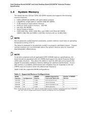
... "SS" refers to passively-cooled thermal constraints, system memory must have an operating temperature rating of SDRAM). 16 If nonSPD memory is designed to accurately configure memory settings for maximum heat dissipation effectiveness. Intel Desktop Board D425KT and Intel Desktop Board D425KTW Technical Product Specification 1.4 System Memory The board has two 204-pin DDR3 SO-DIMM sockets and supports the following memory features: • DDR3 SDRAM SO-DIMMs with...
... "SS" refers to passively-cooled thermal constraints, system memory must have an operating temperature rating of SDRAM). 16 If nonSPD memory is designed to accurately configure memory settings for maximum heat dissipation effectiveness. Intel Desktop Board D425KT and Intel Desktop Board D425KTW Technical Product Specification 1.4 System Memory The board has two 204-pin DDR3 SO-DIMM sockets and supports the following memory features: • DDR3 SDRAM SO-DIMMs with...
Product Specification
Page 19
... SATA controller supports IDE and AHCI configuration and can be installed on each port for configurations using the Windows* XP and Windows Vista* operating systems. For information about The location of the USB connectors on the back panel The location of the SATA connectors Refer to the cable. In native mode, standard PCI Conventional bus resource steering is as follows: • Eight USB 2.0 ports (D425KT only): ⎯ Four back panel ports ⎯ Four ports are implemented with two dual port internal headers...
... SATA controller supports IDE and AHCI configuration and can be installed on each port for configurations using the Windows* XP and Windows Vista* operating systems. For information about The location of the USB connectors on the back panel The location of the SATA connectors Refer to the cable. In native mode, standard PCI Conventional bus resource steering is as follows: • Eight USB 2.0 ports (D425KT only): ⎯ Four back panel ports ⎯ Four ports are implemented with two dual port internal headers...
Product Specification
Page 20
... panel • One parallel port connector with Extended Capabilities Port (ECP) and Enhanced Parallel Port (EPP) support • Serial IRQ interface compatible with an equivalent one. Intel Desktop Board D425KT and Intel Desktop Board D425KTW Technical Product Specification 1.6 Real-Time Clock Subsystem A coin-cell battery (CR2032) powers the real-time clock and CMOS memory. The clock is not plugged into CMOS RAM at 25 ºC with 3.3 VSB applied. NOTE If the battery and AC power fail, custom defaults...
... panel • One parallel port connector with Extended Capabilities Port (ECP) and Enhanced Parallel Port (EPP) support • Serial IRQ interface compatible with an equivalent one. Intel Desktop Board D425KT and Intel Desktop Board D425KTW Technical Product Specification 1.6 Real-Time Clock Subsystem A coin-cell battery (CR2032) powers the real-time clock and CMOS memory. The clock is not plugged into CMOS RAM at 25 ºC with 3.3 VSB applied. NOTE If the battery and AC power fail, custom defaults...

Product Specification
Page 27
...: • Software support through Advanced Configuration and Power Interface (ACPI) • Hardware support: ⎯ Power connector ⎯ Fan header ⎯ LAN wake capabilities ⎯ Instantly Available PC technology ⎯ Wake from USB ⎯ Wake from PS/2 devices ⎯ Power Management Event signal (PME#) wake-up support ⎯ WAKE# signal wake-up (ACPI G0 - ACPI features include: • Plug and Play (including bus and device enumeration) • Power management control of ACPI with the board requires an operating system that enables the operating...
...: • Software support through Advanced Configuration and Power Interface (ACPI) • Hardware support: ⎯ Power connector ⎯ Fan header ⎯ LAN wake capabilities ⎯ Instantly Available PC technology ⎯ Wake from USB ⎯ Wake from PS/2 devices ⎯ Power Management Event signal (PME#) wake-up support ⎯ WAKE# signal wake-up (ACPI G0 - ACPI features include: • Plug and Play (including bus and device enumeration) • Power management control of ACPI with the board requires an operating system that enables the operating...
Product Specification
Page 34
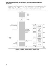
Detailed System Memory Address Map 34 Intel Desktop Board D425KT and Intel Desktop Board D425KTW Technical Product Specification The amount of system addresses. Figure 7. All installed system memory can be used when there is no overlap of installed memory that can be used will vary based on add-in cards and BIOS settings. Figure 7 shows a schematic of the system memory map.
Detailed System Memory Address Map 34 Intel Desktop Board D425KT and Intel Desktop Board D425KTW Technical Product Specification The amount of system addresses. Figure 7. All installed system memory can be used when there is no overlap of installed memory that can be used will vary based on add-in cards and BIOS settings. Figure 7 shows a schematic of the system memory map.
Product Specification
Page 40
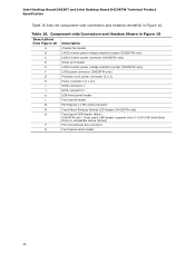
... panel USB header supports Intel Z-U130 USB Solid-State Drive or compatible device (brown) P PCI conventional bus connector Q Front panel audio header 40 Intel Desktop Board D425KT and Intel Desktop Board D425KTW Technical Product Specification Table 10 lists the component-side connectors and headers identified in Figure 10 Item/callout from Figure 10 Description A Chassis fan header B LVDS inverter panel voltage selection jumper (D425KTW only) C LVDS inverter power connector (D425KTW only) D Serial port header E LVDS inverter power voltage selection jumper (D425KTW...
... panel USB header supports Intel Z-U130 USB Solid-State Drive or compatible device (brown) P PCI conventional bus connector Q Front panel audio header 40 Intel Desktop Board D425KT and Intel Desktop Board D425KTW Technical Product Specification Table 10 lists the component-side connectors and headers identified in Figure 10 Item/callout from Figure 10 Description A Chassis fan header B LVDS inverter panel voltage selection jumper (D425KTW only) C LVDS inverter power connector (D425KTW only) D Serial port header E LVDS inverter power voltage selection jumper (D425KTW...
Product Specification
Page 48
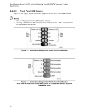
Connection Diagram for Front Panel USB Header with Intel Z-U130 USB Solid-State Drive or Compatible Device Support (D425KTW only) 48 Connection Diagram for Front Panel USB Header Figure 13. NOTE • The +5 VDC power on the USB headers is fused. • Use only a front panel USB connector that conforms to the USB 2.0 specification for the front panel USB headers. Figure 12. Intel Desktop Board D425KT and Intel Desktop Board D425KTW Technical Product Specification 2.2.2.5 Front Panel USB Headers Figure 12 and Figure 13 are connection diagrams for high-speed USB devices.
Connection Diagram for Front Panel USB Header with Intel Z-U130 USB Solid-State Drive or Compatible Device Support (D425KTW only) 48 Connection Diagram for Front Panel USB Header Figure 13. NOTE • The +5 VDC power on the USB headers is fused. • Use only a front panel USB connector that conforms to the USB 2.0 specification for the front panel USB headers. Figure 12. Intel Desktop Board D425KT and Intel Desktop Board D425KTW Technical Product Specification 2.2.2.5 Front Panel USB Headers Figure 12 and Figure 13 are connection diagrams for high-speed USB devices.
Product Specification
Page 61
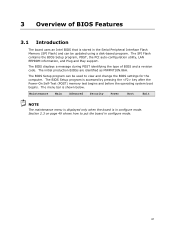
... Flash contains the BIOS Setup program, POST, the PCI auto-configuration utility, LAN EEPROM information, and Plug and Play support. The initial production BIOSs are identified as MWPNT10N.86A. The menu bar is accessed by pressing the key after the Power-On Self-Test (POST) memory test begins and before the operating system boot begins. The BIOS displays a message during POST identifying the type of BIOS Features 3.1 Introduction The board uses an Intel BIOS that is in configure mode...
... Flash contains the BIOS Setup program, POST, the PCI auto-configuration utility, LAN EEPROM information, and Plug and Play support. The initial production BIOSs are identified as MWPNT10N.86A. The menu bar is accessed by pressing the key after the Power-On Self-Test (POST) memory test begins and before the operating system boot begins. The BIOS displays a message during POST identifying the type of BIOS Features 3.1 Introduction The board uses an Intel BIOS that is in configure mode...
Product Specification
Page 62
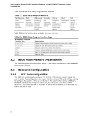
... lets a user insert or remove PCI cards without having to be onboard or add-in cards. Any interrupts set to Available in card. 62 BIOS Setup Program Menu Bar Maintenance Main Advanced Security Clears passwords and displays processor information Displays processor and memory configuration Configures advanced features available through the chipset Sets passwords and security features Power Boot Configures power management features and power states options Selects boot options Exit Saves or discards changes to Setup program options Table 33 lists the function keys available for...
... lets a user insert or remove PCI cards without having to be onboard or add-in cards. Any interrupts set to Available in card. 62 BIOS Setup Program Menu Bar Maintenance Main Advanced Security Clears passwords and displays processor information Displays processor and memory configuration Configures advanced features available through the chipset Sets passwords and security features Power Boot Configures power management features and power states options Selects boot options Exit Saves or discards changes to Setup program options Table 33 lists the function keys available for...

Product Specification
Page 66
... with a remote boot ROM installed. The default setting is supported in the BIOS Setup program's Security menu must be used to boot from the LAN. Under the Boot menu in priority order. This splash screen can choose to create a custom splash screen. Intel Desktop Board D425KT and Intel Desktop Board D425KTW Technical Product Specification 3.6.2 Custom Splash Screen During POST, an Intel® splash screen is listed as a boot device. To use this key during POST automatically forces booting from a hard drive, optical drive, removable drive, or the network. NOTE If...
... with a remote boot ROM installed. The default setting is supported in the BIOS Setup program's Security menu must be used to boot from the LAN. Under the Boot menu in priority order. This splash screen can choose to create a custom splash screen. Intel Desktop Board D425KT and Intel Desktop Board D425KTW Technical Product Specification 3.6.2 Custom Splash Screen During POST, an Intel® splash screen is listed as a boot device. To use this key during POST automatically forces booting from a hard drive, optical drive, removable drive, or the network. NOTE If...
Product Specification
Page 68
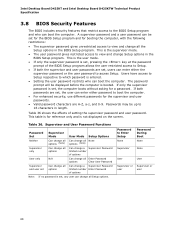
... password and user password. A supervisor password and a user password can be set for the BIOS Setup program and for the supervisor and user passwords. • Valid password characters are set , the user can enter either password to boot the computer. • For enhanced security, use different passwords for booting the computer, with the following restrictions: • The supervisor password gives unrestricted access to view and change Setup options in length. Intel Desktop Board D425KT and Intel Desktop Board D425KTW Technical Product Specification 3.8 BIOS...
... password and user password. A supervisor password and a user password can be set for the BIOS Setup program and for the supervisor and user passwords. • Valid password characters are set , the user can enter either password to boot the computer. • For enhanced security, use different passwords for booting the computer, with the following restrictions: • The supervisor password gives unrestricted access to view and change Setup options in length. Intel Desktop Board D425KT and Intel Desktop Board D425KTW Technical Product Specification 3.8 BIOS...
Product Specification
Page 70
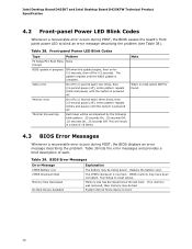
... VGA option ROM is complete. Run Setup to boot. 70 Table 39 lists the error messages and provides a brief description of 16 blinks. Table 39. System did not find a device to reset values. Intel Desktop Board D425KT and Intel Desktop Board D425KTW Technical Product Specification 4.2 Front-panel Power LED Blink Codes Whenever a recoverable error occurs during POST, the BIOS displays an error message describing the problem. Memory size has decreased since the last boot. Front-panel Power LED Blink Codes Type Pattern F2 Setup/F10 Boot Menu...
... VGA option ROM is complete. Run Setup to boot. 70 Table 39 lists the error messages and provides a brief description of 16 blinks. Table 39. System did not find a device to reset values. Intel Desktop Board D425KT and Intel Desktop Board D425KTW Technical Product Specification 4.2 Front-panel Power LED Blink Codes Whenever a recoverable error occurs during POST, the BIOS displays an error message describing the problem. Memory size has decreased since the last boot. Front-panel Power LED Blink Codes Type Pattern F2 Setup/F10 Boot Menu...

Product Specification
Page 71
... stops and the last POST code generated is an unrecoverable error. Displaying the POST codes requires a PCI bus add-in the PCI bus connector. Port 80h POST Code Ranges Range Category/Subsystem 00 - 0F 10 - 1F Debug codes: Can be installed in card, often called a POST card. BF is left at port 80h. DF Boot device selection. F0 - Start with PCI. 60 - 6F Reserved for future use (for future use (new input console codes). B0 - CF Reserved...
... stops and the last POST code generated is an unrecoverable error. Displaying the POST codes requires a PCI bus add-in the PCI bus connector. Port 80h POST Code Ranges Range Category/Subsystem 00 - 0F 10 - 1F Debug codes: Can be installed in card, often called a POST card. BF is left at port 80h. DF Boot device selection. F0 - Start with PCI. 60 - 6F Reserved for future use (for future use (new input console codes). B0 - CF Reserved...

Product Specification
Page 74
Intel Desktop Board D425KT and Intel Desktop Board D425KTW Technical Product Specification Table 41. Port 80h POST Codes (continued) POST Code Description of POST Operation DXE Drivers E7 Waiting for user input E8 Checking password E9 Entering BIOS setup EB Calling Legacy Option ROMs Runtime Phase/EFI OS Boot F4 Entering Sleep state F5 Exiting Sleep state F8 EFI boot service ExitBootServices ( ) has been called F9 EFI runtime service SetVirtualAddressMap ( ) has been called FA EFI runtime service ResetSystem ( ) has been called...
Intel Desktop Board D425KT and Intel Desktop Board D425KTW Technical Product Specification Table 41. Port 80h POST Codes (continued) POST Code Description of POST Operation DXE Drivers E7 Waiting for user input E8 Checking password E9 Entering BIOS setup EB Calling Legacy Option ROMs Runtime Phase/EFI OS Boot F4 Entering Sleep state F5 Exiting Sleep state F8 EFI boot service ExitBootServices ( ) has been called F9 EFI runtime service SetVirtualAddressMap ( ) has been called FA EFI runtime service ResetSystem ( ) has been called...


