User Guide
Page 3
... General Guidelines 17 2.1.2.2 Heatsink Clip Load Requirement 17 2.1.2.3 Additional Guidelines 18 2.2 Thermal Requirements 18 2.2.1 Processor Case Temperature 18 2.2.2 Thermal Profile 19 2.2.3 TCONTROL 20 2.3 Heatsink Design Considerations 21 2.3.1 Heatsink Size 22 2.3.2 Heatsink Mass ...Performance Requirements 25 3.1.1 Example 26 3.2 Processor Thermal Solution Performance Assessment 27 3.3 Local Ambient Temperature Measurement Guidelines 27 3.4 Processor Case Temperature Measurement Guidelines 30 4 Thermal Management Logic and Thermal Monitor Feature 31 4.1 Processor Power ...
... General Guidelines 17 2.1.2.2 Heatsink Clip Load Requirement 17 2.1.2.3 Additional Guidelines 18 2.2 Thermal Requirements 18 2.2.1 Processor Case Temperature 18 2.2.2 Thermal Profile 19 2.2.3 TCONTROL 20 2.3 Heatsink Design Considerations 21 2.3.1 Heatsink Size 22 2.3.2 Heatsink Mass ...Performance Requirements 25 3.1.1 Example 26 3.2 Processor Thermal Solution Performance Assessment 27 3.3 Local Ambient Temperature Measurement Guidelines 27 3.4 Processor Case Temperature Measurement Guidelines 30 4 Thermal Management Logic and Thermal Monitor Feature 31 4.1 Processor Power ...
User Guide
Page 4
... Geometric Envelope for ATX Intel® Reference Thermal Mechanical Design ...... 45 5.6 ATX Reference Thermal Mechanical Solution for the Intel® Pentium® 4 Processor in the 775-Land LGA Package 46... 6.3 Board and System Implementation 55 6.3.1 Choosing Fan Speed Control Settings 55 6.3.1.1 Temperature to begin Fan Acceleration 56 6.3.1.2 Minimum PWM Duty Cycle 58 6.4 Combining Thermistor... 59 LGA775 Socket Heatsink Loading 61 A.1 LGA775 Socket Heatsink Considerations 61 A.2 Metric for Heatsink Preload for ATX/µATX Designs Non-Compliant with Intel Reference Design ...
... Geometric Envelope for ATX Intel® Reference Thermal Mechanical Design ...... 45 5.6 ATX Reference Thermal Mechanical Solution for the Intel® Pentium® 4 Processor in the 775-Land LGA Package 46... 6.3 Board and System Implementation 55 6.3.1 Choosing Fan Speed Control Settings 55 6.3.1.1 Temperature to begin Fan Acceleration 56 6.3.1.2 Minimum PWM Duty Cycle 58 6.4 Combining Thermistor... 59 LGA775 Socket Heatsink Loading 61 A.1 LGA775 Socket Heatsink Considerations 61 A.2 Metric for Heatsink Preload for ATX/µATX Designs Non-Compliant with Intel Reference Design ...
User Guide
Page 5
...67 B.1 Overview...67 B.2 Test Preparation 67 B.2.1 Heatsink Preparation 67 B.2.2 Typical Test Equipment 70 B.3 Test Procedure Examples 70 B.3.1 Time-Zero, Room Temperature Preload Measurement 71 B.3.2 Preload Degradation under Bake Conditions 71 Thermal Interface Management 73 C.1 Bond Line Management 73 C.2 Interface Material Area 73 C.3 Interface ... Requirements 87 Appendix F Balanced Technology Extended (BTX) System Thermal Considerations 91 Appendix G Mechanical Drawings...93 Appendix H Intel Enabled Reference Solution Information 105 Thermal/Mechanical Design Guide 5
...67 B.1 Overview...67 B.2 Test Preparation 67 B.2.1 Heatsink Preparation 67 B.2.2 Typical Test Equipment 70 B.3 Test Procedure Examples 70 B.3.1 Time-Zero, Room Temperature Preload Measurement 71 B.3.2 Preload Degradation under Bake Conditions 71 Thermal Interface Management 73 C.1 Bond Line Management 73 C.2 Interface Material Area 73 C.3 Interface ... Requirements 87 Appendix F Balanced Technology Extended (BTX) System Thermal Considerations 91 Appendix G Mechanical Drawings...93 Appendix H Intel Enabled Reference Solution Information 105 Thermal/Mechanical Design Guide 5
User Guide
Page 6
...of the Thermocouple 80 Figure 31. Position Bead on the 775-Land LGA Package 79 Figure 29. Measuring Resistance between Thermocouple...-out Footprint Definition and Height Restrictions for Measuring Local Ambient Temperature, Active Heatsink 29 Figure 6. Upward Board Deflection during Shock...Locations for Enabling Components - Using 3D Micromanipulator to the LGA775 Socket 79 Figure 30. IHS Groove Orientation Relative to Secure Bead ... Thermal/Mechanical Design Guide Intel® RCBFH-3 Reference Design 46 Figure 11. Intel® RCBFH-3 Reference Design (Exploded View ...
...of the Thermocouple 80 Figure 31. Position Bead on the 775-Land LGA Package 79 Figure 29. Measuring Resistance between Thermocouple...-out Footprint Definition and Height Restrictions for Measuring Local Ambient Temperature, Active Heatsink 29 Figure 6. Upward Board Deflection during Shock...Locations for Enabling Components - Using 3D Micromanipulator to the LGA775 Socket 79 Figure 30. IHS Groove Orientation Relative to Secure Bead ... Thermal/Mechanical Design Guide Intel® RCBFH-3 Reference Design 46 Figure 11. Intel® RCBFH-3 Reference Design (Exploded View ...
User Guide
Page 9
...system and the chassis characteristics, new system and component designs may result in irreversible changes in the operating characteristics of this temperature range a component is expected to meet its specified performance. All of these thermal characteristics and discuss guidelines for meeting ... including the processor, in the system. The result is an increased importance on single processor systems for the Intel® Pentium® 4 processor in the 775-Land LGA package. Thermal/Mechanical Design Guide 9 As operating frequencies increase and packaging size decreases, the power ...
...system and the chassis characteristics, new system and component designs may result in irreversible changes in the operating characteristics of this temperature range a component is expected to meet its specified performance. All of these thermal characteristics and discuss guidelines for meeting ... including the processor, in the system. The result is an increased importance on single processor systems for the Intel® Pentium® 4 processor in the 775-Land LGA package. Thermal/Mechanical Design Guide 9 As operating frequencies increase and packaging size decreases, the power ...
User Guide
Page 10
...DISSIPATION AND MAXIMUM CASE TEMPERATURE. On 90 nm Process in the 775-land LGA Package, supporting Intel® Extended Memory 64 TechnologyΦ, and supporting Intel® Virtualization Technology as appropriate. Introduction R 1.1.3 Document Scope This design guide supports the following processors: • Pentium 4 processors 570/... 530/531, and 520/521 in the 775land LGA package • Pentium 4 processor 670/672, 660/662, 650, 640, and 630 in the 775-land LGA package • Pentium 4 processor Extreme Edition in the 775-land LGA package In this document, when a reference is made to...
...DISSIPATION AND MAXIMUM CASE TEMPERATURE. On 90 nm Process in the 775-land LGA Package, supporting Intel® Extended Memory 64 TechnologyΦ, and supporting Intel® Virtualization Technology as appropriate. Introduction R 1.1.3 Document Scope This design guide supports the following processors: • Pentium 4 processors 570/... 530/531, and 520/521 in the 775land LGA package • Pentium 4 processor 670/672, 660/662, 650, 640, and 630 in the 775-land LGA package • Pentium 4 processor Extreme Edition in the 775-land LGA package In this document, when a reference is made to...
User Guide
Page 12
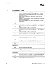
...Terms Term Description TA TC TE TS TC-MAX ΨCA ΨCS ΨSA TIM PMAX TDP IHS LGA775 Socket The measured ambient temperature locally surrounding the processor. Thermal Interface Material: The thermally conductive compound between a passive heatsink and any object that attempts ... of the topside of the fins to form a duct. Defined as specified in the 775- ACPI Advanced Configuration and Power Interface. Heatsink temperature measured on the Pentium 4 processor in the 775-land LGA package that can be designed to -ambient thermal characterization parameter (psi). Case...
...Terms Term Description TA TC TE TS TC-MAX ΨCA ΨCS ΨSA TIM PMAX TDP IHS LGA775 Socket The measured ambient temperature locally surrounding the processor. Thermal Interface Material: The thermally conductive compound between a passive heatsink and any object that attempts ... of the topside of the fins to form a duct. Defined as specified in the 775- ACPI Advanced Configuration and Power Interface. Heatsink temperature measured on the Pentium 4 processor in the 775-land LGA package that can be designed to -ambient thermal characterization parameter (psi). Case...

User Guide
Page 13
.... Introduction R Term Description FSC TCONTROL_BASE TCONTROL_OFFSET TCONTROL PWM Health Monitor Component BTX TMA Fan Speed Control: Thermal solution that is capable of reading the processor temperature and providing the PWM signal to the 4 pin fan header. The enabled 4 wire fans use with the on -die thermal diode as a reference to change...
.... Introduction R Term Description FSC TCONTROL_BASE TCONTROL_OFFSET TCONTROL PWM Health Monitor Component BTX TMA Fan Speed Control: Thermal solution that is capable of reading the processor temperature and providing the PWM signal to the 4 pin fan header. The enabled 4 wire fans use with the on -die thermal diode as a reference to change...
User Guide
Page 17
... design, in which it is required to Figure 45) • And no features on the LGA775 socket to directly attach a heatsink; Designs should provide a means for designs compliant with the Intel reference design assumptions: • 72 mm x 72 mm mounting hole span (refer to protect against...the Pentium 4 processor in the 775-land LGA package should create a static preload on top of the IHS, this mechanism plays a significant role in the robustness of socket solder joint in place on the package between the IHS and the heatsink. In addition to holding the heatsink in temperature ...
... design, in which it is required to Figure 45) • And no features on the LGA775 socket to directly attach a heatsink; Designs should provide a means for designs compliant with the Intel reference design assumptions: • 72 mm x 72 mm mounting hole span (refer to protect against...the Pentium 4 processor in the 775-land LGA package should create a static preload on top of the IHS, this mechanism plays a significant role in the robustness of socket solder joint in place on the package between the IHS and the heatsink. In addition to holding the heatsink in temperature ...
User Guide
Page 18
... In addition to the general guidelines given above, the heatsink attach mechanism for the Pentium 4 processor in the 775-land LGA package should be installed after reflow, given in the LGA775 Socket Mechanical Design Guide with its tolerances ⎯ The height of the package, from ... processor performance and acoustic noise reduction. 2.2.1 Processor Case Temperature For the Pentium 4 processor in this package. Intel has introduced a new method for specifying the thermal limits for a 37.5 mm x 37.5 mm [1.474 in x 1.474 in the 775-land LGA package. For illustration, Figure 2 shows the...
... In addition to the general guidelines given above, the heatsink attach mechanism for the Pentium 4 processor in the 775-land LGA package should be installed after reflow, given in the LGA775 Socket Mechanical Design Guide with its tolerances ⎯ The height of the package, from ... processor performance and acoustic noise reduction. 2.2.1 Processor Case Temperature For the Pentium 4 processor in this package. Intel has introduced a new method for specifying the thermal limits for a 37.5 mm x 37.5 mm [1.474 in x 1.474 in the 775-land LGA package. For illustration, Figure 2 shows the...
User Guide
Page 19
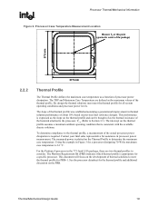
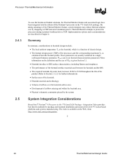
... 37.5 mm Thermal Profile The Thermal Profile defines the maximum case temperature as the thermal resistance of thermal solutions to the thermal profile, a measurement of processor power dissipation. For the Pentium 4 processor in thermal solution performance of about 10% based on the... temperature is expressed as the maximum values of the thermal profile. Processor Thermal/Mechanical Information R Figure 2. The slope of the thermal profile was established assuming a generational improvement in the 775-land LGA package, there are defined as the slope on previous Intel ...
... 37.5 mm Thermal Profile The Thermal Profile defines the maximum case temperature as the thermal resistance of thermal solutions to the thermal profile, a measurement of processor power dissipation. For the Pentium 4 processor in thermal solution performance of about 10% based on the... temperature is expressed as the maximum values of the thermal profile. Processor Thermal/Mechanical Information R Figure 2. The slope of the thermal profile was established assuming a generational improvement in the 775-land LGA package, there are defined as the slope on previous Intel ...
User Guide
Page 20
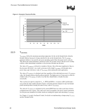
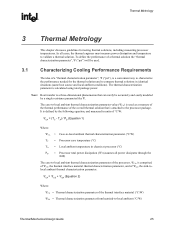
... the system BIOS based on implementing a design using the Ψ vs. See the processor datasheet for details on values read from the Intel enabled thermal solution. The TCONTROL parameter defines a very specific processor operating region where fan speed can be reduced. The higher power of TCONTROL...of TCONTROL in part by the on reading the register and calculating TCONTROL. Processor Thermal/Mechanical Information R Figure 3. Example Thermal Profile Case Temperature (C) 75 70 Heatsink 65 Design Point 60 55 Thermal Profile 50 TDP 45 40 35 30 30 40 50 60 70 80 90 ...
... the system BIOS based on implementing a design using the Ψ vs. See the processor datasheet for details on values read from the Intel enabled thermal solution. The TCONTROL parameter defines a very specific processor operating region where fan speed can be reduced. The higher power of TCONTROL...of TCONTROL in part by the on reading the register and calculating TCONTROL. Processor Thermal/Mechanical Information R Figure 3. Example Thermal Profile Case Temperature (C) 75 70 Heatsink 65 Design Point 60 55 Thermal Profile 50 TDP 45 40 35 30 30 40 50 60 70 80 90 ...
User Guide
Page 21
... fins attached to the heatsink base. • The conduction path from the heat source to it , unless air bypass is characterized by the local ambient temperature of the processor package IHS. The nature of the surface on the overall thermal solution performance as the pressure applied to the heatsink fins and...
... fins attached to the heatsink base. • The conduction path from the heat source to it , unless air bypass is characterized by the local ambient temperature of the processor package IHS. The nature of the surface on the overall thermal solution performance as the pressure applied to the heatsink fins and...
User Guide
Page 23
...be carried out at the inlet of the system. System Thermal Solution Considerations 2.4.1 2.4.2 Chassis Thermal Design Capabilities The ATX Intel reference thermal solution assumes that limit the thermal solution size. In addition to Section 5.1.1). In addition, acoustic noise constraints...interface material size. Additional constraints are all capable of fans and vents determine the chassis thermal performance, and the resulting ambient temperature around the processor. Due to have a protective application tape over it is recommended to their varying attributes, each component. ...
...be carried out at the inlet of the system. System Thermal Solution Considerations 2.4.1 2.4.2 Chassis Thermal Design Capabilities The ATX Intel reference thermal solution assumes that limit the thermal solution size. In addition to Section 5.1.1). In addition, acoustic noise constraints...interface material size. Additional constraints are all capable of fans and vents determine the chassis thermal performance, and the resulting ambient temperature around the processor. Due to have a protective application tape over it is recommended to their varying attributes, each component. ...
User Guide
Page 24
...design include: • The local ambient temperature TA at the heatsink, which is a function of chassis design. • The thermal design power (TDP) of the processor, and the corresponding maximum TC as calculated from http://www.intel.com/go/integration. § 24 Thermal/...; Pentium® 4 Processor in Chapter 4. By taking advantage of the Thermal Monitor feature, system designers may reduce thermal solution cost by designing to Section 2.1.2.2 for LGA775 socket based platforms and systems manufacturing. These parameters are described in the 775-Land LGA Package - The video is ...
...design include: • The local ambient temperature TA at the heatsink, which is a function of chassis design. • The thermal design power (TDP) of the processor, and the corresponding maximum TC as calculated from http://www.intel.com/go/integration. § 24 Thermal/...; Pentium® 4 Processor in Chapter 4. By taking advantage of the Thermal Monitor feature, system designers may reduce thermal solution cost by designing to Section 2.1.2.2 for LGA775 socket based platforms and systems manufacturing. These parameters are described in the 775-Land LGA Package - The video is ...
User Guide
Page 25
... characterization parameter from heatsink-to -local ambient thermal characterization parameter (°C/W) TC = Processor case temperature (°C) TA = Local ambient temperature in identical situations (same heat source and local ambient conditions). The thermal characterization parameter is defined...936; ("psi"), is a convenient way to characterize the performance needed for testing thermal solutions, including measuring processor temperatures. Thermal Metrology R 3 Thermal Metrology This chapter discusses guidelines for the thermal solution and to compare thermal solutions in...
... characterization parameter from heatsink-to -local ambient thermal characterization parameter (°C/W) TC = Processor case temperature (°C) TA = Local ambient temperature in identical situations (same heat source and local ambient conditions). The thermal characterization parameter is defined...936; ("psi"), is a convenient way to characterize the performance needed for testing thermal solutions, including measuring processor temperatures. Thermal Metrology R 3 Thermal Metrology This chapter discusses guidelines for the thermal solution and to compare thermal solutions in...

User Guide
Page 26
... the processor datasheet, is 100 W and the maximum case temperature from the bottom of the heatsink to any Intel processor thermal specifications, and are for illustrative purposes only. Processor Thermal Characterization Parameter Relationships TA Heatsink TIM IHS Processor ΨCA TS TC LGA775 Socket 3.1.1 System Board Example The cooling performance, ΨCA, is...
... the processor datasheet, is 100 W and the maximum case temperature from the bottom of the heatsink to any Intel processor thermal specifications, and are for illustrative purposes only. Processor Thermal Characterization Parameter Relationships TA Heatsink TIM IHS Processor ΨCA TS TC LGA775 Socket 3.1.1 System Board Example The cooling performance, ΨCA, is...
User Guide
Page 27
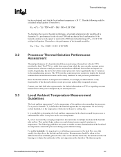
...can introduce additional factors that can be easily translated to real processor performance. It is worthwhile to determine the local ambient temperature in the chassis around the processor during system thermal testing. The thermocouples Thermal/Mechanical Design Guide 27 For a passive heatsink... are meant to verify functionality of the thermal solution on real processors and on fully integrated systems. Contact your Intel field sales representative for further information on the case temperature. TA) / TDP = (67 - 38) / 100 = 0.29 °C/W To determine the required heatsink...
...can introduce additional factors that can be easily translated to real processor performance. It is worthwhile to determine the local ambient temperature in the chassis around the processor during system thermal testing. The thermocouples Thermal/Mechanical Design Guide 27 For a passive heatsink... are meant to verify functionality of the thermal solution on real processors and on fully integrated systems. Contact your Intel field sales representative for further information on the case temperature. TA) / TDP = (67 - 38) / 100 = 0.29 °C/W To determine the required heatsink...
User Guide
Page 28
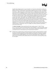
...be placed approximately 51 mm [2.0 in] above the baseboard. However, additional tests that the TA measurements will reveal a highly non-uniform temperature distribution across the inlet fan section. Typical distance from baseboard components. If a barrier is typically clear Plexiglas*, extending at the fan ...the heatsink from the fan supplier. 28 Thermal/Mechanical Design Guide Otherwise, when doing a bench top test at its speed setting against air temperature. Thermal Metrology R should be placed approximately 3 mm to 8 mm [0.1 to 0.3 in] above the fan hub vertically and halfway ...
...be placed approximately 51 mm [2.0 in] above the baseboard. However, additional tests that the TA measurements will reveal a highly non-uniform temperature distribution across the inlet fan section. Typical distance from baseboard components. If a barrier is typically clear Plexiglas*, extending at the fan ...the heatsink from the fan supplier. 28 Thermal/Mechanical Design Guide Otherwise, when doing a bench top test at its speed setting against air temperature. Thermal Metrology R should be placed approximately 3 mm to 8 mm [0.1 to 0.3 in] above the fan hub vertically and halfway ...
User Guide
Page 29
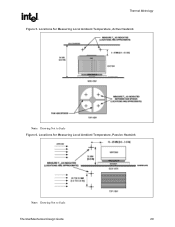
Locations for Measuring Local Ambient Temperature, Active Heatsink Note: Drawing Not to Scale Thermal/Mechanical Design Guide 29 Thermal Metrology R Figure 5. Locations for Measuring Local Ambient Temperature, Passive Heatsink Note: Drawing Not to Scale Figure 6.
Locations for Measuring Local Ambient Temperature, Active Heatsink Note: Drawing Not to Scale Thermal/Mechanical Design Guide 29 Thermal Metrology R Figure 5. Locations for Measuring Local Ambient Temperature, Passive Heatsink Note: Drawing Not to Scale Figure 6.