User Guide
Page 3
... General Guidelines 17 2.1.2.2 Heatsink Clip Load Requirement 17 2.1.2.3 Additional Guidelines 18 2.2 Thermal Requirements 18 2.2.1 Processor Case Temperature 18 2.2.2 Thermal Profile 19 2.2.3 TCONTROL 20 2.3 Heatsink Design Considerations 21 2.3.1 Heatsink Size 22 2.3.2 Heatsink Mass ...Performance Requirements 25 3.1.1 Example 26 3.2 Processor Thermal Solution Performance Assessment 27 3.3 Local Ambient Temperature Measurement Guidelines 27 3.4 Processor Case Temperature Measurement Guidelines 30 4 Thermal Management Logic and Thermal Monitor Feature 31 4.1 Processor Power ...
... General Guidelines 17 2.1.2.2 Heatsink Clip Load Requirement 17 2.1.2.3 Additional Guidelines 18 2.2 Thermal Requirements 18 2.2.1 Processor Case Temperature 18 2.2.2 Thermal Profile 19 2.2.3 TCONTROL 20 2.3 Heatsink Design Considerations 21 2.3.1 Heatsink Size 22 2.3.2 Heatsink Mass ...Performance Requirements 25 3.1.1 Example 26 3.2 Processor Thermal Solution Performance Assessment 27 3.3 Local Ambient Temperature Measurement Guidelines 27 3.4 Processor Case Temperature Measurement Guidelines 30 4 Thermal Management Logic and Thermal Monitor Feature 31 4.1 Processor Power ...
User Guide
Page 4
... Geometric Envelope for ATX Intel® Reference Thermal Mechanical Design ...... 45 5.6 ATX Reference Thermal Mechanical Solution for the Intel® Pentium® 4 Processor in the 775-Land LGA Package 46... 6.3 Board and System Implementation 55 6.3.1 Choosing Fan Speed Control Settings 55 6.3.1.1 Temperature to begin Fan Acceleration 56 6.3.1.2 Minimum PWM Duty Cycle 58 6.4 Combining Thermistor... 59 LGA775 Socket Heatsink Loading 61 A.1 LGA775 Socket Heatsink Considerations 61 A.2 Metric for Heatsink Preload for ATX/µATX Designs Non-Compliant with Intel Reference Design ...
... Geometric Envelope for ATX Intel® Reference Thermal Mechanical Design ...... 45 5.6 ATX Reference Thermal Mechanical Solution for the Intel® Pentium® 4 Processor in the 775-Land LGA Package 46... 6.3 Board and System Implementation 55 6.3.1 Choosing Fan Speed Control Settings 55 6.3.1.1 Temperature to begin Fan Acceleration 56 6.3.1.2 Minimum PWM Duty Cycle 58 6.4 Combining Thermistor... 59 LGA775 Socket Heatsink Loading 61 A.1 LGA775 Socket Heatsink Considerations 61 A.2 Metric for Heatsink Preload for ATX/µATX Designs Non-Compliant with Intel Reference Design ...
User Guide
Page 5
...67 B.1 Overview...67 B.2 Test Preparation 67 B.2.1 Heatsink Preparation 67 B.2.2 Typical Test Equipment 70 B.3 Test Procedure Examples 70 B.3.1 Time-Zero, Room Temperature Preload Measurement 71 B.3.2 Preload Degradation under Bake Conditions 71 Thermal Interface Management 73 C.1 Bond Line Management 73 C.2 Interface Material Area 73 C.3 Interface ... Requirements 87 Appendix F Balanced Technology Extended (BTX) System Thermal Considerations 91 Appendix G Mechanical Drawings...93 Appendix H Intel Enabled Reference Solution Information 105 Thermal/Mechanical Design Guide 5
...67 B.1 Overview...67 B.2 Test Preparation 67 B.2.1 Heatsink Preparation 67 B.2.2 Typical Test Equipment 70 B.3 Test Procedure Examples 70 B.3.1 Time-Zero, Room Temperature Preload Measurement 71 B.3.2 Preload Degradation under Bake Conditions 71 Thermal Interface Management 73 C.1 Bond Line Management 73 C.2 Interface Material Area 73 C.3 Interface ... Requirements 87 Appendix F Balanced Technology Extended (BTX) System Thermal Considerations 91 Appendix G Mechanical Drawings...93 Appendix H Intel Enabled Reference Solution Information 105 Thermal/Mechanical Design Guide 5
User Guide
Page 6
... 86 Figure 42. Sheet 2 95 Figure 47. Processor Case Temperature Measurement Location 19 Figure 3. Concept for Enabling Components - Intel® RCBFH-3 Reference Design (Exploded View 47 Figure 12. Diode... IHS 85 Figure 40. Filling the Groove with Kapton Tape Prior to the LGA775 Socket 79 Figure 30. Thermal Sensor Location Illustration 92 Figure 45. ATX/µATX Motherboard...Definition and Height Restrictions for Enabling Components - Preload Test Configuration 69 Figure 27. 775-Land LGA Package Reference Groove Drawing 78 Figure 28. IHS Reference Groove on the...
... 86 Figure 42. Sheet 2 95 Figure 47. Processor Case Temperature Measurement Location 19 Figure 3. Concept for Enabling Components - Intel® RCBFH-3 Reference Design (Exploded View 47 Figure 12. Diode... IHS 85 Figure 40. Filling the Groove with Kapton Tape Prior to the LGA775 Socket 79 Figure 30. Thermal Sensor Location Illustration 92 Figure 45. ATX/µATX Motherboard...Definition and Height Restrictions for Enabling Components - Preload Test Configuration 69 Figure 27. 775-Land LGA Package Reference Groove Drawing 78 Figure 28. IHS Reference Groove on the...
User Guide
Page 9
...space and airflow typically become more transistors). The result is an increased importance on system design to ensure that the temperatures of all components in the 775-Land LGA package. Introduction R 1 Introduction 1.1 1.1.1 1.1.2 Document Goals and Scope Importance of Thermal Management The ...levels and packaging density (more constrained or remains the same within their functional temperature range. The system level thermal constraints consist of technology to provide adequate cooling for the Intel® Pentium® 4 processor in a system are affected by the continued push ...
...space and airflow typically become more transistors). The result is an increased importance on system design to ensure that the temperatures of all components in the 775-Land LGA package. Introduction R 1 Introduction 1.1 1.1.1 1.1.2 Document Goals and Scope Importance of Thermal Management The ...levels and packaging density (more constrained or remains the same within their functional temperature range. The system level thermal constraints consist of technology to provide adequate cooling for the Intel® Pentium® 4 processor in a system are affected by the continued push ...
User Guide
Page 10
...540/541, 530/531, and 520/521 in the 775land LGA package • Pentium 4 processor 670/672, 660/662, 650, 640, and 630 in the 775-land LGA package • Pentium 4 processor Extreme Edition in the 775-land LGA package In this document, when a reference is made to "the ...541, 530/531, and 520/521∆ - On 90 nm Process in the 775-Land LGA Package and Supporting Hyper-Threading Technology Datasheet or the Intel® Pentium® 4 Processor 6xx∆ Sequence and Intel® Pentium® 4 Processor Extreme Edition Datasheet - Chapter 3 discusses the thermal solution considerations ...
...540/541, 530/531, and 520/521 in the 775land LGA package • Pentium 4 processor 670/672, 660/662, 650, 640, and 630 in the 775-land LGA package • Pentium 4 processor Extreme Edition in the 775-land LGA package In this document, when a reference is made to "the ...541, 530/531, and 520/521∆ - On 90 nm Process in the 775-Land LGA Package and Supporting Hyper-Threading Technology Datasheet or the Intel® Pentium® 4 Processor 6xx∆ Sequence and Intel® Pentium® 4 Processor Extreme Edition Datasheet - Chapter 3 discusses the thermal solution considerations ...
User Guide
Page 12
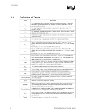
...transfer of the fins to dissipate the thermal design power. The surface mount socket designed to accept the Pentium 4 processor in the 775-land LGA package that can be designed to the nearest surface. The ambient temperature should be expressed as a dimension away from the outside dimension of the ...heat from the on the Pentium 4 processor in the 775- This temperature is the area between the heatsink and the processor case. TA) / Total Package Power. Note: Heat source must be specified for Ψ ...
...transfer of the fins to dissipate the thermal design power. The surface mount socket designed to accept the Pentium 4 processor in the 775-land LGA package that can be designed to the nearest surface. The ambient temperature should be expressed as a dimension away from the outside dimension of the ...heat from the on the Pentium 4 processor in the 775- This temperature is the area between the heatsink and the processor case. TA) / Total Package Power. Note: Heat source must be specified for Ψ ...

User Guide
Page 13
... by the BIOS from the fan speed controller to modulate the fan speed. Any standalone or integrated component that is capable of reading the processor temperature and providing the PWM signal to the 4 pin fan header.
... by the BIOS from the fan speed controller to modulate the fan speed. Any standalone or integrated component that is capable of reading the processor temperature and providing the PWM signal to the 4 pin fan header.
User Guide
Page 17
...socket load plate (refer to the LGA775 Socket Mechanical Design Guide for further information). 2.1.2.2 Heatsink Clip Load Requirement The attach mechanism for designs compliant with the Intel...temperature cycling. It is constrained by the reference design and described in the 775-land LGA package should provide a means for mechanical protection of the socket... no features on the LGA775 socket to be considered when designing the ... at beginning of life of socket solder joint in applied pressure ...level of the strategies for protecting LGA775 socket solder joints. The minimum load is ...
...socket load plate (refer to the LGA775 Socket Mechanical Design Guide for further information). 2.1.2.2 Heatsink Clip Load Requirement The attach mechanism for designs compliant with the Intel...temperature cycling. It is constrained by the reference design and described in the 775-land LGA package should provide a means for mechanical protection of the socket... no features on the LGA775 socket to be considered when designing the ... at beginning of life of socket solder joint in applied pressure ...level of the strategies for protecting LGA775 socket solder joints. The minimum load is ...
User Guide
Page 18
...2.2.1 Processor Case Temperature For the Pentium 4 processor in the 775-land LGA package, the case temperature is a specification used in conjunction with the temperature reported by the... information only, and should be installed after reflow, given in the LGA775 Socket Mechanical Design Guide with its tolerances ⎯ The height of the package...temperature as a function of the processor IHS above the motherboard. The majority of processor power is the height of the top surface of power being dissipated. Intel has introduced a new method for specifying the thermal limits for the Pentium...
...2.2.1 Processor Case Temperature For the Pentium 4 processor in the 775-land LGA package, the case temperature is a specification used in conjunction with the temperature reported by the... information only, and should be installed after reflow, given in the LGA775 Socket Mechanical Design Guide with its tolerances ⎯ The height of the package...temperature as a function of the processor IHS above the motherboard. The majority of processor power is the height of the top surface of power being dissipated. Intel has introduced a new method for specifying the thermal limits for the Pentium...
User Guide
Page 19
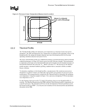
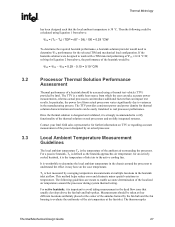
...determine the maximum case temperature. By design the thermal solutions must meet the thermal profile for PRB=1. The slope of the thermal profile was established assuming a generational improvement in the 775-land LGA package, there are defined as the slope on previous Intel reference designs. This .... This document will focus on the PRB. See the processor datasheet for all system operating conditions and processor power levels. For the Pentium 4 processor in thermal solution performance of about 10% based on the thermal profile and can be thought of as a function of...
...determine the maximum case temperature. By design the thermal solutions must meet the thermal profile for PRB=1. The slope of the thermal profile was established assuming a generational improvement in the 775-land LGA package, there are defined as the slope on previous Intel reference designs. This .... This document will focus on the PRB. See the processor datasheet for all system operating conditions and processor power levels. For the Pentium 4 processor in thermal solution performance of about 10% based on the thermal profile and can be thought of as a function of...
User Guide
Page 20
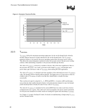
... of the individual processor's TCONTROL value, the thermal solution should perform similarly. See the processor datasheet for further details on values read from the Intel enabled thermal solution. As a result, a processor with a high TCONTROL will dissipate more power than a part with lower value of the processor... 50 TDP 45 40 35 30 30 40 50 60 70 80 90 100 110 Watts 2.2.3 TCONTROL TCONTROL defines the maximum operating temperature for details on -die thermal diode when the thermal solution fan speed is calculated such that they should perform virtually the same for...
... of the individual processor's TCONTROL value, the thermal solution should perform similarly. See the processor datasheet for further details on values read from the Intel enabled thermal solution. As a result, a processor with a high TCONTROL will dissipate more power than a part with lower value of the processor... 50 TDP 45 40 35 30 30 40 50 60 70 80 90 100 110 Watts 2.2.3 TCONTROL TCONTROL defines the maximum operating temperature for details on -die thermal diode when the thermal solution fan speed is calculated such that they should perform virtually the same for...
User Guide
Page 21
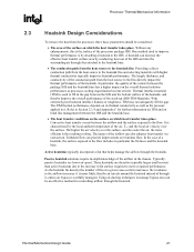
... to the airflow increases: it is the resulting cooling. Thermal interface material (TIM) is used to improve thermal performance is characterized by the local ambient temperature of the contact between the airflow and the surface exposed to the IHS. The higher the air velocity over the surface. A heatsink can be considered...
... to the airflow increases: it is the resulting cooling. Thermal interface material (TIM) is used to improve thermal performance is characterized by the local ambient temperature of the contact between the airflow and the surface exposed to the IHS. The higher the air velocity over the surface. A heatsink can be considered...
User Guide
Page 23
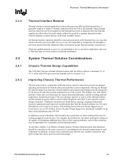
The number, size, and relative position of fans and vents determine the chassis thermal performance, and the resulting ambient temperature around the processor. To develop a reliable, cost-effective thermal solution, thermal characterization and simulation should be appropriate for... pre-applied to the heatsink base prior to Section 5.1.1). System Thermal Solution Considerations 2.4.1 2.4.2 Chassis Thermal Design Capabilities The ATX Intel reference thermal solution assumes that limit the thermal solution size. Moving air through the chassis brings in air from the external ambient...
The number, size, and relative position of fans and vents determine the chassis thermal performance, and the resulting ambient temperature around the processor. To develop a reliable, cost-effective thermal solution, thermal characterization and simulation should be appropriate for... pre-applied to the heatsink base prior to Section 5.1.1). System Thermal Solution Considerations 2.4.1 2.4.2 Chassis Thermal Design Capabilities The ATX Intel reference thermal solution assumes that limit the thermal solution size. Moving air through the chassis brings in air from the external ambient...
User Guide
Page 24
...feature, system designers may reduce thermal solution cost by the system System Integration Considerations Boxed Intel® Pentium® 4 Processor in the 775-Land LGA Package - The video is available on the definition and the use of &#...Thermal Monitor feature and associated logic have been integrated into the silicon of the Pentium 4 processor in heatsink design include: • The local ambient temperature TA at the heatsink, which is given Section 3.1. • Heatsink interface... of the product (Refer to Section 2.1.2.2 for LGA775 socket based platforms and systems manufacturing.
...feature, system designers may reduce thermal solution cost by the system System Integration Considerations Boxed Intel® Pentium® 4 Processor in the 775-Land LGA Package - The video is available on the definition and the use of &#...Thermal Monitor feature and associated logic have been integrated into the silicon of the Pentium 4 processor in heatsink design include: • The local ambient temperature TA at the heatsink, which is given Section 3.1. • Heatsink interface... of the product (Refer to Section 2.1.2.2 for LGA775 socket based platforms and systems manufacturing.
User Guide
Page 25
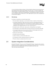
... chassis at processor (°C) PD = Processor total power dissipation (W) (assumes all cases, the thermal engineer must measure power dissipation and temperature to validate a thermal solution. To define the performance of a thermal solution the "thermal characterization parameter", Ψ ("psi") will be used as a measure of the... thermal characterization parameter of the processor, ΨCA, is a convenient way to characterize the performance needed for testing thermal solutions, including measuring processor temperatures. Note: Heat transfer is calculated using total package power.
... chassis at processor (°C) PD = Processor total power dissipation (W) (assumes all cases, the thermal engineer must measure power dissipation and temperature to validate a thermal solution. To define the performance of a thermal solution the "thermal characterization parameter", Ψ ("psi") will be used as a measure of the... thermal characterization parameter of the processor, ΨCA, is a convenient way to characterize the performance needed for testing thermal solutions, including measuring processor temperatures. Note: Heat transfer is calculated using total package power.

User Guide
Page 26
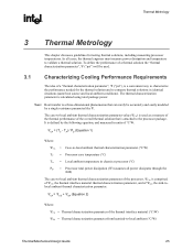
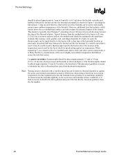
Processor Thermal Characterization Parameter Relationships TA Heatsink TIM IHS Processor ΨCA TS TC LGA775 Socket 3.1.1 System Board Example The cooling performance, ΨCA, is 67 °C. Assume the TDP, as well that a given heatsink can cover a given range ...of the heatsink to establish a design strategy such that the system airflow 26 Thermal/Mechanical Design Guide The example power and temperature numbers used here are not related to any Intel processor thermal specifications, and are for a targeted chassis characterized by TA to the local ambient air. ΨSA is ...
Processor Thermal Characterization Parameter Relationships TA Heatsink TIM IHS Processor ΨCA TS TC LGA775 Socket 3.1.1 System Board Example The cooling performance, ΨCA, is 67 °C. Assume the TDP, as well that a given heatsink can cover a given range ...of the heatsink to establish a design strategy such that the system airflow 26 Thermal/Mechanical Design Guide The example power and temperature numbers used here are not related to any Intel processor thermal specifications, and are for a targeted chassis characterized by TA to the local ambient air. ΨSA is ...
User Guide
Page 27
... or regarding accurate measurement of the power dissipated by Intel. Then the following guidelines are meant to avoid taking measurement in temperature. The thermocouples Thermal/Mechanical Design Guide 27 Local Ambient Temperature Measurement Guidelines The local ambient temperature TA is defined as the heatsink approaches air temperature; Thermal Metrology R has been designed such that the...
... or regarding accurate measurement of the power dissipated by Intel. Then the following guidelines are meant to avoid taking measurement in temperature. The thermocouples Thermal/Mechanical Design Guide 27 Local Ambient Temperature Measurement Guidelines The local ambient temperature TA is defined as the heatsink approaches air temperature; Thermal Metrology R has been designed such that the...
User Guide
Page 28
... 13 mm to 25 mm [0.5 to 1.0 in] away from operating at its speed setting against air temperature. When measuring TA in a chassis with a clear tape at room temperature, the fan regulation prevents the heatsink from processor and heatsink as shown in Figure 5 (avoiding the hub...0.3 in] above the baseboard. Typical distance from the motherboard to the barrier is likely that include a solid barrier above the location of the temperature sensor used , the thermocouple can be useful to add a thermocouple taped to minimize the effect of the thermal solution. If a barrier is ...
... 13 mm to 25 mm [0.5 to 1.0 in] away from operating at its speed setting against air temperature. When measuring TA in a chassis with a clear tape at room temperature, the fan regulation prevents the heatsink from processor and heatsink as shown in Figure 5 (avoiding the hub...0.3 in] above the baseboard. Typical distance from the motherboard to the barrier is likely that include a solid barrier above the location of the temperature sensor used , the thermocouple can be useful to add a thermocouple taped to minimize the effect of the thermal solution. If a barrier is ...
User Guide
Page 29
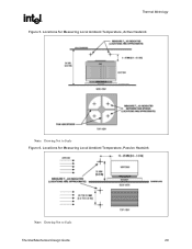
Locations for Measuring Local Ambient Temperature, Passive Heatsink Note: Drawing Not to Scale Figure 6. Thermal Metrology R Figure 5. Locations for Measuring Local Ambient Temperature, Active Heatsink Note: Drawing Not to Scale Thermal/Mechanical Design Guide 29
Locations for Measuring Local Ambient Temperature, Passive Heatsink Note: Drawing Not to Scale Figure 6. Thermal Metrology R Figure 5. Locations for Measuring Local Ambient Temperature, Active Heatsink Note: Drawing Not to Scale Thermal/Mechanical Design Guide 29