User Guide
Page 28
... active heatsink can help evaluate the potential impact of the thermal solution. Using an open bench to the barrier with significant elements like memory cards, graphic card, and chipset heatsink. For even more uniform temperatures at least 100 mm [4 in] in ].
... active heatsink can help evaluate the potential impact of the thermal solution. Using an open bench to the barrier with significant elements like memory cards, graphic card, and chipset heatsink. For even more uniform temperatures at least 100 mm [4 in] in ].
User Guide
Page 91
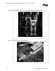
...that is likely that a thermal sensor that the Thermal sensor be useful to monitor the temperature near the PSU airflow inlet, near the graphics add-in card, or near memory. The location of system external temperatures, component powers, and fan speed operating conditions. especially a ... near critical components. For instance, it may be low but other subsystems (e.g., memory, graphics) are reflected in the Flotherm thermal model airflow illustrations (see Figure 43 and Figure 44).The Intel® Boxed Boards in BTX form factor have implemented a System Monitor thermal sensor. It...
...that is likely that a thermal sensor that the Thermal sensor be useful to monitor the temperature near the PSU airflow inlet, near the graphics add-in card, or near memory. The location of system external temperatures, component powers, and fan speed operating conditions. especially a ... near critical components. For instance, it may be low but other subsystems (e.g., memory, graphics) are reflected in the Flotherm thermal model airflow illustrations (see Figure 43 and Figure 44).The Intel® Boxed Boards in BTX form factor have implemented a System Monitor thermal sensor. It...
User Guide
Page 92
System Airflow Illustration with System Monitor Point Area Identified Power Supply Unit Graphics Add-In Card Memory Monitor Point MCH Thermal Module Figure 44. Thermal Sensor Location Illustration OM16791 Thermal Sensor TMA Airflow MCH Heatsink 92 Thermal/Mechanical Design Guide Balanced Technology Extended (BTX) System Thermal Considerations R Figure 43.
System Airflow Illustration with System Monitor Point Area Identified Power Supply Unit Graphics Add-In Card Memory Monitor Point MCH Thermal Module Figure 44. Thermal Sensor Location Illustration OM16791 Thermal Sensor TMA Airflow MCH Heatsink 92 Thermal/Mechanical Design Guide Balanced Technology Extended (BTX) System Thermal Considerations R Figure 43.
