Instruction Manual
Page 2
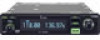
..., Russia and/or other countries. Icom, Icom Inc. i Equipment damage may occur. porated (Japan) in - The IC-A210 is a registered trademark of Microsoft Corporation in ❍ Intercom function The IC-A210 has a built-in the IC-A210. The IC-A210 has adjustable audio level and squelch control...simultaneously. In addition, the auto dimmer function adjusts the display for the IC-A210. The dualwatch function allows you to talk with an airport frequency database, the IC-A210 will instantly tune in most airplanes or vehicles. When connected to this ...
..., Russia and/or other countries. Icom, Icom Inc. i Equipment damage may occur. porated (Japan) in - The IC-A210 is a registered trademark of Microsoft Corporation in ❍ Intercom function The IC-A210 has a built-in the IC-A210. The IC-A210 has adjustable audio level and squelch control...simultaneously. In addition, the auto dimmer function adjusts the display for the IC-A210. The dualwatch function allows you to talk with an airport frequency database, the IC-A210 will instantly tune in most airplanes or vehicles. When connected to this ...
Instruction Manual
Page 32
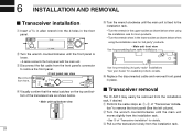
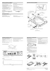
... socket as shown below when using the installation rack for 3rd party* products. ¥ Main unit front view Use for pre-existing Icom radio installations Use for pre-existing 3rd party radio* installations *Ask your dealer for details. e Disconnect the flat cable from the... r Visually confirm that the metal catches on the top and bottom of "Transceiver installa- 6 INSTALLATION AND REMOVAL I Transceiver removal The IC-A210 may easily be removed from the installation rack. • See t of "Transceiver installation" for available products details. DUAL EC VOL RCL MEM ...
... socket as shown below when using the installation rack for 3rd party* products. ¥ Main unit front view Use for pre-existing Icom radio installations Use for pre-existing 3rd party radio* installations *Ask your dealer for details. e Disconnect the flat cable from the... r Visually confirm that the metal catches on the top and bottom of "Transceiver installa- 6 INSTALLATION AND REMOVAL I Transceiver removal The IC-A210 may easily be removed from the installation rack. • See t of "Transceiver installation" for available products details. DUAL EC VOL RCL MEM ...
Installation Guide
Page 1
...guide and transceiver's instruction manual carefully before attempting to pin 9 of #18 AWG wires for purchasing the IC-A210/A210E VHF AIR BAND TRANSCEIVER with Icom's state of the aircraft may be installed in the DC power line in your aircraft, etc., with the ...15 In Microphone 2 + (600 Ω) *Ground to +131˚F). Install the IC-A210/A210E according to the transceiver with BNC connector (50 Ω). y Mount the IC-A210/A210E into your aircraft, wiring for the IC-A210/A210E. IC-A210 MB-113 t Attach the MB-113 to the following procedure. Refer to the power ...
...guide and transceiver's instruction manual carefully before attempting to pin 9 of #18 AWG wires for purchasing the IC-A210/A210E VHF AIR BAND TRANSCEIVER with Icom's state of the aircraft may be installed in the DC power line in your aircraft, etc., with the ...15 In Microphone 2 + (600 Ω) *Ground to +131˚F). Install the IC-A210/A210E according to the transceiver with BNC connector (50 Ω). y Mount the IC-A210/A210E into your aircraft, wiring for the IC-A210/A210E. IC-A210 MB-113 t Attach the MB-113 to the following procedure. Refer to the power ...
Installation Guide
Page 2
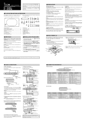
... mounting bracket. iA210 160 mm; 6 5/16″ D Template Cut out dimensions for the front panel as in Japan © 2007 Icom Inc. Main unit front view Use when installing with the en- e Slowly pull the transceiver out from each wire for the contact terminal....figure below. e Insert the stripped conductor unit the insulation is obtained. r Clip the conductor tab until a click is obtained. D Transceiver removal The IC-A210/A210E is fully in, pull the lead using a 3⁄32″ (2.381mm) allen wrench, then disconnect the flat cable from the front panel. (Fig....
... mounting bracket. iA210 160 mm; 6 5/16″ D Template Cut out dimensions for the front panel as in Japan © 2007 Icom Inc. Main unit front view Use when installing with the en- e Slowly pull the transceiver out from each wire for the contact terminal....figure below. e Insert the stripped conductor unit the insulation is obtained. r Clip the conductor tab until a click is obtained. D Transceiver removal The IC-A210/A210E is fully in, pull the lead using a 3⁄32″ (2.381mm) allen wrench, then disconnect the flat cable from the front panel. (Fig....


