
Instruction Manual
Page 1
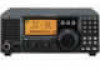
INSTRUCTION MANUAL HF TRANSCEIVER i78 This device complies with Part 15 of the FCC rules. Operation is subject to the following two conditions: (1) This device may not cause harmful interference, and (2) this device must accept any interference received, including interference that may cause undesired operation.
INSTRUCTION MANUAL HF TRANSCEIVER i78 This device complies with Part 15 of the FCC rules. Operation is subject to the following two conditions: (1) This device may not cause harmful interference, and (2) this device must accept any interference received, including interference that may cause undesired operation.

Instruction Manual
Page 2
...;C (+140°F). This will avoid possible damage to the [DC13.8V] jack on the transceiver rear panel. SAVE THIS INSTRUCTION MANUAL. The heatsink will be damaged. Use Icom microphones only (supplied or optional). EXPLICIT DEFINITIONS WORD DEFINITION R WARNING Personal injury, fire...DC, such as possible from the magnetic navigation compass to the IC-78 may damage the transceiver. AVOID placing the transceiver against walls or putting anything on the rear panel of the transceiver. When the transceiver power is ON and your vehicle's engine is OFF, the vehicle...
...;C (+140°F). This will avoid possible damage to the [DC13.8V] jack on the transceiver rear panel. SAVE THIS INSTRUCTION MANUAL. The heatsink will be damaged. Use Icom microphones only (supplied or optional). EXPLICIT DEFINITIONS WORD DEFINITION R WARNING Personal injury, fire...DC, such as possible from the magnetic navigation compass to the IC-78 may damage the transceiver. AVOID placing the transceiver against walls or putting anything on the rear panel of the transceiver. When the transceiver power is ON and your vehicle's engine is OFF, the vehicle...
Instruction Manual
Page 3
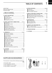
...FEATURES 34- 36 s Instruction 34 s VFO operation 34 s 2-Tone alarm operation 36 7 INSTALLATION AND CONNECTIONS ........ 37- 38 s Opening the transceiver's case 37 s Optional bracket and carrying handle 37 s CR-338 HIGH STABILITY CRYSTAL UNIT ......... 38 s Optional IF filters 38 8 ... Resetting the CPU 40 9 REMOTE JACK INFORMATION 41- 42 s CI-V remote control 41 s Data cloning between transceivers 42 10 SPECIFICATIONS 43 12 OPTIONS 44- 45 SUPPLIED ACCESSORIES The transceiver comes with the following accessories. q DC power cable 1 w Hand microphone (HM-36 1 e Fuse (FGB ...
...FEATURES 34- 36 s Instruction 34 s VFO operation 34 s 2-Tone alarm operation 36 7 INSTALLATION AND CONNECTIONS ........ 37- 38 s Opening the transceiver's case 37 s Optional bracket and carrying handle 37 s CR-338 HIGH STABILITY CRYSTAL UNIT ......... 38 s Optional IF filters 38 8 ... Resetting the CPU 40 9 REMOTE JACK INFORMATION 41- 42 s CI-V remote control 41 s Data cloning between transceivers 42 10 SPECIFICATIONS 43 12 OPTIONS 44- 45 SUPPLIED ACCESSORIES The transceiver comes with the following accessories. q DC power cable 1 w Hand microphone (HM-36 1 e Fuse (FGB ...
Instruction Manual
Page 7
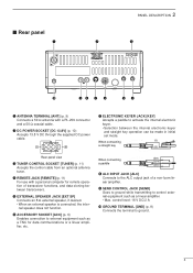
.... When connecting a paddle (dot) (com) (dash) i ALC INPUT JACK [ALC] Connects to activate the internal electronic keyer. •Selection between transceivers. control level: 16 V DC/2 A !0 GROUND TERMINAL [GND] (p. 9) Connects the terminal to control external equipment such as a TNC for remote operation of a... non-Icom linear amplifier. w DC POWER SOCKET [DC 13.8V] (p. 10) Accepts 13.8 V DC through the supplied DC power cable. r REMOTE JACK ...
.... When connecting a paddle (dot) (com) (dash) i ALC INPUT JACK [ALC] Connects to activate the internal electronic keyer. •Selection between transceivers. control level: 16 V DC/2 A !0 GROUND TERMINAL [GND] (p. 9) Connects the terminal to control external equipment such as a TNC for remote operation of a... non-Icom linear amplifier. w DC POWER SOCKET [DC 13.8V] (p. 10) Accepts 13.8 V DC through the supplied DC power cable. r REMOTE JACK ...

Instruction Manual
Page 10
... cable. Of course, the transmission line should be increased out-of-range. When the SWR is higher than approx. 2.0:1, the transceiver's power drops to one of critical importance, along with the IC-78, see 'Supplied accessories' on and solder it. For a description and a diagram of accessory equipment included with output power and sensitivity...
... cable. Of course, the transmission line should be increased out-of-range. When the SWR is higher than approx. 2.0:1, the transceiver's power drops to one of critical importance, along with the IC-78, see 'Supplied accessories' on and solder it. For a description and a diagram of accessory equipment included with output power and sensitivity...
Instruction Manual
Page 13
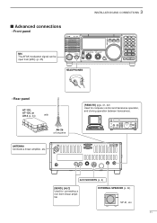
ACC SOCKETS (p. 6) [SEND], [ALC] Used for computer control and transceive operation, and cloning operation between transceivers. EXTERNAL SPEAKER (p. 44) SP-21, etc. 11 s Advanced connections • Front panel 3 INSTALLATION AND CONNECTIONS MIC The AFSK modulation signal can be input from [MIC]. (p. 25) PWR HEADPHONES • Rear panel AT-120, AT-130, or AH-4 (p. 44) with AH-2b or long wire ANTENNA Connects a linear amplifier, etc. [REMOTE] (pgs. 41, 42) Used for connecting a non-Icom linear amplifier.
ACC SOCKETS (p. 6) [SEND], [ALC] Used for computer control and transceive operation, and cloning operation between transceivers. EXTERNAL SPEAKER (p. 44) SP-21, etc. 11 s Advanced connections • Front panel 3 INSTALLATION AND CONNECTIONS MIC The AFSK modulation signal can be input from [MIC]. (p. 25) PWR HEADPHONES • Rear panel AT-120, AT-130, or AH-4 (p. 44) with AH-2b or long wire ANTENNA Connects a linear amplifier, etc. [REMOTE] (pgs. 41, 42) Used for connecting a non-Icom linear amplifier.

Instruction Manual
Page 15
... changing a small number of the desired channel number using the keypad (0 to suit your needs. A total of 3 ways of channel selection. 4 OPERATION s Selecting a channel The transceiver has 99 memory channels.
... changing a small number of the desired channel number using the keypad (0 to suit your needs. A total of 3 ways of channel selection. 4 OPERATION s Selecting a channel The transceiver has 99 memory channels.

Instruction Manual
Page 19
... Push [∫ UP]/[√ DN] one or more times to select "AN VOX" u If the receive audio from the speaker switches the transceiver to transmit during receive, adjust the "ANTI-VOX" to select "VOX Delay" t While speaking into your signal. ALC zone Adjust [MIC GAIN... Transmission) function switches between transmit and receive with the channel selector, until the trans- while operating. 4 OPERATION ï Microphone compressor IC-78 has a built-in SSB mode and is especially useful when the receiving station is transmitting. This function provides an opportunity to 50. ...
... Push [∫ UP]/[√ DN] one or more times to select "AN VOX" u If the receive audio from the speaker switches the transceiver to transmit during receive, adjust the "ANTI-VOX" to select "VOX Delay" t While speaking into your signal. ALC zone Adjust [MIC GAIN... Transmission) function switches between transmit and receive with the channel selector, until the trans- while operating. 4 OPERATION ï Microphone compressor IC-78 has a built-in SSB mode and is especially useful when the receiving station is transmitting. This function provides an opportunity to 50. ...

Instruction Manual
Page 20
...) • When the connected wire cannot be damaged. TUNER OPERATION Tuning is connected to re-tune the antenna before tuning may damage the transceiver. u Push [PWR] to select [TUNER]. Blinks: While tuning Appears: Tune is completed Disappears: Tune is not completed (When AT-120..." goes out, the antenna tuner is connected, the indicator disappears even when tuned completely.) the transceiver directly. 4 OPERATION ï Optional AT-120/AT-130/AH-4 operation The AT-120, AT-130 or AH-4 matches the IC-78 to start tuning. • " " blinks and "CW" appears while tuning. [TUNER] ...
...) • When the connected wire cannot be damaged. TUNER OPERATION Tuning is connected to re-tune the antenna before tuning may damage the transceiver. u Push [PWR] to select [TUNER]. Blinks: While tuning Appears: Tune is completed Disappears: Tune is not completed (When AT-120..." goes out, the antenna tuner is connected, the indicator disappears even when tuned completely.) the transceiver directly. 4 OPERATION ï Optional AT-120/AT-130/AH-4 operation The AT-120, AT-130 or AH-4 matches the IC-78 to start tuning. • " " blinks and "CW" appears while tuning. [TUNER] ...

Instruction Manual
Page 34
... bytes. • This item MUST be set to "on . • CI-V 731 mode When connecting the IC-78 to the IC-735 for each CI-V transceiver has its own Icom standard address in the range 01H to 99. Four selections are available. • no . • Number of... maximum memory channels Sets number of connected transceivers (or receivers) and vice versa. The default is 62. • CI-V Transceive Transceive operation is on " when operating the transceiver with the IC-78 connected to other Icom HF transceivers or receivers. The default is n (normal). • Tuner type...
... bytes. • This item MUST be set to "on . • CI-V 731 mode When connecting the IC-78 to the IC-735 for each CI-V transceiver has its own Icom standard address in the range 01H to 99. Four selections are available. • no . • Number of... maximum memory channels Sets number of connected transceivers (or receivers) and vice versa. The default is 62. • CI-V Transceive Transceive operation is on " when operating the transceiver with the IC-78 connected to other Icom HF transceivers or receivers. The default is n (normal). • Tuner type...

Instruction Manual
Page 36
... To enter VFO mode, push [FC] for 1 sec. • VFO indicator appears. • In the VFO mode, channel comment cannot be indicated. [FC] D Tuning The transceiver has several ways of tuning for temporal operation as follows; • Tuning with the channel selector By rotating the channel selector, operating frequency changes in...
... To enter VFO mode, push [FC] for 1 sec. • VFO indicator appears. • In the VFO mode, channel comment cannot be indicated. [FC] D Tuning The transceiver has several ways of tuning for temporal operation as follows; • Tuning with the channel selector By rotating the channel selector, operating frequency changes in...

Instruction Manual
Page 39
... an optional unit or adjust an internal unit, etc. Select an area to mount the transceiver keeping in a vehicle, etc. Otherwise, there is approx. 3.80kg. CAUTION: DISCONNECT the DC power cable from the IC-78 before performing any work on a wall, in mind that the weight of the... transceiver is danger of the transceiver, then remove the bottom cover. Attach the MB-23 CARRYING HANDLE with the supplied rubber feet ...
... an optional unit or adjust an internal unit, etc. Select an area to mount the transceiver keeping in a vehicle, etc. Otherwise, there is approx. 3.80kg. CAUTION: DISCONNECT the DC power cable from the IC-78 before performing any work on a wall, in mind that the weight of the... transceiver is danger of the transceiver, then remove the bottom cover. Attach the MB-23 CARRYING HANDLE with the supplied rubber feet ...

Instruction Manual
Page 40
... Tr-clamper t Solder the 4 leads. 7 INSTALLATION AND CONNECTIONS s CR-338 HIGH STABILITY CRYSTAL UNIT By installing the CR-338, the total frequency stability of the transceiver will not function properly. 38 r Remove the supplied internal crystal and replace with the CR-338. You can install 1 filter for the...
... Tr-clamper t Solder the 4 leads. 7 INSTALLATION AND CONNECTIONS s CR-338 HIGH STABILITY CRYSTAL UNIT By installing the CR-338, the total frequency stability of the transceiver will not function properly. 38 r Remove the supplied internal crystal and replace with the CR-338. You can install 1 filter for the...
Instruction Manual
Page 41
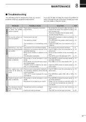
...[ATT] to turn the lock function p. 14 OFF. • Push [SET] to exit the quick set mode is selected. • Push [LOCK] to your nearest Icom Dealer or Service Center. p. 19 Received audio is un- • Wrong type of mode (emission) is se- • Push [MODE] to the antenna connector. ...the noise blanker OFF. p. 18 are not able to select the proper operat- usual. If you correct problems which opens p. 15 the squelch. • The transceiver is se- • Push [MODE] to locate the cause of a problem or solve it through the use of an external unit, p. 5 tion. POWER ...
...[ATT] to turn the lock function p. 14 OFF. • Push [SET] to exit the quick set mode is selected. • Push [LOCK] to your nearest Icom Dealer or Service Center. p. 19 Received audio is un- • Wrong type of mode (emission) is se- • Push [MODE] to the antenna connector. ...the noise blanker OFF. p. 18 are not able to select the proper operat- usual. If you correct problems which opens p. 15 the squelch. • The transceiver is se- • Push [MODE] to locate the cause of a problem or solve it through the use of an external unit, p. 5 tion. POWER ...

Instruction Manual
Page 42
... to their defaults. e Replace the top cover. q Remove the top cover as shown on p. 48 w Replace the circuitry fuse as follows: q Make sure transceiver power is reset. 40 The IC-78 has 2 types of the problem, and replace the damaged fuse with a new, rated fuse. w While pushing [UP Y] and [Z DN], push [PWR] to...
... to their defaults. e Replace the top cover. q Remove the top cover as shown on p. 48 w Replace the circuitry fuse as follows: q Make sure transceiver power is reset. 40 The IC-78 has 2 types of the problem, and replace the damaged fuse with a new, rated fuse. w While pushing [UP Y] and [Z DN], push [PWR] to...

Instruction Manual
Page 43
... to a personal computer equipped with an RS-232C port. Up to 4 Icom CI-V transceivers or receivers can be connected through an optional CT-17 CI-V LEVEL CONVERTER to command numbers. The Icom Communications Interface-V (CI-V) controls the following data formats. CONTROLLER TO IC-78 q wert y u FE FE 62 E0 Cn Sc Data area FD 9-15...
... to a personal computer equipped with an RS-232C port. Up to 4 Icom CI-V transceivers or receivers can be connected through an optional CT-17 CI-V LEVEL CONVERTER to command numbers. The Icom Communications Interface-V (CI-V) controls the following data formats. CONTROLLER TO IC-78 q wert y u FE FE 62 E0 Cn Sc Data area FD 9-15...

Instruction Manual
Page 44
... level PREAMP Noise blanker Microphone compressor Read ID s Data cloning between two IC-78's (master and sub) [REMOTE] jack. Master transceiver indicates "M". y Turn power OFF Daughter transceiver indication 42 This function is useful when exactly the same setting of the master IC-78 to other IC-78. 9 CONTROL COMMAND • Command table Command 00 01 02 03 04...
... level PREAMP Noise blanker Microphone compressor Read ID s Data cloning between two IC-78's (master and sub) [REMOTE] jack. Master transceiver indicates "M". y Turn power OFF Daughter transceiver indication 42 This function is useful when exactly the same setting of the master IC-78 to other IC-78. 9 CONTROL COMMAND • Command table Command 00 01 02 03 04...
Instruction Manual
Page 46
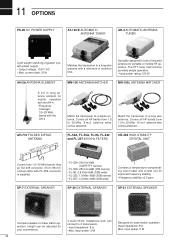
...ANTENNA MATCHER A 2.5 m long antenna element for mobile operation with the AH-4. • Frequency coverage: 3.5-28 MHz bands with the AH-4 Match the transceiver to tune a long wire antenna for your convenience. 4 audio filters; Input impedance: 8 Ω Max. Covers all HF bands from 1.5 to 30... FL-257 455 KHz FILTERS CR-338 HIGH-STABILITY CRYSTAL UNIT Covers from 1.5 to 2 transceivers. • Input impedance: 8 Ω • Max. Specially designed to a dipole antenna. Match the transceiver to a long wire antenna with PL-259 connector is supplied. • FL-52A: 500...
...ANTENNA MATCHER A 2.5 m long antenna element for mobile operation with the AH-4. • Frequency coverage: 3.5-28 MHz bands with the AH-4 Match the transceiver to tune a long wire antenna for your convenience. 4 audio filters; Input impedance: 8 Ω Max. Covers all HF bands from 1.5 to 30... FL-257 455 KHz FILTERS CR-338 HIGH-STABILITY CRYSTAL UNIT Covers from 1.5 to 2 transceivers. • Input impedance: 8 Ω • Max. Specially designed to a dipole antenna. Match the transceiver to a long wire antenna with PL-259 connector is supplied. • FL-52A: 500...
Instruction Manual
Page 47
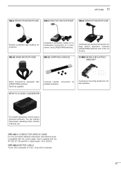
HM-36 HAND MICROPHONE MB-23 CARRYING HANDLE IC-MB5 MOBILE MOUNTING BRACKET Hand microphone equipped with the AT-120, AT-130 and AH-4. OPC-420 4-CONDUCTOR SHIELD CABLE For the connection between transceiver and antenna tuner. Cable length: 10 m (32.8 ft) OPC-599 ADAPTER CABLE 13-pin, ACC ... [UP]/[DOWN] switches and a low cut function. Has [UP]/[DOWN] switches. CT-17 CI-V LEVEL CONVERTER For remote transceiver control using a personal computer. Same as supplied. OPTIONS 11 SM-6 DESKTOP MICROPHONE SM-8 DESKTOP MICROPHONE SM-20 DESKTOP MICROPHONE Electret condenser-...
HM-36 HAND MICROPHONE MB-23 CARRYING HANDLE IC-MB5 MOBILE MOUNTING BRACKET Hand microphone equipped with the AT-120, AT-130 and AH-4. OPC-420 4-CONDUCTOR SHIELD CABLE For the connection between transceiver and antenna tuner. Cable length: 10 m (32.8 ft) OPC-599 ADAPTER CABLE 13-pin, ACC ... [UP]/[DOWN] switches and a low cut function. Has [UP]/[DOWN] switches. CT-17 CI-V LEVEL CONVERTER For remote transceiver control using a personal computer. Same as supplied. OPTIONS 11 SM-6 DESKTOP MICROPHONE SM-8 DESKTOP MICROPHONE SM-20 DESKTOP MICROPHONE Electret condenser-...