Installation Guide
Page 3
CONTENTS NetAXS™ NX4S1 Installation 1.0 Notices ...1 1.1 Warnings and Cautions 1 1.2 Product Liability, Mutual Indemnification 2 1.3 Limited Warranty...2 1.4 Federal Communications Commission 3 1.5 Industry ...Installation...9 4.1 Cabinet Mounting ...10 4.2 Reader Wiring...14 4.3 Supervised Input Wiring 14 4.4 NX4S1 Control Output Wiring 16 4.5 Communications ...16 RS-232 Communications 16 RS-485 Communications 18 Ethernet TCP/IP Communications 19 4.6 DIP Switch Settings ...21 4.7 Jumper Settings...23 4.8 Downstream I/O...23 NetAXS Access Control Unit NX4S1 Installation Guide...
CONTENTS NetAXS™ NX4S1 Installation 1.0 Notices ...1 1.1 Warnings and Cautions 1 1.2 Product Liability, Mutual Indemnification 2 1.3 Limited Warranty...2 1.4 Federal Communications Commission 3 1.5 Industry ...Installation...9 4.1 Cabinet Mounting ...10 4.2 Reader Wiring...14 4.3 Supervised Input Wiring 14 4.4 NX4S1 Control Output Wiring 16 4.5 Communications ...16 RS-232 Communications 16 RS-485 Communications 18 Ethernet TCP/IP Communications 19 4.6 DIP Switch Settings ...21 4.7 Jumper Settings...23 4.8 Downstream I/O...23 NetAXS Access Control Unit NX4S1 Installation Guide...
Installation Guide
Page 5
... Tamper Inputs 60 A.4.4 Door Egress Inputs...60 A.4.5 Door Status Inputs...61 A.4.6 ACFAIL and Panel Tamper Inputs 61 A.4.7 Additional Generic Outputs 62 NetAXS Access Control Unit NX4S1 Installation Guide, Document 800-00008, Revision A v
... Tamper Inputs 60 A.4.4 Door Egress Inputs...60 A.4.5 Door Status Inputs...61 A.4.6 ACFAIL and Panel Tamper Inputs 61 A.4.7 Additional Generic Outputs 62 NetAXS Access Control Unit NX4S1 Installation Guide, Document 800-00008, Revision A v
Installation Guide
Page 7
LIST OF FIGURES Figure 1: NX4S1 Panel Components 6 Figure 2: NetAXS™ NX4S1 Panel Cabinet, Front View 10 Figure 3: NetAXS™ NX4S1 Panel Cabinet, Top View 11 Figure 4: NetAXS™ NX4S1 Panel Cabinet, Bottom View 11 Figure 5: NetAXS™ Panel Cabinet, Left View 12 Figure 6: NetAXS™ NX4S1Panel Cabinet, Right View...: NetAXS™/NetAXS™ Access Controller Panel Connection Detail ......... 41 Figure 32: System, Relay and Power LEDs 42 Figure 33: NX4S1 Panel Wiring Diagram 47 NetAXS Access Control Unit NX4S1 Installation Guide, Document 800-00008, Revision A vii
LIST OF FIGURES Figure 1: NX4S1 Panel Components 6 Figure 2: NetAXS™ NX4S1 Panel Cabinet, Front View 10 Figure 3: NetAXS™ NX4S1 Panel Cabinet, Top View 11 Figure 4: NetAXS™ NX4S1 Panel Cabinet, Bottom View 11 Figure 5: NetAXS™ Panel Cabinet, Left View 12 Figure 6: NetAXS™ NX4S1Panel Cabinet, Right View...: NetAXS™/NetAXS™ Access Controller Panel Connection Detail ......... 41 Figure 32: System, Relay and Power LEDs 42 Figure 33: NX4S1 Panel Wiring Diagram 47 NetAXS Access Control Unit NX4S1 Installation Guide, Document 800-00008, Revision A vii
Installation Guide
Page 9
LIST OF TABLES Table 1 Reader Wiring ...14 Table 2 Default Supervised Input Assignments 14 Table 3 DIP Switch Settings ...22 Table 4 MIRO 32/0 DIP Switch and Jumper Settings 23 Table 5 LED Status ...43 Table 6 Communications and Wiring 46 Table 7 Reader Wiring ...46 Table 8 Troubleshooting Problems and Solutions 48 NetAXS Access Control Unit NX4S1 Installation Guide, Document 800-00008, Revision A ix
LIST OF TABLES Table 1 Reader Wiring ...14 Table 2 Default Supervised Input Assignments 14 Table 3 DIP Switch Settings ...22 Table 4 MIRO 32/0 DIP Switch and Jumper Settings 23 Table 5 LED Status ...43 Table 6 Communications and Wiring 46 Table 7 Reader Wiring ...46 Table 8 Troubleshooting Problems and Solutions 48 NetAXS Access Control Unit NX4S1 Installation Guide, Document 800-00008, Revision A ix
Installation Guide
Page 11
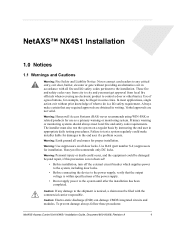
... instructing the end user in accordance with the commercial carrier responsible. To prevent damage always follow these procedures: NetAXS Access Control Unit NX4S1 Installation Guide, Document 800-00008, Revision A 1 These fire and safety codes vary from city to city and you must also test the ... circuits and modules. Warning: Earth ground all fire and life safety codes pertinent to the installation. Always make installer liable for damages to the end user if a problem occurs. Honeywell recommends only DC locks. Use of what to do is within specifications of the power supply...
... instructing the end user in accordance with the commercial carrier responsible. To prevent damage always follow these procedures: NetAXS Access Control Unit NX4S1 Installation Guide, Document 800-00008, Revision A 1 These fire and safety codes vary from city to city and you must also test the ... circuits and modules. Warning: Earth ground all fire and life safety codes pertinent to the installation. Always make installer liable for damages to the end user if a problem occurs. Honeywell recommends only DC locks. Use of what to do is within specifications of the power supply...

Installation Guide
Page 13
...authority to provide reasonable protection against harmful interference in a residential installation. NetAXS Access Control Unit NX4S1 Installation Guide, Document 800-00008, Revision A 3 This equipment generates, uses, and can be used in a particular installation. If this equipment does cause harmful interference to radio or ...LOSS OF PROFITS, LOSS OF USE, INCIDENTAL, CONSEQUENTIAL OR SPECIAL DAMAGES TO ANY PERSON RESULTING FROM THE USE OF HONEYWELL PRODUCTS. 1.4 Federal Communications Commission This equipment has been tested and found to comply with the instructions, may cause harmful...
...authority to provide reasonable protection against harmful interference in a residential installation. NetAXS Access Control Unit NX4S1 Installation Guide, Document 800-00008, Revision A 3 This equipment generates, uses, and can be used in a particular installation. If this equipment does cause harmful interference to radio or ...LOSS OF PROFITS, LOSS OF USE, INCIDENTAL, CONSEQUENTIAL OR SPECIAL DAMAGES TO ANY PERSON RESULTING FROM THE USE OF HONEYWELL PRODUCTS. 1.4 Federal Communications Commission This equipment has been tested and found to comply with the instructions, may cause harmful...
Installation Guide
Page 15
...the access to specific areas and resources. See "System Configuration" on page 26 to install and configure the NX4L1 access control unit. NetAXS Access Control Unit NX4S1 Installation Guide, Document 800-00008, Revision A 5 Administration includes the creation and modification of a ...; Access Overview A NetAXS™ access control system consists of user accounts and access privileges. NetAXS™ NX4S1 Installation Introduction 2.0 Introduction 2.1 Access Control Overview An access control system protects and preserves an enterprise's resources by providing authentication, authorization,...
...the access to specific areas and resources. See "System Configuration" on page 26 to install and configure the NX4L1 access control unit. NetAXS Access Control Unit NX4S1 Installation Guide, Document 800-00008, Revision A 5 Administration includes the creation and modification of a ...; Access Overview A NetAXS™ access control system consists of user accounts and access privileges. NetAXS™ NX4S1 Installation Introduction 2.0 Introduction 2.1 Access Control Overview An access control system protects and preserves an enterprise's resources by providing authentication, authorization,...
Installation Guide
Page 17
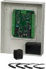
... can be distributed throughout the Reader Power or AUX Power in non-volatile FLASH memory. NetAXS Access Control Unit NX4S1 Installation Guide, Document 800-00008, Revision A 7 The NetAXS™ panel may be used as a fully monitored online access control device. NetAXS™...; NX4S1 Installation Panel Components and Descriptions Note: Maintain at least a .25-inch distance between the non-power limited wiring battery backup/charger wiring)...
... can be distributed throughout the Reader Power or AUX Power in non-volatile FLASH memory. NetAXS Access Control Unit NX4S1 Installation Guide, Document 800-00008, Revision A 7 The NetAXS™ panel may be used as a fully monitored online access control device. NetAXS™...; NX4S1 Installation Panel Components and Descriptions Note: Maintain at least a .25-inch distance between the non-power limited wiring battery backup/charger wiring)...
Installation Guide
Page 19
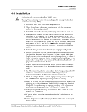
...; panel at power up properly (see "System Configuration" on page 26 and "Jumper Settings" on page 47). NetAXS Access Control Unit NX4S1 Installation Guide, Document 800-00008, Revision A 9 Review the panel layout, cable runs, and power needs. 2. The AC input must be sure ...up to a receptacle controlled by following UL-listed, 50 VA, Class 2 transformers: Basler Electric Model BE156250CAA0004, M&G Electronics Model MGT1650, or Honeywell Access Systems part number X-4. Check all I/O wires to the grounding stud. Run appropriate length of two-wire, 18 AWG shielded cable from ...
...; panel at power up properly (see "System Configuration" on page 26 and "Jumper Settings" on page 47). NetAXS Access Control Unit NX4S1 Installation Guide, Document 800-00008, Revision A 9 Review the panel layout, cable runs, and power needs. 2. The AC input must be sure ...up to a receptacle controlled by following UL-listed, 50 VA, Class 2 transformers: Basler Electric Model BE156250CAA0004, M&G Electronics Model MGT1650, or Honeywell Access Systems part number X-4. Check all I/O wires to the grounding stud. Run appropriate length of two-wire, 18 AWG shielded cable from ...

Installation Guide
Page 21
... Cabinet, Top View Back NetAXS™ NX4S1 Installation Installation 0 31/32" (25 mm) 13 9/32" (337.5 mm) 14 9/32" (362.5 mm) 0 3/4" (18.75 mm) 14/16" (21.875 mm) diameter knockout 1 1/4" (31.875 mm) diameter knockout 0 1 11/32" (34.375 mm) 4 7/32" (107.5 mm) Figure 4: NetAXS™ NX4S1 Panel Cabinet, Bottom View All knockouts... mm) diameter knockout 1 16/32" (38.275 mm) Back 14 9/32" (362.5 mm) 13 9/32" (337.5 mm) 31/32" (25 mm) 0 NetAXS Access Control Unit NX4S1 Installation Guide, Document 800-00008, Revision A 11
... Cabinet, Top View Back NetAXS™ NX4S1 Installation Installation 0 31/32" (25 mm) 13 9/32" (337.5 mm) 14 9/32" (362.5 mm) 0 3/4" (18.75 mm) 14/16" (21.875 mm) diameter knockout 1 1/4" (31.875 mm) diameter knockout 0 1 11/32" (34.375 mm) 4 7/32" (107.5 mm) Figure 4: NetAXS™ NX4S1 Panel Cabinet, Bottom View All knockouts... mm) diameter knockout 1 16/32" (38.275 mm) Back 14 9/32" (362.5 mm) 13 9/32" (337.5 mm) 31/32" (25 mm) 0 NetAXS Access Control Unit NX4S1 Installation Guide, Document 800-00008, Revision A 11
Installation Guide
Page 25
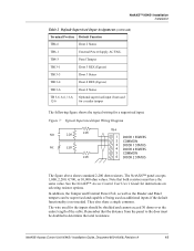
...door must have the same value. The wire used for the inputs should be supervised and capable of the cable. NetAXS Access Control Unit NX4S1 Installation Guide, Document 800-00008, Revision A 15 Figure 7: Typical Supervised Input Wiring Diagram NO 2.2K 2.2K NC 2.2K 2.2K TB 4 1...total resistance. See the NetAXS™ Access Control Unit User's Guide for a supervised input. The NetAXS™ panel accepts 1,000, 2,200, 4,700, or 10,000 ohm values. NetAXS™ NX4S1 Installation Installation Table 2 Default Supervised Input Assignments (continued) Terminal Position Default ...
...door must have the same value. The wire used for the inputs should be supervised and capable of the cable. NetAXS Access Control Unit NX4S1 Installation Guide, Document 800-00008, Revision A 15 Figure 7: Typical Supervised Input Wiring Diagram NO 2.2K 2.2K NC 2.2K 2.2K TB 4 1...total resistance. See the NetAXS™ Access Control Unit User's Guide for a supervised input. The NetAXS™ panel accepts 1,000, 2,200, 4,700, or 10,000 ohm values. NetAXS™ NX4S1 Installation Installation Table 2 Default Supervised Input Assignments (continued) Terminal Position Default ...
Installation Guide
Page 27
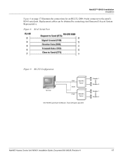
Two COM ports possible. Reader 1 Reader 4 Reader 1 Reader 4 NetAXS Access Control Unit NX4S1 Installation Guide, Document 800-00008, Revision A 17 Replacement cables can be obtained by contacting your Honeywell Access System Representative. NetAXS™ NX4S1 Installation Installation Figure 8 on page 17 illustrates the connections for an RS-232, DB9 (9 pin) connector to the panel's RJ-45 serial port. Figure 8: RJ-45 Serial Port Figure 9: RS-232 Configuration Terminal COM1 CBL50 NetAXS Panel COM2 NetAXS Panel One NetAXS panel per COM port.
Two COM ports possible. Reader 1 Reader 4 Reader 1 Reader 4 NetAXS Access Control Unit NX4S1 Installation Guide, Document 800-00008, Revision A 17 Replacement cables can be obtained by contacting your Honeywell Access System Representative. NetAXS™ NX4S1 Installation Installation Figure 8 on page 17 illustrates the connections for an RS-232, DB9 (9 pin) connector to the panel's RJ-45 serial port. Figure 8: RJ-45 Serial Port Figure 9: RS-232 Configuration Terminal COM1 CBL50 NetAXS Panel COM2 NetAXS Panel One NetAXS panel per COM port.
Installation Guide
Page 29
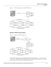
NetAXS Access Control Unit NX4S1 Installation Guide, Document 800-00008, Revision A 19 The Ethernet TCP/IP interface provides 10/100 Mbit Ethernet support for an Ethernet TCP/IP interface (see Figure 12, ... Card Inside PC Ethernet Up to 31 panels can be configured on each panel. Figure 11: RS-485 Configuration via NetAXS™ Gateway NetAXS™ NX4S1 Installation Installation COM1 Terminal RS-485 Multidrop Line NetAXS Gateway Reader 1 Reader 4 NetAXS Reader 1 NS2+ Reader 4 Reader 1 Reader 2 NetAXS A combination of NetAXS and NS2+ panels, supporting a total...
NetAXS Access Control Unit NX4S1 Installation Guide, Document 800-00008, Revision A 19 The Ethernet TCP/IP interface provides 10/100 Mbit Ethernet support for an Ethernet TCP/IP interface (see Figure 12, ... Card Inside PC Ethernet Up to 31 panels can be configured on each panel. Figure 11: RS-485 Configuration via NetAXS™ Gateway NetAXS™ NX4S1 Installation Installation COM1 Terminal RS-485 Multidrop Line NetAXS Gateway Reader 1 Reader 4 NetAXS Reader 1 NS2+ Reader 4 Reader 1 Reader 2 NetAXS A combination of NetAXS and NS2+ panels, supporting a total...
Installation Guide
Page 31
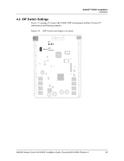
NetAXS™ NX4S1 Installation Installation 4.6 DIP Switch Settings Figure 14 on page 21 locates the NX4S1 DIP switch panel and the J36 and J37 (termination and biasing) jumpers. Figure 14: DIP Switch and Jumper Locations J37 J36 DIP Switches NetAXS Access Control Unit NX4S1 Installation Guide, Document 800-00008, Revision A 21
NetAXS™ NX4S1 Installation Installation 4.6 DIP Switch Settings Figure 14 on page 21 locates the NX4S1 DIP switch panel and the J36 and J37 (termination and biasing) jumpers. Figure 14: DIP Switch and Jumper Locations J37 J36 DIP Switches NetAXS Access Control Unit NX4S1 Installation Guide, Document 800-00008, Revision A 21
Installation Guide
Page 33
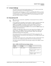
... rate (switches 7 and 8) - 7 = OFF, 8 = ON OP Mode (switches 9 and 10) - 9 = OFF, 10 = OFF NetAXS Access Control Unit NX4S1 Installation Guide, Document 800-00008, Revision A 23 The downstream I /O) bus. The downstream bus has a fixed baud rate and communicates to 1,000 ohms resistance. The MIRO-2/16 has... two supervised inputs and 16 SPDT relay outputs; NetAXS™ NX4S1 Installation Installation 4.7 Jumper Settings The NX4S1 panel control board includes jumpers 36 and 37, which set end-of-line termination and biasing for proper ...
... rate (switches 7 and 8) - 7 = OFF, 8 = ON OP Mode (switches 9 and 10) - 9 = OFF, 10 = OFF NetAXS Access Control Unit NX4S1 Installation Guide, Document 800-00008, Revision A 23 The downstream I /O) bus. The downstream bus has a fixed baud rate and communicates to 1,000 ohms resistance. The MIRO-2/16 has... two supervised inputs and 16 SPDT relay outputs; NetAXS™ NX4S1 Installation Installation 4.7 Jumper Settings The NX4S1 panel control board includes jumpers 36 and 37, which set end-of-line termination and biasing for proper ...
Installation Guide
Page 35
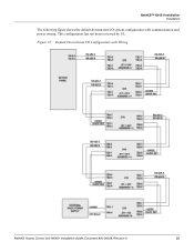
This configuration has not been reviewed by UL. Figure 15: Default Downstream I /O system configuration with Wiring NetAXS Access Control Unit NX4S1 Installation Guide, Document 800-00008, Revision A 25 NetAXS™ NX4S1 Installation Installation The following figure shows the default downstream I /O Configuration with communication and power wiring.
This configuration has not been reviewed by UL. Figure 15: Default Downstream I /O system configuration with Wiring NetAXS Access Control Unit NX4S1 Installation Guide, Document 800-00008, Revision A 25 NetAXS™ NX4S1 Installation Installation The following figure shows the default downstream I /O Configuration with communication and power wiring.

Installation Guide
Page 37
... See RS-485 Only Earth Ground (EG) one NetAXS™ Access Controller panels for each NetAXS enclosure individually NetAXS Access Control Unit NX4S1 Installation Guide, Document 800-00008, Revision A 27 It has been reviewed by UL. Figure 17: RS-485 Connection via NetAXS™ This ...connection supports thirty-one side of cable Cable Note EG EG It is recommended to illustrate the installation and programming of the NetAXS™ panel. NetAXS™ NX4S1 Installation System Configuration 5.2 RS-485 Connection via NetAXS™ Terminal COM Port RS-232 (50 Ft. Max.)...
... See RS-485 Only Earth Ground (EG) one NetAXS™ Access Controller panels for each NetAXS enclosure individually NetAXS Access Control Unit NX4S1 Installation Guide, Document 800-00008, Revision A 27 It has been reviewed by UL. Figure 17: RS-485 Connection via NetAXS™ This ...connection supports thirty-one side of cable Cable Note EG EG It is recommended to illustrate the installation and programming of the NetAXS™ panel. NetAXS™ NX4S1 Installation System Configuration 5.2 RS-485 Connection via NetAXS™ Terminal COM Port RS-232 (50 Ft. Max.)...
Installation Guide
Page 39
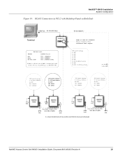
Max.) Terminal RS-485 (4,000 Ft.) 4 485 ote DIP Switch Settings S1-S5 Panel Address S6: OFF J36 OPEN J37 OPEN NetAXS Panel EG EG n y ar roun one side of cable EG EG one side of cable EG EG It is recommended to Earth Ground (EG) each NetAXS enclosure individually NetAXS Access Control Unit NX4S1 Installation Guide, Document 800-00008, Revision A 29 NetAXS™ NX4S1 Installation System Configuration Figure 19: RS-485 Connection via PCI-2 with Multidrop Panels at Both Ends COM Port RS-232 (50 Ft.
Max.) Terminal RS-485 (4,000 Ft.) 4 485 ote DIP Switch Settings S1-S5 Panel Address S6: OFF J36 OPEN J37 OPEN NetAXS Panel EG EG n y ar roun one side of cable EG EG one side of cable EG EG It is recommended to Earth Ground (EG) each NetAXS enclosure individually NetAXS Access Control Unit NX4S1 Installation Guide, Document 800-00008, Revision A 29 NetAXS™ NX4S1 Installation System Configuration Figure 19: RS-485 Connection via PCI-2 with Multidrop Panels at Both Ends COM Port RS-232 (50 Ft.
Installation Guide
Page 41
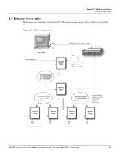
Figure 21: Ethernet Connection NIC Terminal RS-485 Multidrop 100BaseT (CAT 5) 328 Ft. Max. DIP Switch Settings S1-S5 Panel Address S6: OFF RS-485 Multidrop NetAXS Panel EG EG EG EG NetAXS Access Control Unit NX4S1 Installation Guide, Document 800-00008, Revision A 31 It has not been reviewed by UL. NetAXS™ NX4S1 Installation System Configuration 5.5 Ethernet Connection This connection supports a maximum of 255 IP connections per server.
Figure 21: Ethernet Connection NIC Terminal RS-485 Multidrop 100BaseT (CAT 5) 328 Ft. Max. DIP Switch Settings S1-S5 Panel Address S6: OFF RS-485 Multidrop NetAXS Panel EG EG EG EG NetAXS Access Control Unit NX4S1 Installation Guide, Document 800-00008, Revision A 31 It has not been reviewed by UL. NetAXS™ NX4S1 Installation System Configuration 5.5 Ethernet Connection This connection supports a maximum of 255 IP connections per server.
Installation Guide
Page 43
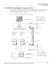
... MODEM PC (DB-9) DTE DCE (Straight) (Null) 2 TX 3 RX 5 Comm 2 (TX) 2 (RX) 3 (RX) or 3 (TX) 7 (GND) 7 (GND) NetAXS Access Control Unit NX4S1 Installation Guide, Document 800-00008, Revision A 33 NetAXS™ NX4S1 Installation System Configuration 5.7 RS-485 Short Haul Modem Connection via PCI-2 RS-232, 50 Ft. Note that PCI-2 units can also be wired...
... MODEM PC (DB-9) DTE DCE (Straight) (Null) 2 TX 3 RX 5 Comm 2 (TX) 2 (RX) 3 (RX) or 3 (TX) 7 (GND) 7 (GND) NetAXS Access Control Unit NX4S1 Installation Guide, Document 800-00008, Revision A 33 NetAXS™ NX4S1 Installation System Configuration 5.7 RS-485 Short Haul Modem Connection via PCI-2 RS-232, 50 Ft. Note that PCI-2 units can also be wired...


