Installation Guide
Page 3
... Optional AC Inlet 10 4.2 Tying the Field Wiring in the NX4L1 Cabinet 11 4.3 Cabinet Mounting ...12 4.4 Reader Wiring...16 4.5 Supervised Input Wiring 17 4.6 NX4L1 Control Output Wiring 18 4.7 Communications ...21 RS-232 Communications 21 RS-485 Communications 22 Ethernet TCP/IP Communications 24 NetAXS Access Control Unit NX4L1 Installation Guide, Document 7-901099, Revision A iii
... Optional AC Inlet 10 4.2 Tying the Field Wiring in the NX4L1 Cabinet 11 4.3 Cabinet Mounting ...12 4.4 Reader Wiring...16 4.5 Supervised Input Wiring 17 4.6 NX4L1 Control Output Wiring 18 4.7 Communications ...21 RS-232 Communications 21 RS-485 Communications 22 Ethernet TCP/IP Communications 24 NetAXS Access Control Unit NX4L1 Installation Guide, Document 7-901099, Revision A iii

Installation Guide
Page 4
...NetAXS™/NetAXS™ Access Controller Panel Connection Detail 46 6.0 NetAXS™ Startup ...47 6.1 LED Operation...47 7.0 Hardware Specifications ...49 7.1 Relay Contacts ...49 7.2 Reader Interface ...49 7.3 Maximum Output Loading 49 7.4 Common Connections...49 7.5 Mechanical...49 7.6 Environment...50 7.7 Communications and Wiring 50 7.8 Reader Wiring...51 7.9 NX4L1... Panel Wiring Diagram 52 8.0 Maintenance...53 9.0 Troubleshooting ...55 10.0 Technical Support...56 10.1 Normal Support Hours 56 10.2 Web ...56 iv www.honeywell.com
...NetAXS™/NetAXS™ Access Controller Panel Connection Detail 46 6.0 NetAXS™ Startup ...47 6.1 LED Operation...47 7.0 Hardware Specifications ...49 7.1 Relay Contacts ...49 7.2 Reader Interface ...49 7.3 Maximum Output Loading 49 7.4 Common Connections...49 7.5 Mechanical...49 7.6 Environment...50 7.7 Communications and Wiring 50 7.8 Reader Wiring...51 7.9 NX4L1... Panel Wiring Diagram 52 8.0 Maintenance...53 9.0 Troubleshooting ...55 10.0 Technical Support...56 10.1 Normal Support Hours 56 10.2 Web ...56 iv www.honeywell.com

Installation Guide
Page 5
... Card Read / Door Lock Operation 57 A.1.2 Door Egress / Door Lock / Door Status Operation 57 A.2 Standalone Settings...58 A.2.1 NetAXS™ Panel Hardware Settings 58 A.2.2 Communication Settings 58 A.2.3 Emulation Settings ...58 A.2.4 Verifying Communications 58 A.3 Standalone Commands...59 A.3.1... (Card Delete) Command 62 A.3.6 W (Input) Command ...63 A.3.7 P (Interlock) Command 63 A.3.8 Flow Control Disable/Enable Command 64 A.4 NetAXS™ Panel Defaults ...65 A.4.1 Reader Ports ...65 A.4.2 Reader LED Outputs 65 A.4.3 Reader Tamper Inputs 66 A.4.4 Door Egress Inputs...66 A.4.5 ...
... Card Read / Door Lock Operation 57 A.1.2 Door Egress / Door Lock / Door Status Operation 57 A.2 Standalone Settings...58 A.2.1 NetAXS™ Panel Hardware Settings 58 A.2.2 Communication Settings 58 A.2.3 Emulation Settings ...58 A.2.4 Verifying Communications 58 A.3 Standalone Commands...59 A.3.1... (Card Delete) Command 62 A.3.6 W (Input) Command ...63 A.3.7 P (Interlock) Command 63 A.3.8 Flow Control Disable/Enable Command 64 A.4 NetAXS™ Panel Defaults ...65 A.4.1 Reader Ports ...65 A.4.2 Reader LED Outputs 65 A.4.3 Reader Tamper Inputs 66 A.4.4 Door Egress Inputs...66 A.4.5 ...

Installation Guide
Page 7
... Figure 2: Tying the Field Wiring in the NX4L1 Cabinet 11 Figure 3: NetAXS™ Panel Cabinet, Back View 12 Figure 4: NetAXS™ Panel Cabinet, Top View 13 Figure 5: NetAXS™ Panel Cabinet, Bottom View 13 Figure 6: NetAXS™ Panel Cabinet, Left View 14 Figure 7: NetAXS™ Panel Cabinet, Right View 15 Figure ...: RS-232 Configuration 22 Figure 12: RS-485 Configuration via N-485-PCI-2 or PCI-3 23 Figure 13: RS-485 Configuration via NetAXS™ Gateway 23 Figure 14: Ethernet TCP/IP Configuration 24 Figure 15: Ethernet MAC Address Location 25 Figure 16: DIP Switch and ...
... Figure 2: Tying the Field Wiring in the NX4L1 Cabinet 11 Figure 3: NetAXS™ Panel Cabinet, Back View 12 Figure 4: NetAXS™ Panel Cabinet, Top View 13 Figure 5: NetAXS™ Panel Cabinet, Bottom View 13 Figure 6: NetAXS™ Panel Cabinet, Left View 14 Figure 7: NetAXS™ Panel Cabinet, Right View 15 Figure ...: RS-232 Configuration 22 Figure 12: RS-485 Configuration via N-485-PCI-2 or PCI-3 23 Figure 13: RS-485 Configuration via NetAXS™ Gateway 23 Figure 14: Ethernet TCP/IP Configuration 24 Figure 15: Ethernet MAC Address Location 25 Figure 16: DIP Switch and ...

Installation Guide
Page 9
LIST OF TABLES Table 1 Cabinet Electrical Entries 16 Table 2 Reader Wiring ...16 Table 3 Default Supervised Input Assignments 17 Table 5 DIP Switch Settings ...27 Table 6 MIRO 32/0 DIP Switch and Jumper Settings 28 Table 7 LED Status ...48 Table 8 Communications and Wiring 50 Table 9 Reader Wiring ...51 Table 10 Troubleshooting Problems and Solutions 55 NetAXS Access Control Unit NX4L1 Installation Guide, Document 7-901099, Revision A ix
LIST OF TABLES Table 1 Cabinet Electrical Entries 16 Table 2 Reader Wiring ...16 Table 3 Default Supervised Input Assignments 17 Table 5 DIP Switch Settings ...27 Table 6 MIRO 32/0 DIP Switch and Jumper Settings 28 Table 7 LED Status ...48 Table 8 Communications and Wiring 50 Table 9 Reader Wiring ...51 Table 10 Troubleshooting Problems and Solutions 55 NetAXS Access Control Unit NX4L1 Installation Guide, Document 7-901099, Revision A ix

Installation Guide
Page 11
... should always meet local fire and safety code requirements. Honeywell Access Systems (HAS) recommends only DC locks. Warning: Earth ground all door locks. To prevent damage always follow these procedures: NetAXS Access Control Unit NX4L1 Installation Guide, Document 7-901099, Revision A 1 Use ...of the power supply. • Do not apply power to do is a life safety requirement. Warning: Honeywell never recommends using an electronic product to ...
... should always meet local fire and safety code requirements. Honeywell Access Systems (HAS) recommends only DC locks. Warning: Earth ground all door locks. To prevent damage always follow these procedures: NetAXS Access Control Unit NX4L1 Installation Guide, Document 7-901099, Revision A 1 Use ...of the power supply. • Do not apply power to do is a life safety requirement. Warning: Honeywell never recommends using an electronic product to ...

Installation Guide
Page 12
... Communications Products and Upgrade kits is determined to be defective as a result of the defective Product or the negligence of Honeywell, its agents or its Products shall be free from defects in materials and workmanship for a period of one year from ... are available from various vendors. 1.2 Product Liability, Mutual Indemnification In the event that a Customer receives a claim that its employees. NetAXS™ NX4L1 Installation Notices • Use static shield packaging and containers to transport all electronic components, including completed reader assemblies. • Handle all...
... Communications Products and Upgrade kits is determined to be defective as a result of the defective Product or the negligence of Honeywell, its agents or its Products shall be free from defects in materials and workmanship for a period of one year from ... are available from various vendors. 1.2 Product Liability, Mutual Indemnification In the event that a Customer receives a claim that its employees. NetAXS™ NX4L1 Installation Notices • Use static shield packaging and containers to transport all electronic components, including completed reader assemblies. • Handle all...

Installation Guide
Page 13
..., LOSS OF PROFITS, LOSS OF USE, INCIDENTAL, CONSEQUENTIAL OR SPECIAL DAMAGES TO ANY PERSON RESULTING FROM THE USE OF HONEYWELL PRODUCTS. 1.4 Federal Communications Commission This equipment has been tested and found to comply with the instructions, may cause harmful ... encouraged to try to correct the interference by the Installation Instructions or User's Manual. NetAXS™ NX4L1 Installation Notices THERE ARE NO WARRANTIES THAT EXTEND BEYOND THIS PROVISION. NetAXS Access Control Unit NX4L1 Installation Guide, Document 7-901099, Revision A 3 For panels using the Ethernet connection, ...
..., LOSS OF PROFITS, LOSS OF USE, INCIDENTAL, CONSEQUENTIAL OR SPECIAL DAMAGES TO ANY PERSON RESULTING FROM THE USE OF HONEYWELL PRODUCTS. 1.4 Federal Communications Commission This equipment has been tested and found to comply with the instructions, may cause harmful ... encouraged to try to correct the interference by the Installation Instructions or User's Manual. NetAXS™ NX4L1 Installation Notices THERE ARE NO WARRANTIES THAT EXTEND BEYOND THIS PROVISION. NetAXS Access Control Unit NX4L1 Installation Guide, Document 7-901099, Revision A 3 For panels using the Ethernet connection, ...
Installation Guide
Page 14
... page 35 of downstream I/O devices (see Section 4.10, "Downstream I/O" on page 28) with the NetAXS panel. 4 www.honeywell.com Category APOU, UL1076 standard. NetAXS™ NX4L1 Installation Notices 1.6 Underwriters Laboratories Incorporated The NetAXS™ panel was reviewed using the following Honeywell readers: OmniAssure (TM) OT30, OmniClass (TM) OM40 and OM55, and OmniProx (TM) OP30 and OP40...
... page 35 of downstream I/O devices (see Section 4.10, "Downstream I/O" on page 28) with the NetAXS panel. 4 www.honeywell.com Category APOU, UL1076 standard. NetAXS™ NX4L1 Installation Notices 1.6 Underwriters Laboratories Incorporated The NetAXS™ panel was reviewed using the following Honeywell readers: OmniAssure (TM) OT30, OmniClass (TM) OM40 and OM55, and OmniProx (TM) OP30 and OP40...

Installation Guide
Page 15
... creation and modification of hardware and software, usually configured in a network environment over the RS-232 and RS-485 network protocols. NetAXS Access Control Unit NX4L1 Installation Guide, Document 7-901099, Revision A 5 Access control units, readers, door strikes, and video and other and with each ...and monitor the access to specific areas and resources. See "System Configuration" on page 31 to install and configure the NX4L1 access control unit. A NetAXS™ access control system is verified, the system then either the host system or a web server using RS-232,...
... creation and modification of hardware and software, usually configured in a network environment over the RS-232 and RS-485 network protocols. NetAXS Access Control Unit NX4L1 Installation Guide, Document 7-901099, Revision A 5 Access control units, readers, door strikes, and video and other and with each ...and monitor the access to specific areas and resources. See "System Configuration" on page 31 to install and configure the NX4L1 access control unit. A NetAXS™ access control system is verified, the system then either the host system or a web server using RS-232,...
Installation Guide
Page 16
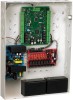
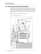
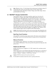
...are enclosed in cases of a NetAXS panel control board, a power distribution module, a power supply, and batteries. The following figure shows the NX4L1 panel components. The control board... is a four-reader panel providing access control for up to four doors. Figure 1: NX4L1 Panel Components Enclosure Tamper Switch ...24VDC Power Supply (cover not shown) Mounting Screw 3.5A 250V Fuse Cables with heat shrink barriers NetAXS Access Control Panel...
...are enclosed in cases of a NetAXS panel control board, a power distribution module, a power supply, and batteries. The following figure shows the NX4L1 panel components. The control board... is a four-reader panel providing access control for up to four doors. Figure 1: NX4L1 Panel Components Enclosure Tamper Switch ...24VDC Power Supply (cover not shown) Mounting Screw 3.5A 250V Fuse Cables with heat shrink barriers NetAXS Access Control Panel...
Installation Guide
Page 17
... a fully monitored online access control device. Only through the relay board can the common power supply be used to power locks. NetAXS Access Control Unit NX4L1 Installation Guide, Document 7-901099, Revision A 7 NetAXS™ NX4L1 Installation Panel Components and Descriptions Note: Maintain at least a .25-inch distance between the non-power limited wiring (115 VAC...
... a fully monitored online access control device. Only through the relay board can the common power supply be used to power locks. NetAXS Access Control Unit NX4L1 Installation Guide, Document 7-901099, Revision A 7 NetAXS™ NX4L1 Installation Panel Components and Descriptions Note: Maintain at least a .25-inch distance between the non-power limited wiring (115 VAC...
Installation Guide
Page 18
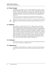
... often if the system has a high rate of 3.5A, 250V. 3.3 Batteries For the NX4L1, two CASIL CA1270, 12 VDC, 7 AHr sealed lead-acud batteries (Honeywell order number 3-000066) wired in the NetAXS™ enclosure. Replace the batteries every 2 to operate the system. Wire the unswitched electrical power... Amps for continuous 24 VDC power. The supply also charges and monitors the condition of the batteries. NetAXS™ NX4L1 Installation Panel Components and Descriptions 3.2 Power Supply The NX4L1 uses an internal 115 VAC to the panel if it is present. The power supply has deep discharge...
... often if the system has a high rate of 3.5A, 250V. 3.3 Batteries For the NX4L1, two CASIL CA1270, 12 VDC, 7 AHr sealed lead-acud batteries (Honeywell order number 3-000066) wired in the NetAXS™ enclosure. Replace the batteries every 2 to operate the system. Wire the unswitched electrical power... Amps for continuous 24 VDC power. The supply also charges and monitors the condition of the batteries. NetAXS™ NX4L1 Installation Panel Components and Descriptions 3.2 Power Supply The NX4L1 uses an internal 115 VAC to the panel if it is present. The power supply has deep discharge...

Installation Guide
Page 19
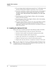
... (115 VAC/60 Hz input wiring, power line filter wiring, 24 VDC wiring, battery backup/charger wiring, and battery-to 12 AWG. NetAXS Access Control Unit NX4L1 Installation Guide, Document 7-901099, Revision A 9 Run all wiring at this time. Note that the ground wire is power-limited Class 2 ...wires to the appropriate terminal on page 47). 10.Configure the panel by following steps to install the NX4L1 panel: Warning: Use a static strap whenever touching the panel to the NetAXS™ at this time. 6. The power inlet terminal block can cause damage to ensure protection from ...
... (115 VAC/60 Hz input wiring, power line filter wiring, 24 VDC wiring, battery backup/charger wiring, and battery-to 12 AWG. NetAXS Access Control Unit NX4L1 Installation Guide, Document 7-901099, Revision A 9 Run all wiring at this time. Note that the ground wire is power-limited Class 2 ...wires to the appropriate terminal on page 47). 10.Configure the panel by following steps to install the NX4L1 panel: Warning: Use a static strap whenever touching the panel to the NetAXS™ at this time. 6. The power inlet terminal block can cause damage to ensure protection from ...
Installation Guide
Page 20
...backup function, place the two 7 A-Hr batteries in , until it snaps into place. 4. Feed the AC inlet assembly wires through the opening from Honeywell. 10 www.honeywell.com Plug the other end of this power cord from the outside. 3. UL has evaluated the use of the cable into the three-prong...straight in the enclosure with the optional AC inlet for the panel to install the optional AC inlet (HAS part number 100-00049): 1. NetAXS™ NX4L1 Installation Installation 11.If you are using the Ethernet connection, the cable clamp (HAS part number 3-000342) must be used for the...
...backup function, place the two 7 A-Hr batteries in , until it snaps into place. 4. Feed the AC inlet assembly wires through the opening from Honeywell. 10 www.honeywell.com Plug the other end of this power cord from the outside. 3. UL has evaluated the use of the cable into the three-prong...straight in the enclosure with the optional AC inlet for the panel to install the optional AC inlet (HAS part number 100-00049): 1. NetAXS™ NX4L1 Installation Installation 11.If you are using the Ethernet connection, the cable clamp (HAS part number 3-000342) must be used for the...
Installation Guide
Page 21
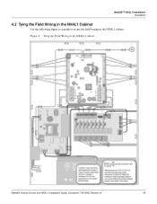
... Guide, Document 7-901099, Revision A 11 NetAXS™ NX4L1 Installation Installation 4.2 Tying the Field Wiring in the NX4L1 cabinet. Figure 2: Tying the Field Wiring in the NX4L1 Cabinet Location of wire tie points Pb Pb and suggested routing of 0.25 inch spacing from non-power- limited wiring.... Wiring shown as a guide to maintain a minimum of Class 2 power-limited field wiring to secure the field wiring in the NX4L1 Cabinet Use the following figure as represent shrink wrap barrier protection (0.028 inch thickness minimum) where spacing between non-power-limited and power-...
... Guide, Document 7-901099, Revision A 11 NetAXS™ NX4L1 Installation Installation 4.2 Tying the Field Wiring in the NX4L1 cabinet. Figure 2: Tying the Field Wiring in the NX4L1 Cabinet Location of wire tie points Pb Pb and suggested routing of 0.25 inch spacing from non-power- limited wiring.... Wiring shown as a guide to maintain a minimum of Class 2 power-limited field wiring to secure the field wiring in the NX4L1 Cabinet Use the following figure as represent shrink wrap barrier protection (0.028 inch thickness minimum) where spacing between non-power-limited and power-...

Installation Guide
Page 22
NetAXS™ NX4L1 Installation Installation 4.3 Cabinet Mounting The following five figures show the back, top, bottom, right, and left views of the conduit entries into the cabinet.NetAXS™ Panel Cabinet, Back View Figure 3: NetAXS™ Panel Cabinet, Back View 0 27/32" (21.8 mm) 2 9/16" (65 mm) 8 27/32" (225 mm) 15 5/32" (385 mm....51 mm) 15/32" (11.51 mm) 15/32" (11.51 mm) 9 3/8" (238.50 mm) 23 1/8" (587 mm) 23 29/32" (607 mm) 12 www.honeywell.com 27/32" (21.8 mm) 16 5/32" (410 mm) 16 17/32" (420 mm) 16 27/32" (428.2 mm) 22 29/32" (581.6 mm) Each...
NetAXS™ NX4L1 Installation Installation 4.3 Cabinet Mounting The following five figures show the back, top, bottom, right, and left views of the conduit entries into the cabinet.NetAXS™ Panel Cabinet, Back View Figure 3: NetAXS™ Panel Cabinet, Back View 0 27/32" (21.8 mm) 2 9/16" (65 mm) 8 27/32" (225 mm) 15 5/32" (385 mm....51 mm) 15/32" (11.51 mm) 15/32" (11.51 mm) 9 3/8" (238.50 mm) 23 1/8" (587 mm) 23 29/32" (607 mm) 12 www.honeywell.com 27/32" (21.8 mm) 16 5/32" (410 mm) 16 17/32" (420 mm) 16 27/32" (428.2 mm) 22 29/32" (581.6 mm) Each...
Installation Guide
Page 26
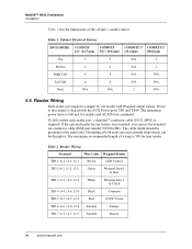
... TB5-4, 6-4, 11-4, 12-4 Black Common TB5-5, 6-5, 11-5, 12-5 Red 12VDC Power TB5-6, 6-6, 11-6, 12-6 Variable Tamper TB5-7, 6-7, 11-7, 12-7 Variable Buzzer 16 www.honeywell.com To fully utilize each reader port, a shielded 7-conductor cable (18-22 AWG) is 600 mA for readers and AUX Power combined. If the optional...six-conductor cable (HAS part number NC1861-BL). The maximum recommended length of the cabinet's conduit entries. The cable shield should be disruptive. NetAXS™ NX4L1 Installation Installation Table 1 lists the dimensions of wiring is 500 feet per reader.
... TB5-4, 6-4, 11-4, 12-4 Black Common TB5-5, 6-5, 11-5, 12-5 Red 12VDC Power TB5-6, 6-6, 11-6, 12-6 Variable Tamper TB5-7, 6-7, 11-7, 12-7 Variable Buzzer 16 www.honeywell.com To fully utilize each reader port, a shielded 7-conductor cable (18-22 AWG) is 600 mA for readers and AUX Power combined. If the optional...six-conductor cable (HAS part number NC1861-BL). The maximum recommended length of the cabinet's conduit entries. The cable shield should be disruptive. NetAXS™ NX4L1 Installation Installation Table 1 lists the dimensions of wiring is 500 feet per reader.
Installation Guide
Page 27
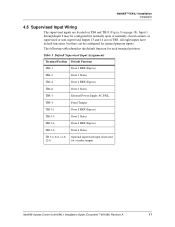
... and 14 are located on TB4 and TB13 (Figure 8 on TB8. All eight inputs have default functions, but they can be configured for a reader tamper NetAXS Access Control Unit NX4L1 Installation Guide, Document 7-901099, Revision A 17 NetAXS™ NX4L1 Installation Installation 4.5 Supervised Input Wiring The supervised inputs are on page 18).
... and 14 are located on TB4 and TB13 (Figure 8 on TB8. All eight inputs have default functions, but they can be configured for a reader tamper NetAXS Access Control Unit NX4L1 Installation Guide, Document 7-901099, Revision A 17 NetAXS™ NX4L1 Installation Installation 4.5 Supervised Input Wiring The supervised inputs are on page 18).

Installation Guide
Page 28
...5-8 are used for instructions on selecting resistor options. Refer to the NetAXS Access Control Unit User's Guide for compliance with UL1076 Burglar Alarm units and systems. 4.6 NX4L1 Control Output Wiring The NX4L1 provides a Power Distribution Output circuit board that is not needed. Figure...the entire length of the Door 4 lock. The NX4L1 is defaulted for details. 18 www.honeywell.com Caution: The cable shield should be used as auxiliary relays. They also share a single common. NetAXS™ NX4L1 Installation Installation The following figure shows the typical wiring...
...5-8 are used for instructions on selecting resistor options. Refer to the NetAXS Access Control Unit User's Guide for compliance with UL1076 Burglar Alarm units and systems. 4.6 NX4L1 Control Output Wiring The NX4L1 provides a Power Distribution Output circuit board that is not needed. Figure...the entire length of the Door 4 lock. The NX4L1 is defaulted for details. 18 www.honeywell.com Caution: The cable shield should be used as auxiliary relays. They also share a single common. NetAXS™ NX4L1 Installation Installation The following figure shows the typical wiring...
