User Manual
Page 1
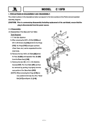
... the main body. Machine Screws [127]. C. Remove the four M10 x 40 Bolts [66] which fix the Hinge [119], the Hinge [119] and upper portions (Gear Case, etc.) can then be very careful not to commencing disassembly (including replacement of the saw blade), ensure that the plug is disconnected from the rear portion of the Base and Turn Table: Tools Required: • 17...
... the main body. Machine Screws [127]. C. Remove the four M10 x 40 Bolts [66] which fix the Hinge [119], the Hinge [119] and upper portions (Gear Case, etc.) can then be very careful not to commencing disassembly (including replacement of the saw blade), ensure that the plug is disconnected from the rear portion of the Base and Turn Table: Tools Required: • 17...
User Manual
Page 2
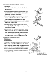
... Mark on the Saw Cover which indicates the rotational direction of the saw blade. Push the Gear Case [53] forward and down to its lowered position, and lock it is necessary to remove two of disassembly is necessary after releasing the fixing device (paragraph D.). D. Loosen the two M6 x 10 Hexagon Socket Hd. Tapping Screws [13] it in the Set Pin [97] to engage...
... Mark on the Saw Cover which indicates the rotational direction of the saw blade. Push the Gear Case [53] forward and down to its lowered position, and lock it is necessary to remove two of disassembly is necessary after releasing the fixing device (paragraph D.). D. Loosen the two M6 x 10 Hexagon Socket Hd. Tapping Screws [13] it in the Set Pin [97] to engage...
User Manual
Page 3
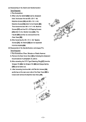
... from the Handle [20]. (5) Disassembly of the Spindle Section and stopper Pin: Tools Required: • Plus Screwdriver, Pliers, Wooden or Plastic Hammer A. Remove the Saw Cover Ass'y [3] by following the disassembly procedures in paragraph (3), above. Then loosen the two M5 x 12 -Hd. Tapping Screws [21], the Switch [22] can then be removed from the Stopper Pin [52], the Stopper Pin [52] and Gauge Spring [38...
... from the Handle [20]. (5) Disassembly of the Spindle Section and stopper Pin: Tools Required: • Plus Screwdriver, Pliers, Wooden or Plastic Hammer A. Remove the Saw Cover Ass'y [3] by following the disassembly procedures in paragraph (3), above. Then loosen the two M5 x 12 -Hd. Tapping Screws [21], the Switch [22] can then be removed from the Stopper Pin [52], the Stopper Pin [52] and Gauge Spring [38...
User Manual
Page 4
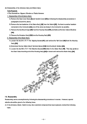
...24], cut off the wires as closely to loosen and remove the Stator Ass'y [46]. 1-2. Machine Screws [48] which fix the Stator Ass'y [46]. Remove the two Brush Caps [55] from the Brush Holders [56]. Loosen the two D4 x 10 -Hd. Then tap gently on the Gear Case mounting end ... Carbon Brushes [40]. Disassembly of the Housing Ass'y [84] to the Connector as possible. Disassembly of the Armature Ass'y and Stator Ass'y: Tools Required: • Plus Screwdriver, Nippers, Wooden or Plastic Hammer 1. Tapping Screws [41], and remove the Tail Cover [42] from the Switch [22]. C. Remove ...
...24], cut off the wires as closely to loosen and remove the Stator Ass'y [46]. 1-2. Machine Screws [48] which fix the Stator Ass'y [46]. Remove the two Brush Caps [55] from the Brush Holders [56]. Loosen the two D4 x 10 -Hd. Then tap gently on the Gear Case mounting end ... Carbon Brushes [40]. Disassembly of the Housing Ass'y [84] to the Connector as possible. Disassembly of the Armature Ass'y and Stator Ass'y: Tools Required: • Plus Screwdriver, Nippers, Wooden or Plastic Hammer 1. Tapping Screws [41], and remove the Tail Cover [42] from the Switch [22]. C. Remove ...
User Manual
Page 5
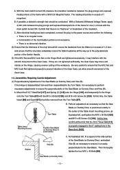
... Nut and M12 Lock Nut tightened properly to prevent vibration of the Gear Case, yet allow smooth movement of the Table Insert mounting groove, as necessary to ensure it is in the center of the Gear Case. 1-3. Mount the D12.7 Steel Ball [117] and Spring (C) [118] onto the Hinge [119], and temporarily fix the Hinge onto the Turn Table [87] with the smooth movement of the Saw Blade...
... Nut and M12 Lock Nut tightened properly to prevent vibration of the Gear Case, yet allow smooth movement of the Table Insert mounting groove, as necessary to ensure it is in the center of the Gear Case. 1-3. Mount the D12.7 Steel Ball [117] and Spring (C) [118] onto the Hinge [119], and temporarily fix the Hinge onto the Turn Table [87] with the smooth movement of the Saw Blade...
User Manual
Page 6
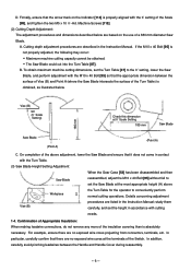
...; Scale Setting 185 mm Saw Blade 185 mm Saw Blade (Point A) (Point A) C. For example, ensure there are listed in the Instruction Manual. D. Finnally, ensure that it does not come in accordance with the 0˚ setting of the Switch. Cutting depth adjustment procedures are no exposed wire cores projecting from connectors, terminals, etc. On completion of the above Workpiece H the Turn Table for the operator to set the height...
...; Scale Setting 185 mm Saw Blade 185 mm Saw Blade (Point A) (Point A) C. For example, ensure there are listed in the Instruction Manual. D. Finnally, ensure that it does not come in accordance with the 0˚ setting of the Switch. Cutting depth adjustment procedures are no exposed wire cores projecting from connectors, terminals, etc. On completion of the above Workpiece H the Turn Table for the operator to set the height...
User Manual
Page 7
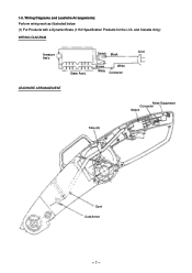
1-5. and Canada Only): WIRING DIAGRAM Armature Ass'y Stator Ass'y Switch Black Brown White White Connector Cord LEADWIRE ARRANGEMENT Noise Suppressor Connector Switch Tube (A) Cord Cord Armor --- 7 --- Wiring Diagrams and Leadwire Arrangements: Perform wiring work as illustrated below. (1) For Products with a Dynamic Brake (115V Specification Products for the U.S.
1-5. and Canada Only): WIRING DIAGRAM Armature Ass'y Stator Ass'y Switch Black Brown White White Connector Cord LEADWIRE ARRANGEMENT Noise Suppressor Connector Switch Tube (A) Cord Cord Armor --- 7 --- Wiring Diagrams and Leadwire Arrangements: Perform wiring work as illustrated below. (1) For Products with a Dynamic Brake (115V Specification Products for the U.S.
User Manual
Page 8
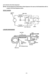
WIRING DIAGRAM Armature Ass'y Stator Ass'y LEADWIRE ARRANGEMENT Noise Suppressor Switch Vinyl Tube Black Red Black Red Green Terminal (w/o insulation tube) M5 x 75 Machine Screw Stator Core Noise Suppressor Yellow/Green Connector --- 8 --- (2) For Products with a Noise Suppressor: [NOTE] The wiring diagram for products without a Noise Suppressor is the same as that illustrated below with the exception of the Noise Suppressor section.
WIRING DIAGRAM Armature Ass'y Stator Ass'y LEADWIRE ARRANGEMENT Noise Suppressor Switch Vinyl Tube Black Red Black Red Green Terminal (w/o insulation tube) M5 x 75 Machine Screw Stator Core Noise Suppressor Yellow/Green Connector --- 8 --- (2) For Products with a Noise Suppressor: [NOTE] The wiring diagram for products without a Noise Suppressor is the same as that illustrated below with the exception of the Noise Suppressor section.
User Manual
Page 9
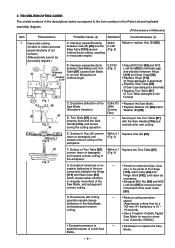
...) • Replace Gear Case [53]. (If Gear Case damaged or deformed) • Replace Turn Table [87]. (If Turn Table damaged or de- Fig. 2 D. Within 0.1 Replace Vise (B) [82]. (Fig. 3) Fig. 4 F. num (Code No. 959024). accurately aligned.) Perpendicularity Standard: 0.2/90 B. Excessive deflection of cut into Workpiece at inclined angle. 0.2/190 (Fig. 1) • Adjust M12 Nut [93] and M12 Lock Nut [92] to the item numbers in the Parts List and exploded assembly diagram. (All Dimensions in...
...) • Replace Gear Case [53]. (If Gear Case damaged or deformed) • Replace Turn Table [87]. (If Turn Table damaged or de- Fig. 2 D. Within 0.1 Replace Vise (B) [82]. (Fig. 3) Fig. 4 F. num (Code No. 959024). accurately aligned.) Perpendicularity Standard: 0.2/90 B. Excessive deflection of cut into Workpiece at inclined angle. 0.2/190 (Fig. 1) • Adjust M12 Nut [93] and M12 Lock Nut [92] to the item numbers in the Parts List and exploded assembly diagram. (All Dimensions in...
User Manual
Page 10
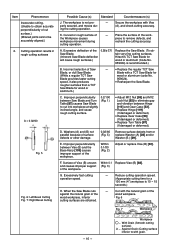
.... Improper perpendicularity between Saw Blade and Turn Table [87] causes Saw Blade to cut surface.) (Mitered joints cannot be accurately aligned.) 2. E. Within 0.1/80 (Fig. 2) Adjust or replace Vise (B) [82]. F. Excessively fast cutting operation speed. ---- Cut with grain. wood workpiece, inferior Fig. 6 cutting surfaces are obtained. Against Grain (Cutting surface inferior to eliminate gap and vibration between Vise (B) and the Base Ass'y [103] causes improper support of the wood...
.... Improper perpendicularity between Saw Blade and Turn Table [87] causes Saw Blade to cut surface.) (Mitered joints cannot be accurately aligned.) 2. E. Within 0.1/80 (Fig. 2) Adjust or replace Vise (B) [82]. F. Excessively fast cutting operation speed. ---- Cut with grain. wood workpiece, inferior Fig. 6 cutting surfaces are obtained. Against Grain (Cutting surface inferior to eliminate gap and vibration between Vise (B) and the Base Ass'y [103] causes improper support of the wood...
User Manual
Page 11
... workpiece to securely fix the Turn Table.) K. J. When performing cutting opera- Repair or adjust affected parts as described in position. L. Plane the surface of the workpiece causes workpiece movement during cutting operation. ---- Excessive vibration during cutting operation. ---- Excessive looseness or excessive tightening of Possible Causes A, B, D, J and K, above . M. Handle [116] without fail to fix the Turn Table in position. (The Ball Index Settings at 0˚, 15˚, 22.5˚...
... workpiece to securely fix the Turn Table.) K. J. When performing cutting opera- Repair or adjust affected parts as described in position. L. Plane the surface of the workpiece causes workpiece movement during cutting operation. ---- Excessive vibration during cutting operation. ---- Excessive looseness or excessive tightening of Possible Causes A, B, D, J and K, above . M. Handle [116] without fail to fix the Turn Table in position. (The Ball Index Settings at 0˚, 15˚, 22.5˚...


