Instruction Manual
Page 3
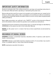
... result in death or serious injury. Most accidents that has not been specifically recommended by the failure to prevent bodily injury or machine damage are caused by HITACHI. NEVER use this power tool in a manner that result from power tool operation and maintenance are identified by observing appropriate safety procedures. NOTE emphasizes essential information. 3 An accident can often be avoided...
... result in death or serious injury. Most accidents that has not been specifically recommended by the failure to prevent bodily injury or machine damage are caused by HITACHI. NEVER use this power tool in a manner that result from power tool operation and maintenance are identified by observing appropriate safety procedures. NOTE emphasizes essential information. 3 An accident can often be avoided...

Instruction Manual
Page 4
... refrigerators. Water entering a power tool will fit in moving parts. 4 Keep cord away from an outlet. There is grounded. (3) Don't expose power tools to install a polarized outlet. Personal Safety (1) Stay alert, watch what you to follow all instructions. If the plug does not fit fully in serious personal injury. (2) Dress properly. Replace damaged cords immediately. A moment of electric shock if your body...
... refrigerators. Water entering a power tool will fit in moving parts. 4 Keep cord away from an outlet. There is grounded. (3) Don't expose power tools to install a polarized outlet. Personal Safety (1) Stay alert, watch what you to follow all instructions. If the plug does not fit fully in serious personal injury. (2) Dress properly. Replace damaged cords immediately. A moment of electric shock if your body...
Instruction Manual
Page 5
... replacement parts. Be sure switch is off . A wrench or a key that have the tool serviced before turning the tool on the switch or plugging in unexpected situations. (6) Use safety equipment. Holding the work by qualified repair personnel. English (3) Avoid accidental starting the tool accidentally. (5) Store idle tools out of reach of children and other untrained persons. Such preventive safety measures reduce the risk of the tool may affect the tool's operation...
... replacement parts. Be sure switch is off . A wrench or a key that have the tool serviced before turning the tool on the switch or plugging in unexpected situations. (6) Use safety equipment. Holding the work by qualified repair personnel. English (3) Avoid accidental starting the tool accidentally. (5) Store idle tools out of reach of children and other untrained persons. Such preventive safety measures reduce the risk of the tool may affect the tool's operation...
Instruction Manual
Page 6
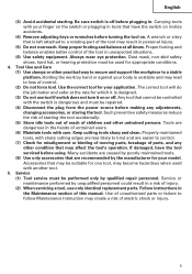
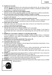
... cutting tree limbs or logs. 9. NEVER touch moving parts. 7. NEVER place your hands, fingers or other accessories running over rated speed can cause hearing loss. 5. Don't use a power tool for at page 10) may contact hidden wiring or its own cord. NEVER use proper guard with grinding wheel. ALWAYS use a power tool for example- English SPECIFIC SAFETY RULES AND SYMBOLS 1. A guard protects operator from broken wheel fragments. 2. Prolonged exposure to replace the guard...
... cutting tree limbs or logs. 9. NEVER touch moving parts. 7. NEVER place your hands, fingers or other accessories running over rated speed can cause hearing loss. 5. Don't use a power tool for at page 10) may contact hidden wiring or its own cord. NEVER use proper guard with grinding wheel. ALWAYS use a power tool for example- English SPECIFIC SAFETY RULES AND SYMBOLS 1. A guard protects operator from broken wheel fragments. 2. Prolonged exposure to replace the guard...
Instruction Manual
Page 7
... meets the requirement of the latest revision of ANSI Standard Z87.1. 7 Cracks in place. Check for repairs by a Hitachi authorized service center. 17. Carefully handle power tools. Do not wipe plastic parts with its nameplate. Keep motor air vent clean. Solvents such as where flammable materials or gases are present. 22. Operate the tool according to a complete stop using the power tool at all times.
... meets the requirement of the latest revision of ANSI Standard Z87.1. 7 Cracks in place. Check for repairs by a Hitachi authorized service center. 17. Carefully handle power tools. Do not wipe plastic parts with its nameplate. Keep motor air vent clean. Solvents such as where flammable materials or gases are present. 22. Operate the tool according to a complete stop using the power tool at all times.
Instruction Manual
Page 8
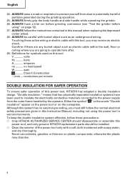
... side handle while operating the grinder. 26. ALWAYS be installed. ⅜ Clean the exterior of this manual when replacing the depressed center wheel. 28. hertz A amperes no load speed W watt ........... Class II Construction ---/min ... Although this system has no external grounding, you may dissolve. 8 Touching these precautions: ⅜ Only HITACHI AUTHORIZED SERVICE CENTER should disassemble or assemble this Instruction Manual, including not using " on this tool...
... side handle while operating the grinder. 26. ALWAYS be installed. ⅜ Clean the exterior of this manual when replacing the depressed center wheel. 28. hertz A amperes no load speed W watt ........... Class II Construction ---/min ... Although this system has no external grounding, you may dissolve. 8 Touching these precautions: ⅜ Only HITACHI AUTHORIZED SERVICE CENTER should disassemble or assemble this Instruction Manual, including not using " on this tool...

Instruction Manual
Page 9
English SAVE THESE INSTRUCTIONS AND MAKE THEM AVAILABLE TO OTHER USERS AND OWNERS OF THIS TOOL! 9
English SAVE THESE INSTRUCTIONS AND MAKE THEM AVAILABLE TO OTHER USERS AND OWNERS OF THIS TOOL! 9
Instruction Manual
Page 10
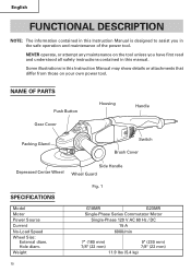
NAME OF PARTS Push Button Gear Cover Housing Handle Packing Gland Switch Brush Cover Depressed Center Wheel Side Handle Wheel Guard SPECIFICATIONS Model Motor Power Source Current No-Load Speed Wheel Size: External diam. Weight Fig. 1 G18MR G23MR Single-Phase Series Commutator Motor Single-Phase 120 V AC 60 Hz / DC 15 A 6000/min 7" (180 mm) 7/8" (22 mm) 9" (230 mm) 7/8" (22 mm) 11.9 lbs (5.4 kg) 10 Some illustrations in this Instruction Manual may show details...
NAME OF PARTS Push Button Gear Cover Housing Handle Packing Gland Switch Brush Cover Depressed Center Wheel Side Handle Wheel Guard SPECIFICATIONS Model Motor Power Source Current No-Load Speed Wheel Size: External diam. Weight Fig. 1 G18MR G23MR Single-Phase Series Commutator Motor Single-Phase 120 V AC 60 Hz / DC 15 A 6000/min 7" (180 mm) 7/8" (22 mm) 9" (230 mm) 7/8" (22 mm) 11.9 lbs (5.4 kg) 10 Some illustrations in this Instruction Manual may show details...
Instruction Manual
Page 11
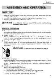
... booming noise. Check your work area is used, it may cause overheating, resulting in a serious hazard. 5. Power switch Ensure that the power source to a receptacle while the switch is in the ON position, the power tool will start operating immediately and can cause serious injury. 3. English ASSEMBLY AND OPERATION APPLICATIONS ⅜ Removal of casting fin and finishing of various type of steel, bronze and...
... booming noise. Check your work area is used, it may cause overheating, resulting in a serious hazard. 5. Power switch Ensure that the power source to a receptacle while the switch is in the ON position, the power tool will start operating immediately and can cause serious injury. 3. English ASSEMBLY AND OPERATION APPLICATIONS ⅜ Removal of casting fin and finishing of various type of steel, bronze and...
Instruction Manual
Page 12
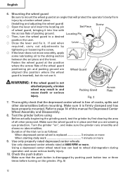
... Pin ⅜ Then, turn the wheel guard to mount the wheel guard at an angle that you are Wheel Guard aligned (the position where the wheel guard is disengaged by tightening or loosening the screw. ⅜ If the lever does not move smoothly, apply some lubricating oil to the sliding section between the set piece and the lever. Fasten the wheel guard at 6600 RPM or more 9. Test the grinder before mounting. Mounting the wheel guard Be...
... Pin ⅜ Then, turn the wheel guard to mount the wheel guard at an angle that you are Wheel Guard aligned (the position where the wheel guard is disengaged by tightening or loosening the screw. ⅜ If the lever does not move smoothly, apply some lubricating oil to the sliding section between the set piece and the lever. Fasten the wheel guard at 6600 RPM or more 9. Test the grinder before mounting. Mounting the wheel guard Be...
Instruction Manual
Page 13
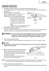
... grain size. Adjust operation to desired finish For a fine finish, decrease pressure by lifting the grinder 15° to the "on " (Fig. 3) While holding onto the grinder. 2. English GRINDER OPERATION 1. Switch ON: Push the locking button forward and then press the switch lever. Use light grinding pressure There is most suitable for heavy grinding of steel and other types of materials. 6. Use only the edge of the depressed center wheel. It...
... grain size. Adjust operation to desired finish For a fine finish, decrease pressure by lifting the grinder 15° to the "on " (Fig. 3) While holding onto the grinder. 2. English GRINDER OPERATION 1. Switch ON: Push the locking button forward and then press the switch lever. Use light grinding pressure There is most suitable for heavy grinding of steel and other types of materials. 6. Use only the edge of the depressed center wheel. It...
Instruction Manual
Page 14
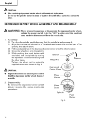
CAUTION: Depressed Center Wheel G Tighten the wheel nut securely and confirm that the spindle is in Fig. 5. Wheel Washer 2. DEPRESSED CENTER WHEEL ASSEMBLY AND DISASSEMBLY WARNING: Never attempt to a complete stop. Wheel Nut Tighten Tighten the wheel nut by turning Wrench the depressed center wheel slowly with the other hand. Disassembly To remove the depressed center wheel, simply reverse the above-mentioned procedure. Wheel Guard Spindle Fig. 5 Push Button 14 Assembly (1) Turn the disc grinder upsidedown so that the depressed...
CAUTION: Depressed Center Wheel G Tighten the wheel nut securely and confirm that the spindle is in Fig. 5. Wheel Washer 2. DEPRESSED CENTER WHEEL ASSEMBLY AND DISASSEMBLY WARNING: Never attempt to a complete stop. Wheel Nut Tighten Tighten the wheel nut by turning Wrench the depressed center wheel slowly with the other hand. Disassembly To remove the depressed center wheel, simply reverse the above-mentioned procedure. Wheel Guard Spindle Fig. 5 Push Button 14 Assembly (1) Turn the disc grinder upsidedown so that the depressed...

Instruction Manual
Page 15
... switch power OFF and disconnect the plug from the receptacle during maintenance and inspection. Confirm that there is a crack or a transformation in excess of the wear limit will damage the motor. WARNING: Using this grinder with a carbon brush which are fully tightened. Replace the carbon brush with loosened screws is no crack or any of carbon brush 61 0.26" (6.5mm) 0.89" (22.5mm) Fig. 6 Carbon Brush Spring Brush Holder Fig. 7 15...
... switch power OFF and disconnect the plug from the receptacle during maintenance and inspection. Confirm that there is a crack or a transformation in excess of the wear limit will damage the motor. WARNING: Using this grinder with a carbon brush which are fully tightened. Replace the carbon brush with loosened screws is no crack or any of carbon brush 61 0.26" (6.5mm) 0.89" (22.5mm) Fig. 6 Carbon Brush Spring Brush Holder Fig. 7 15...

Instruction Manual
Page 16
... a HITACHI AUTHORIZED SERVICE CENTER, ONLY. 6. Accordingly, some parts (i.e. Remove the edge of the spring toward the outside of the brush holder. (3) Remove the end of the pig-tail on the carbon brush from normal use. English (2) Use the auxiliary hexagonal wrench or small screwdriver to the head of the carbon brush. (4) Mount the tail cover and tighten the D4 tapping screw. 5. Service and repairs All quality power tools will be used, all service and repairs must be changed without...
... a HITACHI AUTHORIZED SERVICE CENTER, ONLY. 6. Accordingly, some parts (i.e. Remove the edge of the spring toward the outside of the brush holder. (3) Remove the end of the pig-tail on the carbon brush from normal use. English (2) Use the auxiliary hexagonal wrench or small screwdriver to the head of the carbon brush. (4) Mount the tail cover and tighten the D4 tapping screw. 5. Service and repairs All quality power tools will be used, all service and repairs must be changed without...
Instruction Manual
Page 17
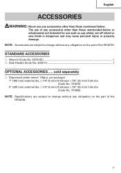
... part of the HITACHI. 17 English ACCESSORIES WARNING: Never use any accessories other than those mentioned below or attachments not intended for use of any accessories other than those mentionded below . NOTE: Accessories are subject to change without any obligation on the part of the HITACHI. sold separately ⅜ Depressed center wheel (10pcs. STANDARD ACCESSORIES ⅜ Wrench (Code No. 937913Z 1 ⅜ Side Handle (Code No. 322411 1 OPTIONAL ACCESSORIES...
... part of the HITACHI. 17 English ACCESSORIES WARNING: Never use any accessories other than those mentioned below or attachments not intended for use of any accessories other than those mentionded below . NOTE: Accessories are subject to change without any obligation on the part of the HITACHI. sold separately ⅜ Depressed center wheel (10pcs. STANDARD ACCESSORIES ⅜ Wrench (Code No. 937913Z 1 ⅜ Side Handle (Code No. 322411 1 OPTIONAL ACCESSORIES...
Parts List
Page 1
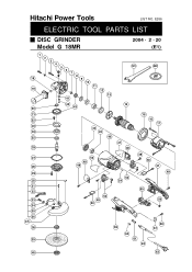
E266 ELECTRIC TOOL PARTS LIST DISC GRINDER Model G 18MR 2004 • 2 • 20 (E1) 1 2 3 4 5 6 7 8 18 9 10 11 19 12 13 41 42 20 43 21 22 23 44 24 45 25 46 26 501 14 47 48 502 15 16 17 27 28 29 30 31 32 33 34 35 36 37 38 39 52 48 49 53 49 50 53 54 49 50 51 49 55 56 59 60 61 62 58 57 40 63 Hitachi Power Tools LIST NO.
E266 ELECTRIC TOOL PARTS LIST DISC GRINDER Model G 18MR 2004 • 2 • 20 (E1) 1 2 3 4 5 6 7 8 18 9 10 11 19 12 13 41 42 20 43 21 22 23 44 24 45 25 46 26 501 14 47 48 502 15 16 17 27 28 29 30 31 32 33 34 35 36 37 38 39 52 48 49 53 49 50 53 54 49 50 51 49 55 56 59 60 61 62 58 57 40 63 Hitachi Power Tools LIST NO.
Parts List
Page 2
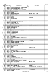
... FELT PACKING (B) SPINDLE SPINDLE SEAL PLATE 1 1 1 1 FOR USA, CAN 1 28 320-227 PACKING GLAND 1 29 994-192 HEX. BOLT (W/FLANGE) M5X16 4 30 311-492 LABEL 1 31 321-546 SET PIN 1 32 321-545 LEVER 1 33 306-887 BOLT M8X22 1 34 949-457 SPRING WASHER M8 (10 PCS.) 1 35 321-544 SET PIECE 1 36 673-489 RETAINING RING (E-TYPE) FOR D5 SHAFT...
... FELT PACKING (B) SPINDLE SPINDLE SEAL PLATE 1 1 1 1 FOR USA, CAN 1 28 320-227 PACKING GLAND 1 29 994-192 HEX. BOLT (W/FLANGE) M5X16 4 30 311-492 LABEL 1 31 321-546 SET PIN 1 32 321-545 LEVER 1 33 306-887 BOLT M8X22 1 34 949-457 SPRING WASHER M8 (10 PCS.) 1 35 321-544 SET PIECE 1 36 673-489 RETAINING RING (E-TYPE) FOR D5 SHAFT...
Parts List
Page 3
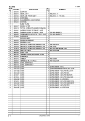
... CARBON BRUSH (AUTO STOP TYPE) (1 PAIR) 1 FOR NZL, EUROPE 51 322-546 HANDLE (B) 1 52 HITACHI LABEL 1 53 322-323 BRUSH HOLDER SET 2 54 946-362 BEARING LOCK 1 * 55 320-239 SWITCH (2P PILLAR TYPE) W/SAFETY LOCK 1 OFF/ON LOCK * 55 320-238 SWITCH (2P PILLAR TYPE) W/SAFETY LOCK 1 OFF LOCK * 55 322-614 SWITCH (2P PILLAR TYPE) W/SAFETY LOCK 1 INCLUD. 56 FOR USA, CAN * 56 322-549 SWITCH COVER 1 FOR USA, CAN 57 960-266 CORD...
... CARBON BRUSH (AUTO STOP TYPE) (1 PAIR) 1 FOR NZL, EUROPE 51 322-546 HANDLE (B) 1 52 HITACHI LABEL 1 53 322-323 BRUSH HOLDER SET 2 54 946-362 BEARING LOCK 1 * 55 320-239 SWITCH (2P PILLAR TYPE) W/SAFETY LOCK 1 OFF/ON LOCK * 55 320-238 SWITCH (2P PILLAR TYPE) W/SAFETY LOCK 1 OFF LOCK * 55 322-614 SWITCH (2P PILLAR TYPE) W/SAFETY LOCK 1 INCLUD. 56 FOR USA, CAN * 56 322-549 SWITCH COVER 1 FOR USA, CAN 57 960-266 CORD...

Parts List
Page 4
... USA, CAN * 606 949-656 HEX. BOLT M8X20 (10 PCS.) 2 FOR USA, CAN * 607 949-457 SPRING WASHER M8 (10 PCS.) 2 FOR USA, CAN --- 4 --- * ALTERNATIVE PARTS Printed in Japan 2 -- 04 (040220N) CODE NO. DESCRIPTION 501 937-913Z WRENCH * 502 937-917Z WHEEL NUT (B) NO. SOCKET HD. DESCRIPTION NO. STANDARD ACCESSORIES ITEM NO. CODE NO. USED 1 1 FOR NZL REMARKS G 18MR OPTIONAL...
... USA, CAN * 606 949-656 HEX. BOLT M8X20 (10 PCS.) 2 FOR USA, CAN * 607 949-457 SPRING WASHER M8 (10 PCS.) 2 FOR USA, CAN --- 4 --- * ALTERNATIVE PARTS Printed in Japan 2 -- 04 (040220N) CODE NO. DESCRIPTION 501 937-913Z WRENCH * 502 937-917Z WHEEL NUT (B) NO. SOCKET HD. DESCRIPTION NO. STANDARD ACCESSORIES ITEM NO. CODE NO. USED 1 1 FOR NZL REMARKS G 18MR OPTIONAL...

