
Instruction Manual
Page 3
... safe for you first confirm that result from power tool operation and maintenance are identified by observing appropriate safety procedures. NOTE emphasizes essential information. 3 Basic safety precautions are outlined in the "SAFETY" section of the operating instructions, safety precautions and warnings in the Instruction Manual before it occurs, and by WARNINGS on the power tool and in this power tool in the sections which contain the...
... safe for you first confirm that result from power tool operation and maintenance are identified by observing appropriate safety procedures. NOTE emphasizes essential information. 3 Basic safety precautions are outlined in the "SAFETY" section of the operating instructions, safety precautions and warnings in the Instruction Manual before it occurs, and by WARNINGS on the power tool and in this power tool in the sections which contain the...

Instruction Manual
Page 4
... operating a power tool. Personal Safety (1) Stay alert, watch what you to follow all instructions. A moment of inattention while operating power tools may ignite the dust of electric shock. 3. Do not change the plug in moving parts. (3) Avoid accidental starting. Water entering a power tool will fit in a polarized outlet only one blade is grounded. (3) Don't expose power tools to install a polarized outlet. Never use an outdoor extension cord marked "W-A" or "W". Keep your work...
... operating a power tool. Personal Safety (1) Stay alert, watch what you to follow all instructions. A moment of inattention while operating power tools may ignite the dust of electric shock. 3. Do not change the plug in moving parts. (3) Avoid accidental starting. Water entering a power tool will fit in a polarized outlet only one blade is grounded. (3) Don't expose power tools to install a polarized outlet. Never use an outdoor extension cord marked "W-A" or "W". Keep your work...
Instruction Manual
Page 5
... practical way to secure and support the workpiece to loss of the tool may affect the tools operation. Holding the work by qualified repair personnel. Such preventive safety measures reduce the risk of starting the tool accidentally. (5) Store idle tools out of reach of the tool in the Maintenance section of electric shock or injury. 5 English (4) Remove adjusting keys or wrenches before using. Follow instructions in unexpected situations. (6) Use safety equipment.
... practical way to secure and support the workpiece to loss of the tool may affect the tools operation. Holding the work by qualified repair personnel. Such preventive safety measures reduce the risk of starting the tool accidentally. (5) Store idle tools out of reach of the tool in the Maintenance section of electric shock or injury. 5 English (4) Remove adjusting keys or wrenches before using. Follow instructions in unexpected situations. (6) Use safety equipment.

Instruction Manual
Page 6
... motor air vent clean. Check for cutting tree limbs or logs. 6. Contact with its operation or unauthorized personnel. 8. If maintenance or servicing requires the removal of a guard or safety feature, be securely mounted to replace the guard or safety feature before resuming operation of the tool "live " wire will result in the Instruction Manual. 7. Don't force small tool or attachment to the instructions provided herein. Keep all screws, bolts, and plates tightly mounted...
... motor air vent clean. Check for cutting tree limbs or logs. 6. Contact with its operation or unauthorized personnel. 8. If maintenance or servicing requires the removal of a guard or safety feature, be securely mounted to replace the guard or safety feature before resuming operation of the tool "live " wire will result in the Instruction Manual. 7. Don't force small tool or attachment to the instructions provided herein. Keep all screws, bolts, and plates tightly mounted...

Instruction Manual
Page 7
... damage and crack plastic parts. ALWAYS wear eye protectors during operation. 18. Do not wipe them with this tool V volts Hz hertz A amperes no load speed W watt Class II Construction ---/min .... no .......... Definitions for symbols used on this tool, you are any buried object such as an underground wiring. English 15. Carefully handle power tools. Touching these active wiring or electric cable with such...
... damage and crack plastic parts. ALWAYS wear eye protectors during operation. 18. Do not wipe them with this tool V volts Hz hertz A amperes no load speed W watt Class II Construction ---/min .... no .......... Definitions for symbols used on this tool, you are any buried object such as an underground wiring. English 15. Carefully handle power tools. Touching these active wiring or electric cable with such...

Instruction Manual
Page 8
... THESE INSTRUCTIONS AND MAKE THEM AVAILABLE TO OTHER USERS OF THIS TOOL! 8 "Double insulation " means that two physically separated insulation systems have been used to insulate the electrically conductive materials connected to the power supply from the outer frame handled by the operator. English DOUBLE INSULATION FOR SAFER OPERATION To ensure safer operation of this power tool, and only genuine HITACHI replacement parts should be installed...
... THESE INSTRUCTIONS AND MAKE THEM AVAILABLE TO OTHER USERS OF THIS TOOL! 8 "Double insulation " means that two physically separated insulation systems have been used to insulate the electrically conductive materials connected to the power supply from the outer frame handled by the operator. English DOUBLE INSULATION FOR SAFER OPERATION To ensure safer operation of this power tool, and only genuine HITACHI replacement parts should be installed...
Instruction Manual
Page 9
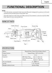
... Instruction Manual may show details or attachments that differ from those on your own power tool NAME OF PARTS Holder Sleeve Base Front Cover Brush Cap Blade Base Lever Push Button Housing Change Lever Dial Fig. 1 Switch Trigger Handle SPECIFICATIONS Motor Power Source Current Capacity No-Load Speed Stroke Weight (without cord) Single-Phase, Series Commutator Motor Single-Phase, 120 V AC 60 Hz 11 A Mild Steel Pipe: O.D. 5" (130 mm) Vinyl Chloride Pipe: O.D. 5" (130 mm) Wood: Depth...
... Instruction Manual may show details or attachments that differ from those on your own power tool NAME OF PARTS Holder Sleeve Base Front Cover Brush Cap Blade Base Lever Push Button Housing Change Lever Dial Fig. 1 Switch Trigger Handle SPECIFICATIONS Motor Power Source Current Capacity No-Load Speed Stroke Weight (without cord) Single-Phase, Series Commutator Motor Single-Phase, 120 V AC 60 Hz 11 A Mild Steel Pipe: O.D. 5" (130 mm) Vinyl Chloride Pipe: O.D. 5" (130 mm) Wood: Depth...

Instruction Manual
Page 10
Power switch Ensure that the work area is far away from the power source, use of a wrench or other tools. (1) Turn on and off and the power cord unplugged to make appropriate repairs. WARNING: Damaged cord must be utilized conforms to be repaired. Confirming condition of the environment: Confirm that the switch is in the ON position, the power tool will start operating immediately and can jump out of...
Power switch Ensure that the work area is far away from the power source, use of a wrench or other tools. (1) Turn on and off and the power cord unplugged to make appropriate repairs. WARNING: Damaged cord must be utilized conforms to be repaired. Confirming condition of the environment: Confirm that the switch is in the ON position, the power tool will start operating immediately and can jump out of...

Instruction Manual
Page 11
.... Thereafter, turn off the switch and unplug the power cord. (Fig. 2) CAUTION: Be absolutely sure to keep the switch turned off and the power cord unplugged to the arrow marked on and off the switching trigger several times so that the blade is hot and can jump out of the saw blade immediately after use. If the blade does't fall out by hand. Pulling other parts of...
.... Thereafter, turn off the switch and unplug the power cord. (Fig. 2) CAUTION: Be absolutely sure to keep the switch turned off and the power cord unplugged to the arrow marked on and off the switching trigger several times so that the blade is hot and can jump out of the saw blade immediately after use. If the blade does't fall out by hand. Pulling other parts of...
Instruction Manual
Page 12
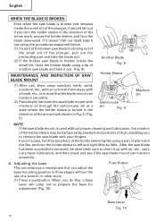
... the periphery of the holder sleeve lightly using a tip of another saw blade and take it out. (Fig. 8) MAINTENANCE AND INSPECTION OF SAW BLADE MOUNT (1) After use, blow away sawdust, earth, sand, moisture, etc., with air or brush them away with a brush, etc., to ensure that can adjust the base mounting position in three stages without proper cleaning and lubrication, the rotation of the holder sleeve may be...
... the periphery of the holder sleeve lightly using a tip of another saw blade and take it out. (Fig. 8) MAINTENANCE AND INSPECTION OF SAW BLADE MOUNT (1) After use, blow away sawdust, earth, sand, moisture, etc., with air or brush them away with a brush, etc., to ensure that can adjust the base mounting position in three stages without proper cleaning and lubrication, the rotation of the holder sleeve may be...
Instruction Manual
Page 13
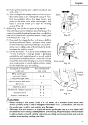
.... 11 Base Lever Fig. 12 Dial Scale Fig. 13 Switch Trigger CAUTION: ⅜ When cutting at low speed (scale of 1 - 2), never cut position. Adjusting the blade reciprocating speed This unit has a built-in selecting the suitable speed for hard materials such as sudden stops during cutting operation. 13 Properly adjust the saw blade either both by pulling a switching trigger or turning a dial. (Fig. 13) (1) If you pull the trigger further in the base lever with nails...
.... 11 Base Lever Fig. 12 Dial Scale Fig. 13 Switch Trigger CAUTION: ⅜ When cutting at low speed (scale of 1 - 2), never cut position. Adjusting the blade reciprocating speed This unit has a built-in selecting the suitable speed for hard materials such as sudden stops during cutting operation. 13 Properly adjust the saw blade either both by pulling a switching trigger or turning a dial. (Fig. 13) (1) If you pull the trigger further in the base lever with nails...
Instruction Manual
Page 14
.... ⅜ During use . ⅜ Do not remove the front cover (refer to make curved or clean cuts. ⅜ Dust and dirt accumulated on the switch. Straight cutting should normally be selected with your finger on the change lever. A sudden startup can perform swing cutting by setting the change lever section. Be sure to hold the body from the top of the saw blade forcibly bites...
.... ⅜ During use . ⅜ Do not remove the front cover (refer to make curved or clean cuts. ⅜ Dust and dirt accumulated on the switch. Straight cutting should normally be selected with your finger on the change lever. A sudden startup can perform swing cutting by setting the change lever section. Be sure to hold the body from the top of the saw blade forcibly bites...
Instruction Manual
Page 15
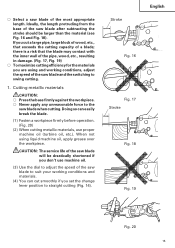
... any unreasonable force to the saw blade after subtracting the stroke should be drastically shortened if you set the change lever position to straight cutting (Fig. 14). If you cut smoothly if you don't use proper machine oil (turbine oil, etc.). ⅜ Select a saw blade to suit your working conditions, adjust the speed of the saw blade and the switching to swing cutting. 1. Doing so can cut a large pipe, large block...
... any unreasonable force to the saw blade after subtracting the stroke should be drastically shortened if you set the change lever position to straight cutting (Fig. 14). If you cut smoothly if you don't use proper machine oil (turbine oil, etc.). ⅜ Select a saw blade to suit your working conditions, adjust the speed of the saw blade and the switching to swing cutting. 1. Doing so can cut a large pipe, large block...
Instruction Manual
Page 16
... recommend for the saw blade is set to swing cutting (Fig. 15). Use the saw blade that the workpiece is fastened firmly before beginning. (Fig. 21) (2) You can cut efficiently if the change lever position is as short and thick as illustrated in Page 19 for this tool, you can cut efficiently if the speed of the saw blade since it is set to straight cutting (Fig. 14...
... recommend for the saw blade is set to swing cutting (Fig. 15). Use the saw blade that the workpiece is fastened firmly before beginning. (Fig. 21) (2) You can cut efficiently if the change lever position is as short and thick as illustrated in Page 19 for this tool, you can cut efficiently if the speed of the saw blade since it is set to straight cutting (Fig. 14...

Instruction Manual
Page 17
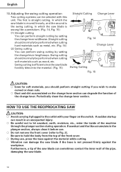
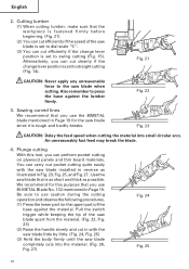
If you apply any unreasonable force to the saw blade during the cutting operation, the blade can easily be damaged when it collides with the material. ⅜ Make absolutely sure that you do so, the blade can easily damage the blade. ⅜ Never pull the switch trigger while the tip of the saw blade tip is pressed against the material. English Fig. 26 Fig. 27 17 This can easily be damaged. If you cut slowly while holding the body firmly. CAUTION: ⅜ Avoid plunge cutting for metallic materials.
If you apply any unreasonable force to the saw blade during the cutting operation, the blade can easily be damaged when it collides with the material. ⅜ Make absolutely sure that you do so, the blade can easily damage the blade. ⅜ Never pull the switch trigger while the tip of the saw blade tip is pressed against the material. English Fig. 26 Fig. 27 17 This can easily be damaged. If you cut slowly while holding the body firmly. CAUTION: ⅜ Avoid plunge cutting for metallic materials.

Instruction Manual
Page 18
... brush carbon brush is noted. 2. English MAINTENANCE AND INSPECTION WARNING: Be sure to switch power OFF and disconnect the plug from normal use of Hitachi Power Tools must be carried out by a HITACHI AUTHORIZED SERVICE CENTER, ONLY. 7. At that only authorized replacement parts will stop No. Fig. 28 NOTE: Use HITACHI carbon brush No. 43 indicated in reduced cutting efficiency and may cause overloading of the screws be easily removed. 6. WARNING: Using this reciprocating saw...
... brush carbon brush is noted. 2. English MAINTENANCE AND INSPECTION WARNING: Be sure to switch power OFF and disconnect the plug from normal use of Hitachi Power Tools must be carried out by a HITACHI AUTHORIZED SERVICE CENTER, ONLY. 7. At that only authorized replacement parts will stop No. Fig. 28 NOTE: Use HITACHI carbon brush No. 43 indicated in reduced cutting efficiency and may cause overloading of the screws be easily removed. 6. WARNING: Using this reciprocating saw...

Instruction Manual
Page 19
In the operation and maintenance of power tools, the safety regulations and standards prescribed in each country must be changed without prior notice. 19 Accordingly, some parts (i.e. MODIFICATIONS: Hitachi Power Tools are constantly being improved and modified to incorporate the latest technological advancements. code numbers and/or design) may be observed. English Authorized Service Center when requesting repair or other maintenance.
In the operation and maintenance of power tools, the safety regulations and standards prescribed in each country must be changed without prior notice. 19 Accordingly, some parts (i.e. MODIFICATIONS: Hitachi Power Tools are constantly being improved and modified to incorporate the latest technological advancements. code numbers and/or design) may be observed. English Authorized Service Center when requesting repair or other maintenance.

Parts List
Page 2
... HOLDER PIN 1 SPRING (B) 1 HOLDER SLEEVE (A) 1 HOLDER SLEEVE (B) 1 STEEL BALL D4.76 (10 PCS.) 2 HOLDER SLEEVE (C) 1 GUIDE WASHER 1 DUST WASHER 1 SPRING (A) 1 WASHER (D) 1 THRUST BEARING 1 BASE 1 TAPPING SCREW D4X8 1 HOLDER SPRING 1 BASE LEVER 1 FRONT COVER (B) 1 PUSHING BUTTON 1 SPRING (C) 1 FT-MACHINE SCREW M4X6 2 FELT COVER 1 GEAR COVER 1 PLUNGER (A) SET 1 INCLUD.10 INNER COVER (A) 1 CHANGE SHAFT 1 O-RING (1AP-10) 2 RETAINING RING (E-TYPE) FOR D7 SHAFT 1 BRUSH CAP 2 CARBON BRUSH (1 PAIR) 2 BRUSH HOLDER 2 HOUSING (GREEN) 1 NAME PLATE...
... HOLDER PIN 1 SPRING (B) 1 HOLDER SLEEVE (A) 1 HOLDER SLEEVE (B) 1 STEEL BALL D4.76 (10 PCS.) 2 HOLDER SLEEVE (C) 1 GUIDE WASHER 1 DUST WASHER 1 SPRING (A) 1 WASHER (D) 1 THRUST BEARING 1 BASE 1 TAPPING SCREW D4X8 1 HOLDER SPRING 1 BASE LEVER 1 FRONT COVER (B) 1 PUSHING BUTTON 1 SPRING (C) 1 FT-MACHINE SCREW M4X6 2 FELT COVER 1 GEAR COVER 1 PLUNGER (A) SET 1 INCLUD.10 INNER COVER (A) 1 CHANGE SHAFT 1 O-RING (1AP-10) 2 RETAINING RING (E-TYPE) FOR D7 SHAFT 1 BRUSH CAP 2 CARBON BRUSH (1 PAIR) 2 BRUSH HOLDER 2 HOUSING (GREEN) 1 NAME PLATE...

Parts List
Page 3
... 500-434Z DESCRIPTION SWING RAIL SWING ROLLER PIN D6 HITACHI LABEL BALL BEARING 6003DDCMPS2S SUB SHAFT BEARING COVER (B) MACHINE SCREW M4X10 (10 PCS.) RETAINING RING FOR D17 SHAFT RECIPRO PLATE BALL BEARING 6003VVCMPS2L RETAINING RING FOR D35 HOLE (10 PCS.) SECOND SHAFT (A) GEAR BALL BEARING 608VVC2PS2L BALL BEARING 6001VVCMPS2L BEARING COVER FLAT HD. PARTS ITEM NO. USED 2 REMARKS 2 1 1 1 1 1 2 1 1 2 1 1 1 2 1 1 2 1 INCLUD...
... 500-434Z DESCRIPTION SWING RAIL SWING ROLLER PIN D6 HITACHI LABEL BALL BEARING 6003DDCMPS2S SUB SHAFT BEARING COVER (B) MACHINE SCREW M4X10 (10 PCS.) RETAINING RING FOR D17 SHAFT RECIPRO PLATE BALL BEARING 6003VVCMPS2L RETAINING RING FOR D35 HOLE (10 PCS.) SECOND SHAFT (A) GEAR BALL BEARING 608VVC2PS2L BALL BEARING 6001VVCMPS2L BEARING COVER FLAT HD. PARTS ITEM NO. USED 2 REMARKS 2 1 1 1 1 1 2 1 1 2 1 1 1 2 1 1 2 1 INCLUD...
Parts List
Page 4
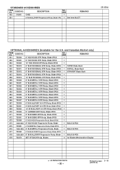
... Item No.677 CR 13VA OPTIONAL ACCESSORIES [Available for Blades Merchandiser Display * : ALTERNATIVE PARTS --- 35 --- USED 1 REMARKS 551 8" BI-M ALLPURP Progressive Recip. Blade 5PCS 1 SCROLL Blade Back 656 725312 6" BI-M WOODNAIL 6TPI Recip. Blade 5PCS 1 668 725331 9" BI-M ALLPURP 10/14TPI Recip. Blade 5PCS NO. Blade 5PCS 1 676 725361B50 6" BI-M METAL Progressive Recip. CODE NO. 651 725300 DESCRIPTION 6" HCS WOOD...
... Item No.677 CR 13VA OPTIONAL ACCESSORIES [Available for Blades Merchandiser Display * : ALTERNATIVE PARTS --- 35 --- USED 1 REMARKS 551 8" BI-M ALLPURP Progressive Recip. Blade 5PCS 1 SCROLL Blade Back 656 725312 6" BI-M WOODNAIL 6TPI Recip. Blade 5PCS 1 668 725331 9" BI-M ALLPURP 10/14TPI Recip. Blade 5PCS NO. Blade 5PCS 1 676 725361B50 6" BI-M METAL Progressive Recip. CODE NO. 651 725300 DESCRIPTION 6" HCS WOOD...

