Instruction Manual
Page 4
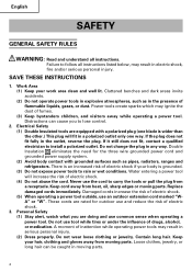
... cords immediately. These cords are rated for the three wire grounded power cord and grounded power supply system. (2) Avoid body contact with a polarized plug (one blade is grounded. (3) Do not expose power tools to follow all instructions. Power tools create sparks which may result in serious personal injury. (2) Dress properly. Distractions...
... cords immediately. These cords are rated for the three wire grounded power cord and grounded power supply system. (2) Avoid body contact with a polarized plug (one blade is grounded. (3) Do not expose power tools to follow all instructions. Power tools create sparks which may result in serious personal injury. (2) Dress properly. Distractions...
Instruction Manual
Page 6
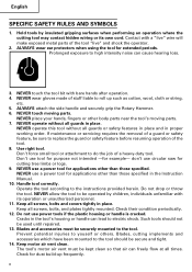
...been mounted to the tool should not be securely mounted to be secure and tight. 14. Keep motor air vent clean. don't use circular saw for extended periods. Do not drop or throw the tool. Keep all screws, bolts and covers tightly in place. The tool's motor air .... NEVER use a power tool for example- NEVER use a power tool for dust build-up such as cotton, wool, cloth or string, etc. 5. Handle tool correctly. Blades and accessories must be sure to electric shock. Use right tool. NEVER touch the tool bit with a "live " and shock the operator. 2. NEVER wear...
...been mounted to the tool should not be securely mounted to be secure and tight. 14. Keep motor air vent clean. don't use circular saw for extended periods. Do not drop or throw the tool. Keep all screws, bolts and covers tightly in place. The tool's motor air .... NEVER use a power tool for example- NEVER use a power tool for dust build-up such as cotton, wool, cloth or string, etc. 5. Handle tool correctly. Blades and accessories must be sure to electric shock. Use right tool. NEVER touch the tool bit with a "live " and shock the operator. 2. NEVER wear...
Instruction Manual
Page 7
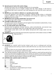
...19. Don't leave tool until it may burn out. 16. This Jig Saw employs a high-power motor. Always operate the power tool so that ... otherwise appears defective, stop . 18. Operate power tools at low speed, an extra load is used on its nameplate. Touching these active...minute .......... Carefully handle power tools. Do not wipe plastic parts with such solvents. ALWAYS wear eye protection that the blade is defective or ... inadvertently, it comes to the motor which is not caught by a Hitachi authorized service center. 17. Wipe plastic parts with a soft cloth lightly...
...19. Don't leave tool until it may burn out. 16. This Jig Saw employs a high-power motor. Always operate the power tool so that ... otherwise appears defective, stop . 18. Operate power tools at low speed, an extra load is used on its nameplate. Touching these active...minute .......... Carefully handle power tools. Do not wipe plastic parts with such solvents. ALWAYS wear eye protection that the blade is defective or ... inadvertently, it comes to the motor which is not caught by a Hitachi authorized service center. 17. Wipe plastic parts with a soft cloth lightly...

Instruction Manual
Page 9
.... Some illustrations in this manual. NAME OF PARTS Stopper Switch Trigger Lever Plunger SPECIFICATIONS Motor Power Source Capacity Current No-load speed Stroke Min. cutting radius Weight Housing Base Change knob Blade Fig. 1 Single-Phase, Series Commutator Motor Single-Phase, 120V AC 60Hz Wood 4-5/16" (110mm) Mind steel 3/8" (10mm) 5.8A 850 - 3000...
.... Some illustrations in this manual. NAME OF PARTS Stopper Switch Trigger Lever Plunger SPECIFICATIONS Motor Power Source Capacity Current No-load speed Stroke Min. cutting radius Weight Housing Base Change knob Blade Fig. 1 Single-Phase, Series Commutator Motor Single-Phase, 120V AC 60Hz Wood 4-5/16" (110mm) Mind steel 3/8" (10mm) 5.8A 850 - 3000...
Instruction Manual
Page 10
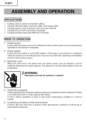
... be kept as short as phenol resin and vinyl chloride ⅜ Cutting thin and soft construction materials ⅜ Cutting stainless steel plate (With No. 97 blade) PRIOR TO OPERATION 1. Power switch Ensure that the switch is connected to prescribed precautions. 10 If the plug is in the ON position, the power...
... be kept as short as phenol resin and vinyl chloride ⅜ Cutting thin and soft construction materials ⅜ Cutting stainless steel plate (With No. 97 blade) PRIOR TO OPERATION 1. Power switch Ensure that the switch is connected to prescribed precautions. 10 If the plug is in the ON position, the power...
Instruction Manual
Page 11
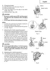
... the lever when plunger is set to "1", the jig saw operates at the minimum speed (850 /min.). When the dial set to "5", the jig saw operates at the maximum speed (3000/min.). English Blade Blade holder Lever Fig. 3 Blade Blade holder Fig. 4 Blade Roller Blade Roller Fig. 5 Dial Fig. 6 11 CAUTION: ⅷ At low speed (dial setting: 1 or 2) do not cut and working...
... the lever when plunger is set to "1", the jig saw operates at the minimum speed (850 /min.). When the dial set to "5", the jig saw operates at the maximum speed (3000/min.). English Blade Blade holder Lever Fig. 3 Blade Blade holder Fig. 4 Blade Roller Blade Roller Fig. 5 Dial Fig. 6 11 CAUTION: ⅷ At low speed (dial setting: 1 or 2) do not cut and working...
Instruction Manual
Page 12
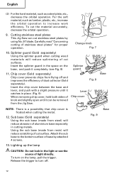
... with a slight pressure until it catches in the light or see Fig. 8) 11. Using the sub base (made from the Jig Saw. Cutting stainless steel plates This Jig Saw can be removed from steel) will reduce splintering of light directly. Change knob Fig. 7 Splinter guard Fig. 8 Lever Chip cover...Fig. 9 Base CAUTION: Do not look in place. (Fig. 9) When removing chip cover, hold both sides of base by using No. 97 blade. English (2) For the hard material, such as lumber, plastic, etc., increase the orbital operation to increase work efficiency. To turn off and improves...
... with a slight pressure until it catches in the light or see Fig. 8) 11. Using the sub base (made from the Jig Saw. Cutting stainless steel plates This Jig Saw can be removed from steel) will reduce splintering of light directly. Change knob Fig. 7 Splinter guard Fig. 8 Lever Chip cover...Fig. 9 Base CAUTION: Do not look in place. (Fig. 9) When removing chip cover, hold both sides of base by using No. 97 blade. English (2) For the hard material, such as lumber, plastic, etc., increase the orbital operation to increase work efficiency. To turn off and improves...
Instruction Manual
Page 13
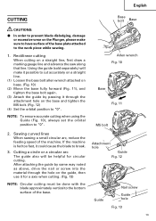
...a axis when cutting. (Fig. 13) NOTE: Circular cutting must be done with the blade approximately vertical to the bottom surface of the base. Sawing curved lines When sawing a small circular arc, reduce the feeding speed of the base plate attached to break. 3. After attaching the guide by passing it through... the hole on the guide, then use it could cause the blade to the work piece while sawing. 1. NOTE: To...
...a axis when cutting. (Fig. 13) NOTE: Circular cutting must be done with the blade approximately vertical to the bottom surface of the base. Sawing curved lines When sawing a small circular arc, reduce the feeding speed of the base plate attached to break. 3. After attaching the guide by passing it through... the hole on the guide, then use it could cause the blade to the work piece while sawing. 1. NOTE: To...
Instruction Manual
Page 14
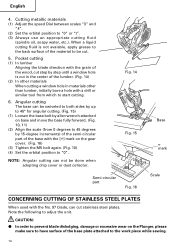
Note the following to the work piece while sawing. 14 CAUTION: ⅷ In order to prevent blade dislodging, damage or excessive wear on base and move the base fully forward. (Fig. 10, 11) (2) Align the scale (from which to "0" or "I". (3) Always...Fig. 15) (1) Loosen the base bolt by 15-degree increments) of the semi-circular part of the material to "0". English 4. Cutting metallic materials (1) Adjust the speed Dial between scales "3" and "4". (2) Set the orbital position to start cutting. 6. Fig. 14 Fig. 15 Semi-circular part Fig. 16 Base mark Scale CONCERNING ...
Note the following to the work piece while sawing. 14 CAUTION: ⅷ In order to prevent blade dislodging, damage or excessive wear on base and move the base fully forward. (Fig. 10, 11) (2) Align the scale (from which to "0" or "I". (3) Always...Fig. 15) (1) Loosen the base bolt by 15-degree increments) of the semi-circular part of the material to "0". English 4. Cutting metallic materials (1) Adjust the speed Dial between scales "3" and "4". (2) Set the orbital position to start cutting. 6. Fig. 14 Fig. 15 Semi-circular part Fig. 16 Base mark Scale CONCERNING ...
Instruction Manual
Page 15
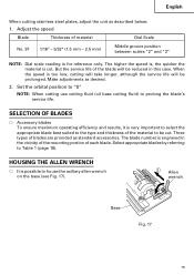
...Fig. 17 15 The higher the speed is, the quicker the material is engraved in this case. SELECTION OF BLADES ⅜ Accessory blades To ensure maximum operating efficiency and results, it is for reference only. Select appropriate blades by referring to house the axiliary ...allen wrench on the base (see Fig. 17). Adjust the speed Blade Thickness of material Dial Scale...
...Fig. 17 15 The higher the speed is, the quicker the material is engraved in this case. SELECTION OF BLADES ⅜ Accessory blades To ensure maximum operating efficiency and results, it is for reference only. Select appropriate blades by referring to house the axiliary ...allen wrench on the base (see Fig. 17). Adjust the speed Blade Thickness of material Dial Scale...
Instruction Manual
Page 18
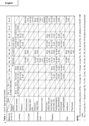
.... 11 No. 12 No. 15 No. 16 No. 21 No. 22 Thickness of No. 1 (Long), No. 1 ( Super Long), No. 21, No. 22 and No. 41 blades is 3-15/16" (100 mm). ⅜ No. 1 (Long), No. 1 ( Super Long), No. 11, No. 12, No. 15, No. 16, No. 21, No. 22 and No.... 97 blades are sold separately. Vinyl chloride, acryl resin, etc. English 18 Table 1 List of appropriate blades Material Blade to 63/64(25) 3/16-19/32 (5-15) 3/16-19/32 (5-15) 3/16-63/64 (5-25) Pulp Hardboard...
.... 11 No. 12 No. 15 No. 16 No. 21 No. 22 Thickness of No. 1 (Long), No. 1 ( Super Long), No. 21, No. 22 and No. 41 blades is 3-15/16" (100 mm). ⅜ No. 1 (Long), No. 1 ( Super Long), No. 11, No. 12, No. 15, No. 16, No. 21, No. 22 and No.... 97 blades are sold separately. Vinyl chloride, acryl resin, etc. English 18 Table 1 List of appropriate blades Material Blade to 63/64(25) 3/16-19/32 (5-15) 3/16-19/32 (5-15) 3/16-63/64 (5-25) Pulp Hardboard...
Instruction Manual
Page 19
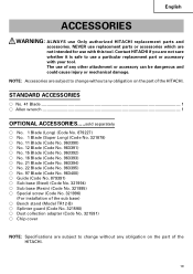
... No. 963394) ⅜ No. 22 Blade (Code No. 963395) ⅜ No. 97 Blade (Code No. 963400) ⅜ Guide (Code No. 879391) ⅜ Sub base (Steel) (Code No. 321994) ⅜ Sub base (Resin) (Code No. 321995) ⅜ Special screw (Code No. 321996) (For installation of the HITACHI. Contact HITACHI if you are subject to use...
... No. 963394) ⅜ No. 22 Blade (Code No. 963395) ⅜ No. 97 Blade (Code No. 963400) ⅜ Guide (Code No. 879391) ⅜ Sub base (Steel) (Code No. 321994) ⅜ Sub base (Resin) (Code No. 321995) ⅜ Special screw (Code No. 321996) (For installation of the HITACHI. Contact HITACHI if you are subject to use...
Parts List
Page 3
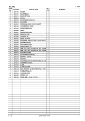
... PCS.) 1 REMARKS CJ 110MV 10 -- 05 * ALTERNATIVE PARTS --- 3 --- DESCRIPTION NO. SOCKET HD. BOLT M3X8 1 51 325-077 SEAL LOCK HEX. BOLT M3X6 1 52 325-076 BLADE HOLDER 1 53 325-073 PLUNGER HOLDER (B) 1 54 325-075 PACKING COVER 1 55 325-074 PACKING 1 56 315-500 MACHINE SCREW (W/WASHER) M4X8 (BLACK) 1 57 321... 325-066 ORBITAL CAM 1 44 957-540 WASHER (A) 1 45 325-061 GEAR HOLDER 1 46 673-489 RETAINING RING (E-TYPE) FOR D5 SHAFT 1 47 325-064 BLADE ROLLER 1 48 325-063 ROLLER HOLDER 1 49 325-062 NEEDLE ROLLER 1 50 325-241 SEAL LOCK HEX. CODE NO.
... PCS.) 1 REMARKS CJ 110MV 10 -- 05 * ALTERNATIVE PARTS --- 3 --- DESCRIPTION NO. SOCKET HD. BOLT M3X8 1 51 325-077 SEAL LOCK HEX. BOLT M3X6 1 52 325-076 BLADE HOLDER 1 53 325-073 PLUNGER HOLDER (B) 1 54 325-075 PACKING COVER 1 55 325-074 PACKING 1 56 315-500 MACHINE SCREW (W/WASHER) M4X8 (BLACK) 1 57 321... 325-066 ORBITAL CAM 1 44 957-540 WASHER (A) 1 45 325-061 GEAR HOLDER 1 46 673-489 RETAINING RING (E-TYPE) FOR D5 SHAFT 1 47 325-064 BLADE ROLLER 1 48 325-063 ROLLER HOLDER 1 49 325-062 NEEDLE ROLLER 1 50 325-241 SEAL LOCK HEX. CODE NO.
Parts List
Page 4
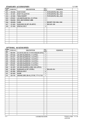
USED 601 963-400 JIG SAW BLADES NO. 97 FOR STAINLESS (5PCS.) 1 602 879-336 JIG SAW BLADES NO. 11 (5 PCS.) 1 603 879-337 JIG SAW BLADES NO. 12 (5 PCS.) 1 604 879-338 JIG SAW BLADES NO. 15 (5 PCS.) 1 605 879-339 JIG SAW BLADES NO. 16 (5 PCS.) 1 606 879-340 JIG SAW BLADES NO. 21 (5 PCS.) 1 607 879-341 JIG SAW BLADES NO. 22 (5 PCS.) 1 608 321-878 JIG SAW BLADES (LONG) 185L (3PCS...) 508 321-996 SPECIAL BOLT NO. DESCRIPTION * 501 325-096 CHIP COVER * 502 321-591 DUST COLLECTOR * 503 321-590 TABLE INSERT 504 879-357 JIG SAW BLADE NO. 41 (5 PCS.) 505 944-458 HEX.
USED 601 963-400 JIG SAW BLADES NO. 97 FOR STAINLESS (5PCS.) 1 602 879-336 JIG SAW BLADES NO. 11 (5 PCS.) 1 603 879-337 JIG SAW BLADES NO. 12 (5 PCS.) 1 604 879-338 JIG SAW BLADES NO. 15 (5 PCS.) 1 605 879-339 JIG SAW BLADES NO. 16 (5 PCS.) 1 606 879-340 JIG SAW BLADES NO. 21 (5 PCS.) 1 607 879-341 JIG SAW BLADES NO. 22 (5 PCS.) 1 608 321-878 JIG SAW BLADES (LONG) 185L (3PCS...) 508 321-996 SPECIAL BOLT NO. DESCRIPTION * 501 325-096 CHIP COVER * 502 321-591 DUST COLLECTOR * 503 321-590 TABLE INSERT 504 879-357 JIG SAW BLADE NO. 41 (5 PCS.) 505 944-458 HEX.


