

Instruction Manual
Page 3
... recognizing a potentially hazardous situation before operating or maintaining this power tool in a manner that has not been specifically recommended by observing appropriate safety procedures. NOTE emphasizes essential information. 3 Hazards that result from power tool operation and maintenance are outlined in the "SAFETY" section of the safety precautions, warnings and operating instructions in the Instruction Manual before it occurs, and by HITACHI. CAUTION indicates a potentially hazardous situations...
... recognizing a potentially hazardous situation before operating or maintaining this power tool in a manner that has not been specifically recommended by observing appropriate safety procedures. NOTE emphasizes essential information. 3 Hazards that result from power tool operation and maintenance are outlined in the "SAFETY" section of the safety precautions, warnings and operating instructions in the Instruction Manual before it occurs, and by HITACHI. CAUTION indicates a potentially hazardous situations...
Instruction Manual
Page 4
... understand all instructions listed below, may result in electric shock, fire and/or serious personal injury. Work Area (1) Keep your body is wider than the other.) This plug will increase the risk of electric shock. 3. Personal Safety (1) Stay alert, watch what you to rain or wet conditions. Keep cord away from heat, oil, sharp edges or moving parts. 4 Power tools create sparks...
... understand all instructions listed below, may result in electric shock, fire and/or serious personal injury. Work Area (1) Keep your body is wider than the other.) This plug will increase the risk of electric shock. 3. Personal Safety (1) Stay alert, watch what you to rain or wet conditions. Keep cord away from heat, oil, sharp edges or moving parts. 4 Power tools create sparks...
Instruction Manual
Page 5
... and must be performed only by poorly maintained tools. (8) Use only accessories that is designed. (3) Do not use only identical replacement parts. Use the correct tool for one tool, may lead to a rotating part of control. (2) Do not force tool. If damaged, have the switch on invites accidents. (4) Remove adjusting keys or wrenches before turning the tool on or off before using. Such preventive safety measures reduce the risk of starting .
... and must be performed only by poorly maintained tools. (8) Use only accessories that is designed. (3) Do not use only identical replacement parts. Use the correct tool for one tool, may lead to a rotating part of control. (2) Do not force tool. If damaged, have the switch on invites accidents. (4) Remove adjusting keys or wrenches before turning the tool on or off before using. Such preventive safety measures reduce the risk of starting .
Instruction Manual
Page 6
.... Prolonged exposure to electric shock. Keep all guards in place. Do not use circular saw for applications other than those specified in the tool's housing or handle can lead to high intensity noise can freely flow at all times. Cracks in the Instruction Manual. 10. Keep motor air vent clean. NEVER operate without all screws, bolts, and plates tightly mounted. Don't use a power tool for cutting tree limbs or...
.... Prolonged exposure to electric shock. Keep all guards in place. Do not use circular saw for applications other than those specified in the tool's housing or handle can lead to high intensity noise can freely flow at all times. Cracks in the Instruction Manual. 10. Keep motor air vent clean. NEVER operate without all screws, bolts, and plates tightly mounted. Don't use a power tool for cutting tree limbs or...
Instruction Manual
Page 7
... enable smooth cutting. 23. Carefully handle power tools. Should a power tool be deformed, cracked, or damaged. 19. Do not wipe plastic parts with soapy water and dry thoroughly. 20. Solvents such as an underground wiring. Wipe plastic parts with a soft cloth lightly dampened with solvent. Touching these active wiring or electric cable with this tool V volts Hz .......... This Jig Saw employs a high-power motor. hertz A amperes no load speed W watt...
... enable smooth cutting. 23. Carefully handle power tools. Should a power tool be deformed, cracked, or damaged. 19. Do not wipe plastic parts with soapy water and dry thoroughly. 20. Solvents such as an underground wiring. Wipe plastic parts with a soft cloth lightly dampened with solvent. Touching these active wiring or electric cable with this tool V volts Hz .......... This Jig Saw employs a high-power motor. hertz A amperes no load speed W watt...

Instruction Manual
Page 8
... these precautions: ⅜ Only HITACHI AUTHORIZED SERVICE CENTER should disassemble or assemble this power tool, and only genuine HITACHI replacement parts should be installed. ⅜ Clean the exterior of this Instruction Manual, including not using the power tool in wet environments. otherwise the plastic may dissolve. To keep the double insulation system effective, follow the normal electrical safety precautions given in this power tool, HITACHI has adopted a double insulation...
... these precautions: ⅜ Only HITACHI AUTHORIZED SERVICE CENTER should disassemble or assemble this power tool, and only genuine HITACHI replacement parts should be installed. ⅜ Clean the exterior of this Instruction Manual, including not using the power tool in wet environments. otherwise the plastic may dissolve. To keep the double insulation system effective, follow the normal electrical safety precautions given in this power tool, HITACHI has adopted a double insulation...

Instruction Manual
Page 9
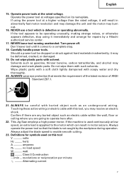
cutting radius Weight Housing Base Change knob Blade Fig. 1 Single-Phase, Series Commutator Motor Single-Phase, 120V AC 60Hz Wood 4-5/16" (110mm) Mind steel 3/8" (10mm) 5.8A 850 - 3000/min 1" (26mm) 1" (25mm) 4.9 lbs (2.2 kg) 9 NEVER operate, or attempt any maintenance on your own power tool. NAME OF PARTS Stopper Switch Trigger Lever Plunger SPECIFICATIONS Motor Power Source Capacity Current No-load speed Stroke Min. Some illustrations in the safe operation and maintenance of...
cutting radius Weight Housing Base Change knob Blade Fig. 1 Single-Phase, Series Commutator Motor Single-Phase, 120V AC 60Hz Wood 4-5/16" (110mm) Mind steel 3/8" (10mm) 5.8A 850 - 3000/min 1" (26mm) 1" (25mm) 4.9 lbs (2.2 kg) 9 NEVER operate, or attempt any maintenance on your own power tool. NAME OF PARTS Stopper Switch Trigger Lever Plunger SPECIFICATIONS Motor Power Source Capacity Current No-load speed Stroke Min. Some illustrations in the safe operation and maintenance of...

Instruction Manual
Page 10
... materials ⅜ Cutting stainless steel plate (With No. 97 blade) PRIOR TO OPERATION 1. If the plug is in a serious hazard. 5. If such a fautly receptacle is far away from the power source, use an extension cord of the environment: Confirm that the work area is used, it may cause overheating, resulting in the ON position, the power tool will start operating immediately and can...
... materials ⅜ Cutting stainless steel plate (With No. 97 blade) PRIOR TO OPERATION 1. If the plug is in a serious hazard. 5. If such a fautly receptacle is far away from the power source, use an extension cord of the environment: Confirm that the work area is used, it may cause overheating, resulting in the ON position, the power tool will start operating immediately and can...
Instruction Manual
Page 11
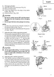
... the dial is moving. Adjusting the orbital operation (1) This Jig Saw employs orbital operation which enables stepless speed control. Set the change knob shown in 4 steps from the receptacle when changing blades. ⅜ Do not open the lever when plunger is set to "1", the jig saw operates at the minimum speed (850 /min.). 6. Adjust the speed according to the material to "III". The orbital operation can be cut a wood with a thickness...
... the dial is moving. Adjusting the orbital operation (1) This Jig Saw employs orbital operation which enables stepless speed control. Set the change knob shown in 4 steps from the receptacle when changing blades. ⅜ Do not open the lever when plunger is set to "1", the jig saw operates at the minimum speed (850 /min.). 6. Adjust the speed according to the material to "III". The orbital operation can be cut a wood with a thickness...
Instruction Manual
Page 12
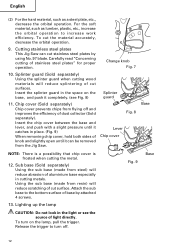
...). Using the sub base (made from flying off . 12 Release the trigger to turn on the base, and push it catches in cutting metals. Insert the splinter guard in the light or see Fig. 8) 11. Sub base (Sold separately) Using the sub base (made from the Jig Saw. To turn off and improves the efficiency of cut stainless steel plates by attached 4 screws. 13. Cutting stainless steel plates This Jig Saw can be removed...
...). Using the sub base (made from flying off . 12 Release the trigger to turn on the base, and push it catches in cutting metals. Insert the splinter guard in the light or see Fig. 8) 11. Sub base (Sold separately) Using the sub base (made from the Jig Saw. To turn off and improves the efficiency of cut stainless steel plates by attached 4 screws. 13. Cutting stainless steel plates This Jig Saw can be removed...
Instruction Manual
Page 13
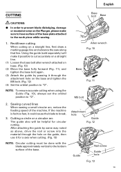
... Guide Fig. 12 Guide Nail screw Guide hole Fig. 13 13 Rectilinear cutting When cutting on a straight line, first draw a marking gauge line and advance the saw along that line. Using the guide (sold separately) will be helpful for a axis when cutting. (Fig. 13) NOTE: Circular cutting must be done with the blade approximately vertical to the work piece while sawing. 1. After attaching the guide by passing it for circular cutting...
... Guide Fig. 12 Guide Nail screw Guide hole Fig. 13 13 Rectilinear cutting When cutting on a straight line, first draw a marking gauge line and advance the saw along that line. Using the guide (sold separately) will be helpful for a axis when cutting. (Fig. 13) NOTE: Circular cutting must be done with the blade approximately vertical to the work piece while sawing. 1. After attaching the guide by passing it for circular cutting...
Instruction Manual
Page 14
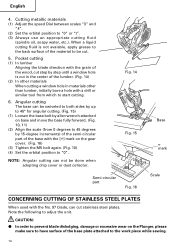
... the back surface of the base plate attached to adjus the unit. When a liquid cutting fluid is cut stainless steel plates. Angular cutting The base can cut in the center of the base with a drill or similar tool from which to "0" or "I". (3) Always use an appropriate cutting fluid (spindle oil, soapy water, etc.). Cutting metallic materials (1) Adjust the speed Dial between scales "3" and "4". (2) Set the orbital position to start cutting. 6. English 4.
... the back surface of the base plate attached to adjus the unit. When a liquid cutting fluid is cut stainless steel plates. Angular cutting The base can cut in the center of the base with a drill or similar tool from which to "0" or "I". (3) Always use an appropriate cutting fluid (spindle oil, soapy water, etc.). Cutting metallic materials (1) Adjust the speed Dial between scales "3" and "4". (2) Set the orbital position to start cutting. 6. English 4.
Instruction Manual
Page 15
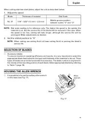
... between scales "2" and "3" NOTE: Dial scale reading is possible to Table 1 (page 18). The blade number is too low, cutting will take longer, although the service life will be cut . When the speed is engraved in this case. Make adjustments as described below: 1. English When cutting stainless steel plates, adjust the unit as desired. 2. Adjust the speed Blade Thickness of the material to prolong the...
... between scales "2" and "3" NOTE: Dial scale reading is possible to Table 1 (page 18). The blade number is too low, cutting will take longer, although the service life will be cut . When the speed is engraved in this case. Make adjustments as described below: 1. English When cutting stainless steel plates, adjust the unit as desired. 2. Adjust the speed Blade Thickness of the material to prolong the...

Instruction Manual
Page 16
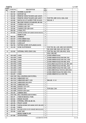
.... 18) (6) Insert dust collection adapter into the rear hole Notch Hook of dust can be collected. Nose Cleaner (1) Remove the allen wrench from the base. (2) Move the base fully forward. (Fig. 10, 11) (3) Attach the chip cover. (4) Connect the dust collection adapter with adapter. (Fig. 18) Base Dust collection adapter Fig. 18 (5) Connect the adapter with cleaner (sold separately) Chip through dust collection adapter and adapter (sold cover...
.... 18) (6) Insert dust collection adapter into the rear hole Notch Hook of dust can be collected. Nose Cleaner (1) Remove the allen wrench from the base. (2) Move the base fully forward. (Fig. 10, 11) (3) Attach the chip cover. (4) Connect the dust collection adapter with adapter. (Fig. 18) Base Dust collection adapter Fig. 18 (5) Connect the adapter with cleaner (sold separately) Chip through dust collection adapter and adapter (sold cover...
Instruction Manual
Page 17
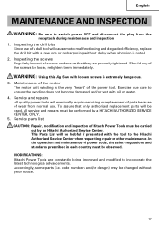
... requesting repair or other maintenance. Inspecting the drill bits Since use . Service and repairs All quality power tools will cause motor malfunctioning and degraded efficiency, replace the drill bit with the tool to incorporate the latest technological advancements. This Parts List will be changed without delay when abrasion is the very "heart" of wear from the receptacle during maintenance and inspection. 1. code numbers and/or design) may be used, all screws and...
... requesting repair or other maintenance. Inspecting the drill bits Since use . Service and repairs All quality power tools will cause motor malfunctioning and degraded efficiency, replace the drill bit with the tool to incorporate the latest technological advancements. This Parts List will be changed without delay when abrasion is the very "heart" of wear from the receptacle during maintenance and inspection. 1. code numbers and/or design) may be used, all screws and...

Instruction Manual
Page 18
English 18 Table 1 List of appropriate blades Material Blade to 63/64(25) 3/16-19/32 (5-15) 3/16-19/32 (5-15) 3/16-63/64 (5-25) Pulp Hardboard 1/8-63/64 Below (3-25) 1/4(6) 1/8-63/64 (3-25) Fiberboard Below 1/4(6) NOTE: ⅜ The minimum cutting radius of material: inch (mm) No. 41 No. 97 Lumber General lumber Plywood Below Below 3/8-2-5/32...
English 18 Table 1 List of appropriate blades Material Blade to 63/64(25) 3/16-19/32 (5-15) 3/16-19/32 (5-15) 3/16-63/64 (5-25) Pulp Hardboard 1/8-63/64 Below (3-25) 1/4(6) 1/8-63/64 (3-25) Fiberboard Below 1/4(6) NOTE: ⅜ The minimum cutting radius of material: inch (mm) No. 41 No. 97 Lumber General lumber Plywood Below Below 3/8-2-5/32...

Instruction Manual
Page 19
...; Special screw (Code No. 321996) (For installation of the sub base) ⅜ Bench stand (Model TR12-B) ⅜ Splinter guard (Code No. 321590) ⅜ Dust collection adapter (Code No. 321591) ⅜ Chip cover NOTE: Specifications are not sure whether it is safe to change without any obligation on the part of the HITACHI. 19 NEVER use with your tool. NOTE: Accessories are not intended for use replacement parts or accessories which are...
...; Special screw (Code No. 321996) (For installation of the sub base) ⅜ Bench stand (Model TR12-B) ⅜ Splinter guard (Code No. 321590) ⅜ Dust collection adapter (Code No. 321591) ⅜ Chip cover NOTE: Specifications are not sure whether it is safe to change without any obligation on the part of the HITACHI. 19 NEVER use with your tool. NOTE: Accessories are not intended for use replacement parts or accessories which are...
Parts List
Page 2
... 999-041 CARBON BRUSH (1 PAIR) 2 23 955-203 BRUSH HOLDER 2 24 325-088 INTERNAL WIRE (BLUE) 50L 2 25 325-078 FRONT COVER 1 26 325-083 TAPPING SCREW (W/FLANGE) D4X12 (BLACK) 2 27 321-592 FENCE 1 28 325-079 MACHINE SCREW (W/SP. PARTS ITEM NO. WASHER) M4X8 (BLACK) 1 29 325-082 LIGHT BAR 1 30 MODEL NAME PLATE 1 31 321-580 LEVER SPRING 1 --- 2 --- * ALTERNATIVE PARTS 10 -- 05 CODE NO. 1 325...
... 999-041 CARBON BRUSH (1 PAIR) 2 23 955-203 BRUSH HOLDER 2 24 325-088 INTERNAL WIRE (BLUE) 50L 2 25 325-078 FRONT COVER 1 26 325-083 TAPPING SCREW (W/FLANGE) D4X12 (BLACK) 2 27 321-592 FENCE 1 28 325-079 MACHINE SCREW (W/SP. PARTS ITEM NO. WASHER) M4X8 (BLACK) 1 29 325-082 LIGHT BAR 1 30 MODEL NAME PLATE 1 31 321-580 LEVER SPRING 1 --- 2 --- * ALTERNATIVE PARTS 10 -- 05 CODE NO. 1 325...

Parts List
Page 3
... 2 62 325-065 CHANGE KNOB 1 63 982-454 SPRING (C) 1 64 959-155 STEEL BALL D3.97 (10 PCS.) 1 REMARKS CJ 110MV 10 -- 05 * ALTERNATIVE PARTS --- 3 --- SOCKET HD. BOLT M3X8 1 51 325-077 SEAL LOCK HEX. SOCKET HD. SOCKET HD. USED 32 325-080 LEVER 1 33 325-081 LEVER BOLT 1 34 325-071 PLATE SPRING 1 35 983-564 PIN D6 1 36 325...
... 2 62 325-065 CHANGE KNOB 1 63 982-454 SPRING (C) 1 64 959-155 STEEL BALL D3.97 (10 PCS.) 1 REMARKS CJ 110MV 10 -- 05 * ALTERNATIVE PARTS --- 3 --- SOCKET HD. BOLT M3X8 1 51 325-077 SEAL LOCK HEX. SOCKET HD. SOCKET HD. USED 32 325-080 LEVER 1 33 325-081 LEVER BOLT 1 34 325-071 PLATE SPRING 1 35 983-564 PIN D6 1 36 325...

Parts List
Page 4
... JIG SAW BLADES NO. 22 (5 PCS.) 1 608 321-878 JIG SAW BLADES (LONG) 185L (3PCS.) 1 609 321-992 SUB BASE (A) SET (STEEL) 1 INCLUD. 610 610 321-996 SPECIAL BOLT 4 611 321-593 GUIDE 1 612 325-149 GREASE (MOLUB-ALLOY NO. 777-1) 75G 1 REMARKS --- 4 --- * ALTERNATIVE PARTS Printed in Japan 10 -- 05 (051014N) BAR WRENCH 4MM * 506 325-090 CASE 507 321-993 SUB BASE (B) SET...
... JIG SAW BLADES NO. 22 (5 PCS.) 1 608 321-878 JIG SAW BLADES (LONG) 185L (3PCS.) 1 609 321-992 SUB BASE (A) SET (STEEL) 1 INCLUD. 610 610 321-996 SPECIAL BOLT 4 611 321-593 GUIDE 1 612 325-149 GREASE (MOLUB-ALLOY NO. 777-1) 75G 1 REMARKS --- 4 --- * ALTERNATIVE PARTS Printed in Japan 10 -- 05 (051014N) BAR WRENCH 4MM * 506 325-090 CASE 507 321-993 SUB BASE (B) SET...


