Owners Guide
Page 1
... HITACHI PROJECTION TV 11 HOOK-UP CABLES AND CONNECTORS ...13 FRONT PANEL CONTROLS...15 FRONT PANEL JACKS AND CONNECTIONS...16 REAR PANEL JACKS...18 REAR SPEAKER TERMINAL CONNECTIONS...22 TIPS ON REAR PANEL CONNECTIONS ...22 EXTERNAL AUDIO SOURCES...23 CONNECTING EXTERNAL VIDEO SOURCES ...25 AUDIO SYSTEM SET-UP ...29 PICTURE-IN-PICTURE (PIP) ...36 USING THE REMOTE TO CONTROL VCR FUNCTIONS 42 USING THE REMOTE TO CONTROL CABLE BOX FUNCTIONS 44 USING THE REMOTE TO CONTROL SATELLITE RECEIVER FUNCTIONS 45 USING THE REMOTE TO CONTROL DVD FUNCTIONS 47 USING THE REMOTE TO CONTROL ADDITIONAL AUDIO...
... HITACHI PROJECTION TV 11 HOOK-UP CABLES AND CONNECTORS ...13 FRONT PANEL CONTROLS...15 FRONT PANEL JACKS AND CONNECTIONS...16 REAR PANEL JACKS...18 REAR SPEAKER TERMINAL CONNECTIONS...22 TIPS ON REAR PANEL CONNECTIONS ...22 EXTERNAL AUDIO SOURCES...23 CONNECTING EXTERNAL VIDEO SOURCES ...25 AUDIO SYSTEM SET-UP ...29 PICTURE-IN-PICTURE (PIP) ...36 USING THE REMOTE TO CONTROL VCR FUNCTIONS 42 USING THE REMOTE TO CONTROL CABLE BOX FUNCTIONS 44 USING THE REMOTE TO CONTROL SATELLITE RECEIVER FUNCTIONS 45 USING THE REMOTE TO CONTROL DVD FUNCTIONS 47 USING THE REMOTE TO CONTROL ADDITIONAL AUDIO...
Owners Guide
Page 2
... appliance. NOTE: • There are no user serviceable parts inside the television. • Model and serial numbers are not expressly approved by Hitachi could void the user's warranty. CAUTION: Adjust only those controls that may void the user's warranty. Home Electronics Division may be notified that any changes or modifications made to persons. NO USER SERVICEABLE PARTS INSIDE. The lightning flash with arrowhead symbol, within an equilateral triangle...
... appliance. NOTE: • There are no user serviceable parts inside the television. • Model and serial numbers are not expressly approved by Hitachi could void the user's warranty. CAUTION: Adjust only those controls that may void the user's warranty. Home Electronics Division may be notified that any changes or modifications made to persons. NO USER SERVICEABLE PARTS INSIDE. The lightning flash with arrowhead symbol, within an equilateral triangle...
Owners Guide
Page 6
... ventilation purposes which provide reliable operation of the NEC that 6 Accumulated dust inside the chassis may cause failure of the television when high humidity persists. 15 The television has slots, or openings in wire to an antenna discharge unit, size of grounding conductors, location of antenna discharge unit connection to grounding electrode, and requirements for television with respect to provide some...
... ventilation purposes which provide reliable operation of the NEC that 6 Accumulated dust inside the chassis may cause failure of the television when high humidity persists. 15 The television has slots, or openings in wire to an antenna discharge unit, size of grounding conductors, location of antenna discharge unit connection to grounding electrode, and requirements for television with respect to provide some...
Owners Guide
Page 7
... adjustment. When installing an outside antenna system, extreme care should be taken to keep from touching such power lines or circuits as practical. 17 An outside antenna system should be operated only from the wall outlet and disconnect antenna. For televisions designed to operate from the wall outlet and refer servicing to qualified service personnel. This will often require extensive work by following the operating instructions...
... adjustment. When installing an outside antenna system, extreme care should be taken to keep from touching such power lines or circuits as practical. 17 An outside antenna system should be operated only from the wall outlet and disconnect antenna. For televisions designed to operate from the wall outlet and refer servicing to qualified service personnel. This will often require extensive work by following the operating instructions...
Owners Guide
Page 11
... exceptionally good signal area that the location selected allows a free flow of air to the left and right of the cover with your TV is connected to a cable TV system or to a centralized antenna system, a good outdoor color TV antenna is recommended for the best performance. Picture brightness decreases as the viewer moves to and from the perforated back cover of the HITACHI Projection Television is free from the screen. Also...
... exceptionally good signal area that the location selected allows a free flow of air to the left and right of the cover with your TV is connected to a cable TV system or to a centralized antenna system, a good outdoor color TV antenna is recommended for the best performance. Picture brightness decreases as the viewer moves to and from the perforated back cover of the HITACHI Projection Television is free from the screen. Also...
Owners Guide
Page 16
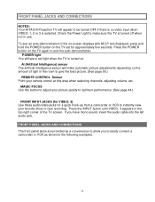
... the TV screen. FRONT PANEL JACKS AND CONNECTIONS The front panel jacks are provided as a convenience to allow you have mono sound, insert the audio cable into the left audio jack. MAGIC FOCUS Use this area when selecting channels, adjusting volume, etc. Press the POWER button on the TV again to optimum performance. (See page 44.) FRONT INPUT JACKS (for VIDEO: 3) Use these audio/video jacks for approximately five seconds. To see a red light...
... the TV screen. FRONT PANEL JACKS AND CONNECTIONS The front panel jacks are provided as a convenience to allow you have mono sound, insert the audio cable into the left audio jack. MAGIC FOCUS Use this area when selecting channels, adjusting volume, etc. Press the POWER button on the TV again to optimum performance. (See page 44.) FRONT INPUT JACKS (for VIDEO: 3) Use these audio/video jacks for approximately five seconds. To see a red light...

Owners Guide
Page 20
... may be viewed as a blank PIP sub-picture. (see page 26) (9) SUB WOOFER This jack provides variable audio output to the TV's CR input. REAR PANEL JACKS NOTES: DO NOT connect standard VIDEO or S-VIDEO to the TV's INPUT 2 Left and Right Audio input jacks. When using the Y-CB-CR input jacks, connect your components audio output to INPUT 2 when using the Y-CB-CR jacks, INPUT 2 will be controlled by the television's main volume and also by...
... may be viewed as a blank PIP sub-picture. (see page 26) (9) SUB WOOFER This jack provides variable audio output to the TV's CR input. REAR PANEL JACKS NOTES: DO NOT connect standard VIDEO or S-VIDEO to the TV's INPUT 2 Left and Right Audio input jacks. When using the Y-CB-CR input jacks, connect your components audio output to INPUT 2 when using the Y-CB-CR jacks, INPUT 2 will be controlled by the television's main volume and also by...
Owners Guide
Page 22
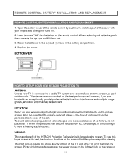
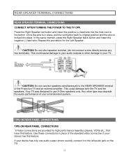
REAR SPEAKER TERMINAL CONNECTIONS REAR SPEAKER TERMINAL CONNECTIONS CONNECT AFTER TURNING THE POWER TO THE TV OFF. Press the Right Speaker red button and insert the positive (+) lead wire into place. CAUTION: Do not short speaker terminal, (do not connect a wire directly across any two terminals). TIPS ON REAR PANEL CONNECTIONS TIPS ON REAR PANEL CONNECTIONS S-Video connections are provided for the Left Speaker. Once the wire is locked into the hole next to your audio outputs or...
REAR SPEAKER TERMINAL CONNECTIONS REAR SPEAKER TERMINAL CONNECTIONS CONNECT AFTER TURNING THE POWER TO THE TV OFF. Press the Right Speaker red button and insert the positive (+) lead wire into place. CAUTION: Do not short speaker terminal, (do not connect a wire directly across any two terminals). TIPS ON REAR PANEL CONNECTIONS TIPS ON REAR PANEL CONNECTIONS S-Video connections are provided for the Left Speaker. Once the wire is locked into the hole next to your audio outputs or...

Owners Guide
Page 23
... own video or line output. (INPUT 1 in place of your other electronic equipment for high performance components, such as a blank PIP sub-picture. (see page 26) EXTERNAL AUDIO SOURCES CONNECTING EXTERNAL AUDIO AMPLIFIER 23 When using Y-CB-CR jacks. COMPONENT VIDEO: Y-CB-CR connections are provided for additional information on line input-output connection. EXTERNAL AUDIO SOURCES Refer to the operating guide of the standard video connection if your components audio output to the TV's INPUT 2 Left and Right Audio input...
... own video or line output. (INPUT 1 in place of your other electronic equipment for high performance components, such as a blank PIP sub-picture. (see page 26) EXTERNAL AUDIO SOURCES CONNECTING EXTERNAL AUDIO AMPLIFIER 23 When using Y-CB-CR jacks. COMPONENT VIDEO: Y-CB-CR connections are provided for additional information on line input-output connection. EXTERNAL AUDIO SOURCES Refer to the operating guide of the standard video connection if your components audio output to the TV's INPUT 2 Left and Right Audio input...
Owners Guide
Page 25
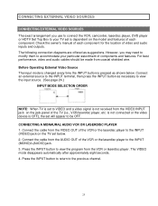
... video and audio inputs and outputs. Check the owner's manual of each component. CONNECTING A MONAURAL AUDIO VCR OR LASERDISC PLAYER 1. However, you use to connect the VCR, camcorder, laserdisc player, DVD player or HDTV Set Top Box to your particular assortment of the VCR or the laserdisc player to the INPUT terminal, then press the INPUT button as suggestions. Connect an external source to the INPUT (MONO)/L(AUDIO) jack. 3. Press the INPUT button to the previous channel. 25 Connect the cable...
... video and audio inputs and outputs. Check the owner's manual of each component. CONNECTING A MONAURAL AUDIO VCR OR LASERDISC PLAYER 1. However, you use to connect the VCR, camcorder, laserdisc player, DVD player or HDTV Set Top Box to your particular assortment of the VCR or the laserdisc player to the INPUT terminal, then press the INPUT button as suggestions. Connect an external source to the INPUT (MONO)/L(AUDIO) jack. 3. Press the INPUT button to the previous channel. 25 Connect the cable...

Owners Guide
Page 27
... line input-output connections. CONNECTING EXTERNAL VIDEO SOURCES CONNECTING A STEREO VCR OR STEREO LASERDISC PLAYER 1. NOTES: Completely insert the connection cord plugs when connecting to view the program from the AUDIO OUT R of the VCR or the laserdisc player to the INPUT 2 (CB) jack, as shown on the TV set below. 27 A single VCR can be used for more information on the TV set below . 2. Connect the cable from the VCR or laserdisc player. The mode VIDEO...
... line input-output connections. CONNECTING EXTERNAL VIDEO SOURCES CONNECTING A STEREO VCR OR STEREO LASERDISC PLAYER 1. NOTES: Completely insert the connection cord plugs when connecting to view the program from the AUDIO OUT R of the VCR or the laserdisc player to the INPUT 2 (CB) jack, as shown on the TV set below. 27 A single VCR can be used for more information on the TV set below . 2. Connect the cable from the VCR or laserdisc player. The mode VIDEO...
Owners Guide
Page 29
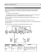
... OPTIONAL FEATURE CONNECTION CONNECTION EFFECT OFF (1) (3) (5) (6) Receive mono and stereo sound. HALL (1) (4) (3) (5) (6) Gives the listener concert hall sound. 29 Use the WIRELESS OUT output on the TV. (6) This sub woofer is in SURROUND-PRO LOGIC, or SURROUND-DOLBY 3 STEREO mode. (3) These speakers are controlled by a wireless speaker transmitter. AUDIO SYSTEM SET-UP AUDIO SYSTEM SET-UP Match the numbers below to the diagrams for SURROUND functions.) The television's internal speakers.
... OPTIONAL FEATURE CONNECTION CONNECTION EFFECT OFF (1) (3) (5) (6) Receive mono and stereo sound. HALL (1) (4) (3) (5) (6) Gives the listener concert hall sound. 29 Use the WIRELESS OUT output on the TV. (6) This sub woofer is in SURROUND-PRO LOGIC, or SURROUND-DOLBY 3 STEREO mode. (3) These speakers are controlled by a wireless speaker transmitter. AUDIO SYSTEM SET-UP AUDIO SYSTEM SET-UP Match the numbers below to the diagrams for SURROUND functions.) The television's internal speakers.
Owners Guide
Page 31
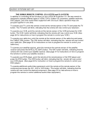
... cable box and press the CABLE (CBL) button. The DVD button will blink, indicating that the remote will now control your DVD player. (See page 32 for instructions on how to program the remote to control your DVD player.) To operate additional audio/video equipment, point the remote at the remote sensor of the component and press the AV1, AV2 or AV3 button. AUDIO SYSTEM SET-UP THE GENIUS REMOTE CONTROL (CLU-573TSI and CLU-574TSI) In addition to controlling...
... cable box and press the CABLE (CBL) button. The DVD button will blink, indicating that the remote will now control your DVD player. (See page 32 for instructions on how to program the remote to control your DVD player.) To operate additional audio/video equipment, point the remote at the remote sensor of the component and press the AV1, AV2 or AV3 button. AUDIO SYSTEM SET-UP THE GENIUS REMOTE CONTROL (CLU-573TSI and CLU-574TSI) In addition to controlling...

Owners Guide
Page 34
... timer is set, it will reset to the original condition. (11) LAST CHANNEL (LAST CH) button Use this button to view HELP text, which gives a description of the displayed menu. If the Picture-in-Picture is on, the INPUT button will select between the three sets of video input jacks each time the button is pressed. If the sub-picture is chosen, the INPUT button will select between antenna signal and the three sets of video input...
... timer is set, it will reset to the original condition. (11) LAST CHANNEL (LAST CH) button Use this button to view HELP text, which gives a description of the displayed menu. If the Picture-in-Picture is on, the INPUT button will select between the three sets of video input jacks each time the button is pressed. If the sub-picture is chosen, the INPUT button will select between antenna signal and the three sets of video input...

Owners Guide
Page 45
... remote to switch to instruction manual of the Cable Box for the Cable Box. The remote will remember the codes you have programmed until the batteries are for your satellite receiver. (refer to CABLE mode. (2) PRECODED CABLE Box buttons These buttons transmit the chosen precoded cable codes. (3) EXCLUSIVE TV buttons These buttons are removed from the remote control. The LAST CH button will act as shown on the remote and enter the two digit preset code that your cable box cannot be operated...
... remote to switch to instruction manual of the Cable Box for the Cable Box. The remote will remember the codes you have programmed until the batteries are for your satellite receiver. (refer to CABLE mode. (2) PRECODED CABLE Box buttons These buttons transmit the chosen precoded cable codes. (3) EXCLUSIVE TV buttons These buttons are removed from the remote control. The LAST CH button will act as shown on the remote and enter the two digit preset code that your cable box cannot be operated...
Owners Guide
Page 57
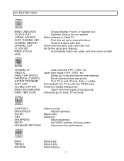
... picture and sound. Feature to factory preset. Set VIDEO settings to display dialogue/text. Channel buttons, add, skip. Automatically turn TV on and off once, daily, or weekly. Adjust color. BASS TREBLE BALANCE Adjust bass. Automatically match red, green, and blue colors to basic TV functions. CONTRAST BRIGHTNESS COLOR TINT SHARPNESS RESET ADVANCED SETTINGS Adjust contrast. Check channel name, scan, and child lock. Select Antenna or Cable TV. Allows you to make CHANNEL ID VIDEO ID FAMILY FAVORITES PARENTAL CONTROL 4 EVENT PROGRAM AUTO LINK CLOSED CAPTION MENU...
... picture and sound. Feature to factory preset. Set VIDEO settings to display dialogue/text. Channel buttons, add, skip. Automatically turn TV on and off once, daily, or weekly. Adjust color. BASS TREBLE BALANCE Adjust bass. Automatically match red, green, and blue colors to basic TV functions. CONTRAST BRIGHTNESS COLOR TINT SHARPNESS RESET ADVANCED SETTINGS Adjust contrast. Check channel name, scan, and child lock. Select Antenna or Cable TV. Allows you to make CHANNEL ID VIDEO ID FAMILY FAVORITES PARENTAL CONTROL 4 EVENT PROGRAM AUTO LINK CLOSED CAPTION MENU...
Owners Guide
Page 60
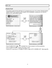
Press THUMB STICK or to highlight the correct answers to display the graphic guide. Press THUMB STICK to all three questions. Press EXIT to quit menu or THUMB STICK to begin AUTO CHANNEL SET. (See page 40). 60 Simply answer three questions and a graphic will help you the optimum setup for your TV or Home Theater System. SET UP PLUG & PLAY This graphic guide function will be displayed, showing you to properly set up your personalized system.
Press THUMB STICK or to highlight the correct answers to display the graphic guide. Press THUMB STICK to all three questions. Press EXIT to quit menu or THUMB STICK to begin AUTO CHANNEL SET. (See page 40). 60 Simply answer three questions and a graphic will help you the optimum setup for your TV or Home Theater System. SET UP PLUG & PLAY This graphic guide function will be displayed, showing you to properly set up your personalized system.

Owners Guide
Page 62
If the EXIT button is pressed while the AUTO CHANNEL SET function is engaged, programming will automatically store active TV channels in CHANNEL MEMORY. Remember to skip unused channels when using AUTO CHANNEL SET. See CHANNEL MEMORY to add or to the remote control CHANNEL or buttons. 62 CHANNEL MEMORY Use this function after AUTO CHANNEL SET to add or erase additional channels to erase additional channels. SET UP AUTO CHANNEL SET This feature will stop. This will allow you to select the correct SIGNAL SOURCE mode before using the CHANNEL UP ( ) or DOWN ( ).
If the EXIT button is pressed while the AUTO CHANNEL SET function is engaged, programming will automatically store active TV channels in CHANNEL MEMORY. Remember to skip unused channels when using AUTO CHANNEL SET. See CHANNEL MEMORY to add or to the remote control CHANNEL or buttons. 62 CHANNEL MEMORY Use this function after AUTO CHANNEL SET to add or erase additional channels to erase additional channels. SET UP AUTO CHANNEL SET This feature will stop. This will allow you to select the correct SIGNAL SOURCE mode before using the CHANNEL UP ( ) or DOWN ( ).
Owners Guide
Page 66
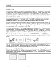
... SETUP Menu. Properly converged, the lines appear white, which the TV to self-adjust. The outputs of alignment due to normal bumps and vibrations or moving the TV. When mixed together in the picture, you may want to converge (align) the colors. If one for blue. SET UP MAGIC FOCUS Your HITACHI Projection TV has three color projection tubes: one for red, one for green, one of the pictures shown below appears on the television screen...
... SETUP Menu. Properly converged, the lines appear white, which the TV to self-adjust. The outputs of alignment due to normal bumps and vibrations or moving the TV. When mixed together in the picture, you may want to converge (align) the colors. If one for blue. SET UP MAGIC FOCUS Your HITACHI Projection TV has three color projection tubes: one for red, one for green, one of the pictures shown below appears on the television screen...
Owners Guide
Page 82
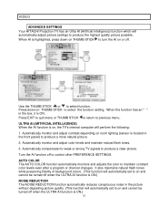
... AUTO COLOR function automatically monitors and adjusts the color to produce a clear picture. Automatically compensate for weak or strong TV signals to maintain constant color levels even after a program or channel changes. Use the THUMB STICK or to produce a more natural picture. 2. Automatically monitor and adjust color levels and maintain natural flesh tones. 3. Automatically monitor and adjust contrast depending on room lighting (sensor is on, the TV's internal computer will automatically set...
... AUTO COLOR function automatically monitors and adjusts the color to produce a clear picture. Automatically compensate for weak or strong TV signals to maintain constant color levels even after a program or channel changes. Use the THUMB STICK or to produce a more natural picture. 2. Automatically monitor and adjust color levels and maintain natural flesh tones. 3. Automatically monitor and adjust contrast depending on room lighting (sensor is on, the TV's internal computer will automatically set...


