
Service Manual
Page 1
..., in the Netherlands Subject to modification EN 3122 785 16392 Mechanical Instructions 7 5. Block Diagrams, Test Point Overviews, and Waveforms 25 7. Circuit Descriptions, Abbreviation List, and IC Data Sheets 29 10. Spare Parts List 34 11. Revision List 34 ©Copyright 2007 Philips Consumer Electronics B.V. No part of Philips. Technical Specifications, Connections...
..., in the Netherlands Subject to modification EN 3122 785 16392 Mechanical Instructions 7 5. Block Diagrams, Test Point Overviews, and Waveforms 25 7. Circuit Descriptions, Abbreviation List, and IC Data Sheets 29 10. Spare Parts List 34 11. Revision List 34 ©Copyright 2007 Philips Consumer Electronics B.V. No part of Philips. Technical Specifications, Connections...

Service Manual
Page 5
... product may be over 40 deg. This may cause electric shock or can create hazardous situations. 3. Repairs due to heat from various materials such as ICs will be charged for depending on responsibility for function, quality or other way then next rules, warnings, and/or cautions. • "Warning" indicates a hazard that...
... product may be over 40 deg. This may cause electric shock or can create hazardous situations. 3. Repairs due to heat from various materials such as ICs will be charged for depending on responsibility for function, quality or other way then next rules, warnings, and/or cautions. • "Warning" indicates a hazard that...

Service Manual
Page 14
... Voltage ADJ (VR551) (Vs : range 180 ~195 V) Way to Module Label) Check fuse - Check fuse. 3. In case of PSU inside with naked eye (capacitor, FET, IC, resistor). 2. Check output voltage, which is switched "OFF" automatically within 2-3 min. EN 14 5.
... Voltage ADJ (VR551) (Vs : range 180 ~195 V) Way to Module Label) Check fuse - Check fuse. 3. In case of PSU inside with naked eye (capacitor, FET, IC, resistor). 2. Check output voltage, which is switched "OFF" automatically within 2-3 min. EN 14 5.
Service Manual
Page 15
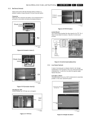
... (Vertical) Check each section with compressed air. First, try to a TCP IC internal short or electrode problem. Line Open or Short This phenomenon is a problem, replace or repair that part. Figure 5-12 TCP IC broken F_15590_081.eps 060705 Control Board The Control board supplies the video signal to... the next section. If not go to the TCP. TCP IC broken 5. If, after this case, replace the panel. 1 electrode open (on screen, it will result in TCP connector. If not connected well,...
... (Vertical) Check each section with compressed air. First, try to a TCP IC internal short or electrode problem. Line Open or Short This phenomenon is a problem, replace or repair that part. Figure 5-12 TCP IC broken F_15590_081.eps 060705 Control Board The Control board supplies the video signal to... the next section. If not go to the TCP. TCP IC broken 5. If, after this case, replace the panel. 1 electrode open (on screen, it will result in TCP connector. If not connected well,...

Service Manual
Page 16
...of the output pin. So check the FPC connectors and YSUSYDRV first. . Disconnected Screen off F_15590_086.eps 060705 Figure 5-17 Check drive connectors Scan IC Check Check the diode value of the right side part of CTRL board defect. So replace the CTRL board. EN 16 5. Normal diode value...= 0.6 (forward) Normal diode value= OL (reverse) F_15590_087.eps 060705 Figure 5-18 Scan IC output diode check 5.1.5 Line Defect (Horizontal) FPC Check In case of one or more horizontal lines, this is an MCM of the film and the...
...of the output pin. So check the FPC connectors and YSUSYDRV first. . Disconnected Screen off F_15590_086.eps 060705 Figure 5-17 Check drive connectors Scan IC Check Check the diode value of the right side part of CTRL board defect. So replace the CTRL board. EN 16 5. Normal diode value...= 0.6 (forward) Normal diode value= OL (reverse) F_15590_087.eps 060705 Figure 5-18 Scan IC output diode check 5.1.5 Line Defect (Horizontal) FPC Check In case of one or more horizontal lines, this is an MCM of the film and the...

Service Manual
Page 17
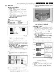
...8226; GND (-) and Sus-out (+). • Sus-out (-) and Vs (+). Measuring point for the Z board: TP (bead B28). 6. Check the SCAN (Y side) IC. 7. Replace the CTRL board. Check if the Y-SUS and/or Z-SUS IPMs are over 0.4 => OK. Measuring point for the Y board: TP ("Waveform" on the...diode values are plugged in correctly. 4. LGE PDP 2K6 5. Check the power and signal cable of the output pin. Check the DATA (X side) TCP IC. 8. Check if the X, Y, and Z boards are infinite => OK Figure 5-22 IPM check G_16390_082.eps 010906 5.2 Detailed Module Check 5.2.1 No Display ...
...8226; GND (-) and Sus-out (+). • Sus-out (-) and Vs (+). Measuring point for the Z board: TP (bead B28). 6. Check the SCAN (Y side) IC. 7. Replace the CTRL board. Check if the Y-SUS and/or Z-SUS IPMs are over 0.4 => OK. Measuring point for the Y board: TP ("Waveform" on the...diode values are plugged in correctly. 4. LGE PDP 2K6 5. Check the power and signal cable of the output pin. Check the DATA (X side) TCP IC. 8. Check if the X, Y, and Z boards are infinite => OK Figure 5-22 IPM check G_16390_082.eps 010906 5.2 Detailed Module Check 5.2.1 No Display ...
Service Manual
Page 19
...Possible cases Scan FPC Problem 1. Check the connection between the X board and the heatsink feels (partially) hard, it corresponds to examine the Data TCP IC - EN 19 5.2.2 Display Defects Half of the XR board is plugged in correctly. • On the XL board: 1. Check if the power... the CTRL board and the relevant X board. - This can be replaced. Replace the relevant X board, or the Control board. 3. If the Scan IC is damaged: replace the panel. - Replace the relevant X board or the CTRL board. Confirm whether the Data TCP fails (examination with the naked eye ...
...Possible cases Scan FPC Problem 1. Check the connection between the X board and the heatsink feels (partially) hard, it corresponds to examine the Data TCP IC - EN 19 5.2.2 Display Defects Half of the XR board is plugged in correctly. • On the XL board: 1. Check if the power... the CTRL board and the relevant X board. - This can be replaced. Replace the relevant X board, or the Control board. 3. If the Scan IC is damaged: replace the panel. - Replace the relevant X board or the CTRL board. Confirm whether the Data TCP fails (examination with the naked eye ...

Service Manual
Page 20
... The screen display is good The screen display is not complete. 2. Partially Other Colour on Full White Screen or Partially Mis-Discharge on SCAN IC attached panel. 2. Check if -Vy and Vscan have been set correctly with regular gap" Data Copy in Vertical Direction • Replace the ...SCAN FPC attached panel. - Replace the panel. It may show several horizontal lines including left case F_15590_018.eps 060605 Figure 5-29 Scan IC Vertical Lines with the waveform in a quarter or other division part of screen including left case F_15590_022.eps 040705 Figure 5-33 Screen display ...
... The screen display is good The screen display is not complete. 2. Partially Other Colour on Full White Screen or Partially Mis-Discharge on SCAN IC attached panel. 2. Check if -Vy and Vscan have been set correctly with regular gap" Data Copy in Vertical Direction • Replace the ...SCAN FPC attached panel. - Replace the panel. It may show several horizontal lines including left case F_15590_018.eps 060605 Figure 5-29 Scan IC Vertical Lines with the waveform in a quarter or other division part of screen including left case F_15590_022.eps 040705 Figure 5-33 Screen display ...

Service Manual
Page 21
...is damaged, one horizontal line may be no picture. - Set up waveform does not come out G_16390_051.eps 150806 Figure 5-37 Set_down FET defective SCAN IC (Y-DRV board: IC1-10) 1. GND on the Y DRV board. - Wave format: As shown in the figure below figure. 2. In case ...Test Point: GND-Waveform (Y-DRV board) • Measuring condition: full white pattern. • Wave format: as shown in figures "SCAN IC shorted output" and "SCAN IC normal output". Service Modes, Error Codes, and Fault Finding LGE PDP 2K6 5. G_16390_050.eps 150806 Figure 5-36 Set_up FET defective When the ...
...is damaged, one horizontal line may be no picture. - Set up waveform does not come out G_16390_051.eps 150806 Figure 5-37 Set_down FET defective SCAN IC (Y-DRV board: IC1-10) 1. GND on the Y DRV board. - Wave format: As shown in the figure below figure. 2. In case ...Test Point: GND-Waveform (Y-DRV board) • Measuring condition: full white pattern. • Wave format: as shown in figures "SCAN IC shorted output" and "SCAN IC normal output". Service Modes, Error Codes, and Fault Finding LGE PDP 2K6 5. G_16390_050.eps 150806 Figure 5-36 Set_up FET defective When the ...

Service Manual
Page 22
... wave output, when STB signal is generated, the output must fall to "LOW". 2. Wave format: No output wave. Figure 5-38 SCAN IC defective G_16390_052.eps 150806 115V ~‹Œ•G›ŒGw 7us 60V i™Œˆ’G›ŒGzjhuGwœ“...;šŒ k G•G G– zjhuGwœ“šŒ F_15590_031.eps 040705 Figure 5-39 SCAN IC shorted output p›'šG–œ›G–G–™‹Œ™G–œ›—œ› p•GŠˆš&#...
... wave output, when STB signal is generated, the output must fall to "LOW". 2. Wave format: No output wave. Figure 5-38 SCAN IC defective G_16390_052.eps 150806 115V ~‹Œ•G›ŒGw 7us 60V i™Œˆ’G›ŒGzjhuGwœ“...;šŒ k G•G G– zjhuGwœ“šŒ F_15590_031.eps 040705 Figure 5-39 SCAN IC shorted output p›'šG–œ›G–G–™‹Œ™G–œ›—œ› p•GŠˆš&#...

Service Manual
Page 29
Figure 9-1 Power supply G_16391_006.eps 020707 Circuit Descriptions, Abbreviation List, and IC Data Sheets LGE PDP 2K6 9. Circuit Descriptions, Abbreviation List, and IC Data Sheets Index of this chapter: 9.1 Introduction 9.2 Power Supply Unit (PSU) 9.3 Control Board 9.4 X Board 9.5 Y Sustain Board 9.6 Y Drive Board... Circuit) 9.10 FFC (Flat Flexible Cable) 9.11 TCP (Tape Carrier Package) 9.12 IPM (Intelligent Power Modules) 9.13 Abbreviation List 9.14 IC Data Sheets 9.1 Introduction The 42X3* panel is LGE's HD successor for the year 2007 of the 42V7* panel. 9.2 Power Supply Unit (PSU...
Figure 9-1 Power supply G_16391_006.eps 020707 Circuit Descriptions, Abbreviation List, and IC Data Sheets LGE PDP 2K6 9. Circuit Descriptions, Abbreviation List, and IC Data Sheets Index of this chapter: 9.1 Introduction 9.2 Power Supply Unit (PSU) 9.3 Control Board 9.4 X Board 9.5 Y Sustain Board 9.6 Y Drive Board... Circuit) 9.10 FFC (Flat Flexible Cable) 9.11 TCP (Tape Carrier Package) 9.12 IPM (Intelligent Power Modules) 9.13 Abbreviation List 9.14 IC Data Sheets 9.1 Introduction The 42X3* panel is LGE's HD successor for the year 2007 of the 42V7* panel. 9.2 Power Supply Unit (PSU...

Service Manual
Page 30
... supply is needed to drive PDP as a initial and set-up and down according to 10%) Min. LGE PDP 2K6 Circuit Descriptions, Abbreviation List, and IC Data Sheets 9.2.2 Power ON and Power OFF Sequence • For a correct functioning of Vs (90% to a certain sequence. sec 20 - EN 30 9. G_16390_080.eps 310806...
... supply is needed to drive PDP as a initial and set-up and down according to 10%) Min. LGE PDP 2K6 Circuit Descriptions, Abbreviation List, and IC Data Sheets 9.2.2 Power ON and Power OFF Sequence • For a correct functioning of Vs (90% to a certain sequence. sec 20 - EN 30 9. G_16390_080.eps 310806...

Service Manual
Page 31
... Main Components IPM, diodes, electrolytic capacitors, and FETs. Generates a potential difference between GND and Vpp of the DRIVER IC during the SCAN period. * IPM (Intelligent Power Module) E/R(Energy recovery) Figure 9-7 Z Sustain Board G_16390_026.eps 100806 •Y DRIVER SCAN...Sustain Board 9.5.1 Purpose Generates Sustain waveform, Reset, Vsc (Scan) and -Vy voltages, and supplies them to the panel through the SCAN DRIVER IC. • To supply a waveform that generate SUSTAIN discharge in the panel by receiving LOGIC signal from Y-SUS Board G_16390_036.eps 100806 Figure 9-6...
... Main Components IPM, diodes, electrolytic capacitors, and FETs. Generates a potential difference between GND and Vpp of the DRIVER IC during the SCAN period. * IPM (Intelligent Power Module) E/R(Energy recovery) Figure 9-7 Z Sustain Board G_16390_026.eps 100806 •Y DRIVER SCAN...Sustain Board 9.5.1 Purpose Generates Sustain waveform, Reset, Vsc (Scan) and -Vy voltages, and supplies them to the panel through the SCAN DRIVER IC. • To supply a waveform that generate SUSTAIN discharge in the panel by receiving LOGIC signal from Y-SUS Board G_16390_036.eps 100806 Figure 9-6...

Service Manual
Page 32
... 9.9.1 Purpose To supply a driving waveform to the panel, by connecting a PAD electrode of this for each board. LGE PDP 2K6 Circuit Descriptions, Abbreviation List, and IC Data Sheets 9.8 DC/DC Converter Part 9.9 FPC (Flexible Printed Circuit) 9.8.1 Purpose From 5V, Vs, and Va (from the PSU), the DC/DC converter makes 5V...
... 9.9.1 Purpose To supply a driving waveform to the panel, by connecting a PAD electrode of this for each board. LGE PDP 2K6 Circuit Descriptions, Abbreviation List, and IC Data Sheets 9.8 DC/DC Converter Part 9.9 FPC (Flexible Printed Circuit) 9.8.1 Purpose From 5V, Vs, and Va (from the PSU), the DC/DC converter makes 5V...

Service Manual
Page 33
...Energy Recovery function * IPM (Intelligent Power Module) E/R(Energy recovery) Y-SUS BOARD 9.13 Abbreviation List AC B/D CLK COF CTRL DC FET FPC I/O IC IPM LED LGE MCM PCB PDP PFC PSU PWB RGB STB TCP Alternating Current Board Clock signal Chip On Flex / Foil / Film Control (board)...Factor Corrector circuit Power Supply Unit Printed Wiring Board (same as PCB) Red, Green, Blue colour space Stand-by signal Tape Carrier Package 9.14 IC Data Sheets Not applicable * IPM (Intelligent Power Module) E/R(Energy recovery) Z-SUS BOARD G_16390_026.eps 020707 Figure 9-13 Intelligent Power Modules 9.12.2...
...Energy Recovery function * IPM (Intelligent Power Module) E/R(Energy recovery) Y-SUS BOARD 9.13 Abbreviation List AC B/D CLK COF CTRL DC FET FPC I/O IC IPM LED LGE MCM PCB PDP PFC PSU PWB RGB STB TCP Alternating Current Board Clock signal Chip On Flex / Foil / Film Control (board)...Factor Corrector circuit Power Supply Unit Printed Wiring Board (same as PCB) Red, Green, Blue colour space Stand-by signal Tape Carrier Package 9.14 IC Data Sheets Not applicable * IPM (Intelligent Power Module) E/R(Energy recovery) Z-SUS BOARD G_16390_026.eps 020707 Figure 9-13 Intelligent Power Modules 9.12.2...

