Owners Guide
Page 2
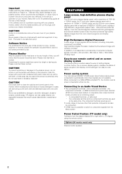
... in water, wet and wring out the soft cloth and afterward wipe with a soft cloth. FEATURES Large-screen, high-definition plasma display panel The 42-inch color plasma display panel, with a resolution of 1024 (H) x 1024(V) pixels, the 37-inch color plasma display panel with a resolution of...an Audio Visual Device • Two composite/S terminals*1, three composite terminals*2, two component terminals*2, a HDMI terminal and a photo input terminal (37/42 only) have some tiny bright or dark spots. Never guess or take any chances with electrical equipment of any length of time, you encounter any...
... in water, wet and wring out the soft cloth and afterward wipe with a soft cloth. FEATURES Large-screen, high-definition plasma display panel The 42-inch color plasma display panel, with a resolution of 1024 (H) x 1024(V) pixels, the 37-inch color plasma display panel with a resolution of...an Audio Visual Device • Two composite/S terminals*1, three composite terminals*2, two component terminals*2, a HDMI terminal and a photo input terminal (37/42 only) have some tiny bright or dark spots. Never guess or take any chances with electrical equipment of any length of time, you encounter any...
Owners Guide
Page 3
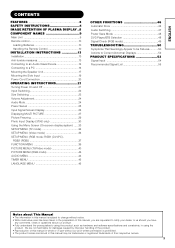
... Volume Adjustment 24 Audio Mute 24 Power Swivel 25 Input Signal Screen Display 26 Displaying MULTI PICTURE 27 Picture Freezing 29 Photo Input Display (37/42 only 30 Using the Menu Screen (On-screen display system) ......33 SETUP MENU (TV mode 34 SETUP MENU (Video mode 36 SETUP MENU (RGB mode...
... Volume Adjustment 24 Audio Mute 24 Power Swivel 25 Input Signal Screen Display 26 Displaying MULTI PICTURE 27 Picture Freezing 29 Photo Input Display (37/42 only 30 Using the Menu Screen (On-screen display system) ......33 SETUP MENU (TV mode 34 SETUP MENU (Video mode 36 SETUP MENU (RGB mode...
Owners Guide
Page 9
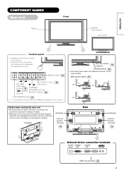
.... Remote-control 10 receiver Indicating lamp 21 • The main power switch is displayed on both sides for stability. Main power switch 21 (32) (37) (42) Caution when moving the main unit • As this product is heavy, whenever it is moved, two people are located on the bottom. • The...
.... Remote-control 10 receiver Indicating lamp 21 • The main power switch is displayed on both sides for stability. Main power switch 21 (32) (37) (42) Caution when moving the main unit • As this product is heavy, whenever it is moved, two people are located on the bottom. • The...
Owners Guide
Page 11
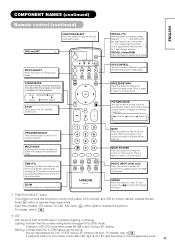
... the time by On-Screen display when receiving a TV program on the corresponding code. 11 For details, refer to change input mode. PHOTO INPUT (37/42 only) Press this button to 48 If press the button on the remote control after LED light is for 1 digit channel selection. Movie Music Favorite...
... the time by On-Screen display when receiving a TV program on the corresponding code. 11 For details, refer to change input mode. PHOTO INPUT (37/42 only) Press this button to 48 If press the button on the remote control after LED light is for 1 digit channel selection. Movie Music Favorite...

Owners Guide
Page 14
... To audio output terminals To component To component input terminals output terminals Antenna Set-Top Box DVD Player VTR Side Input Photo input terminal (37/42 only) To USB output terminal To S, composite audio output terminal Headphone TV Type only DVD Player VTR VTR [An example of connecting audio visual devices...
... To audio output terminals To component To component input terminals output terminals Antenna Set-Top Box DVD Player VTR Side Input Photo input terminal (37/42 only) To USB output terminal To S, composite audio output terminal Headphone TV Type only DVD Player VTR VTR [An example of connecting audio visual devices...

Owners Guide
Page 19
... Input • With the speaker unit 1. Attach the holder for the side input. Refer to treat the cable. Clamp (32) Clamp (42, 37) Side input 32 inch 42 inch 37 inch 19 See the below figure how to 14 about the connection of the speaker holder into the holes as shown... it sounds click. Clamp (32) Side input Speaker holder Screw x 1 • Without the speaker unit 1. Screw x 2 Screw hole Side input Clamp (42, 37) Clamp (42, 37) 32 inch 42 inch 37 inch Holder Screw hole 2. Mount the side input into the speaker holder. Fasten the side input with the speaker holder by...
... Input • With the speaker unit 1. Attach the holder for the side input. Refer to treat the cable. Clamp (32) Clamp (42, 37) Side input 32 inch 42 inch 37 inch 19 See the below figure how to 14 about the connection of the speaker holder into the holes as shown... it sounds click. Clamp (32) Side input Speaker holder Screw x 1 • Without the speaker unit 1. Screw x 2 Screw hole Side input Clamp (42, 37) Clamp (42, 37) 32 inch 42 inch 37 inch Holder Screw hole 2. Mount the side input into the speaker holder. Fasten the side input with the speaker holder by...

Owners Guide
Page 20
INSTALLATION INSTRUCTIONS (continued) Power Cord Connection Connect the power cord, after completing all other connections. ...42, 32 ᕃ ᕄ Connect the power cord, after completing all other connections. ...37 ᕃ ᕄ ᕃ Connect the power cord to this device. ᕄ Connect ...
INSTALLATION INSTRUCTIONS (continued) Power Cord Connection Connect the power cord, after completing all other connections. ...42, 32 ᕃ ᕄ Connect the power cord, after completing all other connections. ...37 ᕃ ᕄ ᕃ Connect the power cord to this device. ᕄ Connect ...
Owners Guide
Page 21
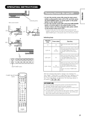
... the monitor on and off at short time intervals. Failures might result from the failure. ENGLISH OPERATING INSTRUCTIONS Main power switch Indicating lamp (32) (37) (42) SUB-POWER button POWER ON/OFF button Turning Power On and Off • To turn the monitor power ON, press the main power switch on...
... the monitor on and off at short time intervals. Failures might result from the failure. ENGLISH OPERATING INSTRUCTIONS Main power switch Indicating lamp (32) (37) (42) SUB-POWER button POWER ON/OFF button Turning Power On and Off • To turn the monitor power ON, press the main power switch on...
Owners Guide
Page 30
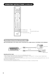
... normally. 30 The photo pictures will be displayed. OPERATING INSTRUCTIONS (continued) ROTATE button PHOTO button SLIDE SHOW button PHOTO INPUT button Photo Input Display (37/42 only) With the PHOTO button on the user manual of digital camera. *Insert the memory card when use the USB Card Reader. 3. USB cable Digital...
... normally. 30 The photo pictures will be displayed. OPERATING INSTRUCTIONS (continued) ROTATE button PHOTO button SLIDE SHOW button PHOTO INPUT button Photo Input Display (37/42 only) With the PHOTO button on the user manual of digital camera. *Insert the memory card when use the USB Card Reader. 3. USB cable Digital...

Owners Guide
Page 31
... previous input display during slide show of 90° ➝ 180° ➝ 270° ➝ 0°. ENGLISH OPERATING INSTRUCTIONS (continued) Photo Input Display (37/42 only) (continued) Photo Input Function Buttons on Remote Control Function PHOTO Display the pictures in "Slide Interval" of function menu. 39 1/ 6 5/ 6 2/ 6 6/ 6 3/ 6 4/ 6 Thumbnail-Size Image No...
... previous input display during slide show of 90° ➝ 180° ➝ 270° ➝ 0°. ENGLISH OPERATING INSTRUCTIONS (continued) Photo Input Display (37/42 only) (continued) Photo Input Function Buttons on Remote Control Function PHOTO Display the pictures in "Slide Interval" of function menu. 39 1/ 6 5/ 6 2/ 6 6/ 6 3/ 6 4/ 6 Thumbnail-Size Image No...

Owners Guide
Page 32
OPERATING INSTRUCTIONS (continued) Photo Input Display (37/42 only) (continued) CAUTION • The picture may not be displayed correctly, or it causes the malfunction. • Insert only one memory even though the USB ...
OPERATING INSTRUCTIONS (continued) Photo Input Display (37/42 only) (continued) CAUTION • The picture may not be displayed correctly, or it causes the malfunction. • Insert only one memory even though the USB ...
Owners Guide
Page 39
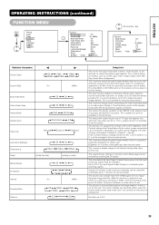
... it will continue for the period of this function is grayed out and not available in small amounts, at set intervals during slide show. (37/42 only) The original factory settings for this item is recommended to set to Extend 1 or 2, it will be controlled). This is always set intervals, to...
... it will continue for the period of this function is grayed out and not available in small amounts, at set intervals during slide show. (37/42 only) The original factory settings for this item is recommended to set to Extend 1 or 2, it will be controlled). This is always set intervals, to...

Owners Guide
Page 42
... On Magenta Magenta is strengthened. Green is weakened. Lightens red only. Enhances green and weakens red. Yellow Yellow is required to select with gray color. 42
... On Magenta Magenta is strengthened. Green is weakened. Lightens red only. Enhances green and weakens red. Yellow Yellow is required to select with gray color. 42
Owners Guide
Page 48
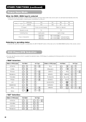
... sync signal Horizontal Vertical PC signal Operation mode Indicating lamp Power consumption Yes Yes Active (normal display) On Lights green 245W (32) 320W (37) 380W (42) No Yes No Yes No No Blank (no display) Off Lights orange 3W or less (RGB1) 1W or less (RGB2 ; 100V≤AC≤120V...
... sync signal Horizontal Vertical PC signal Operation mode Indicating lamp Power consumption Yes Yes Active (normal display) On Lights green 245W (32) 320W (37) 380W (42) No Yes No Yes No No Blank (no display) Off Lights orange 3W or less (RGB1) 1W or less (RGB2 ; 100V≤AC≤120V...
Owners Guide
Page 53
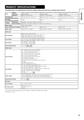
Panel Display dimensions Resolution Approx. 32 inches (716 (H) x 399 (V) mm, Approx. 37 inches (814 (H) x 445 (V) mm, Approx. 42 inches (922 (H) x 522 (V) mm, diagonal 820mm) diagonal 930mm) diagonal 1059mm) 852 (H) x 1024 (V) pixels 1024 (H) x 1024 (V) pixels 1024(H) x 1024 (V) pixels Net dimensions (excluding Speakers/Stand) Net ...
Panel Display dimensions Resolution Approx. 32 inches (716 (H) x 399 (V) mm, Approx. 37 inches (814 (H) x 445 (V) mm, Approx. 42 inches (922 (H) x 522 (V) mm, diagonal 820mm) diagonal 930mm) diagonal 1059mm) 852 (H) x 1024 (V) pixels 1024 (H) x 1024 (V) pixels 1024(H) x 1024 (V) pixels Net dimensions (excluding Speakers/Stand) Net ...


