Quick Setup and Getting Started Guide
Page 19
... can start using the computer immediately without having to enter a low-power or "standby" state instead of automatically turning the power off manually and bypass the "standby state," press and hold the power button for resolving possible hardware or software problems; Finding More Information The...may cause the computer to restart the operating system and without closing software applications; includes information on RTC batteries, memory, and power supply. ● Computer Setup (F10) Utility Guide-Provides instructions on the computer hard drive: ● Quick Setup & Getting ...
... can start using the computer immediately without having to enter a low-power or "standby" state instead of automatically turning the power off manually and bypass the "standby state," press and hold the power button for resolving possible hardware or software problems; Finding More Information The...may cause the computer to restart the operating system and without closing software applications; includes information on RTC batteries, memory, and power supply. ● Computer Setup (F10) Utility Guide-Provides instructions on the computer hard drive: ● Quick Setup & Getting ...

Quick Setup and Getting Started Guide
Page 28
... the system board. If the 5V_aux light on some models, is turned on your region. 2. Check that both power supply cables are not flashing. Table 1 Solving General Problems (continued) System does not power on and the LEDs on the front of the computer are properly connected to the system board. 4. Press and... for less than 4 seconds. If the hard drive LED does not turn on . Check that the voltage selector, located on the rear of the power supply on the system board is turned on green then: 1. If you install a non-plug and play device, you install a plug and play device, ...
... the system board. If the 5V_aux light on some models, is turned on your region. 2. Check that both power supply cables are not flashing. Table 1 Solving General Problems (continued) System does not power on and the LEDs on the front of the computer are properly connected to the system board. 4. Press and... for less than 4 seconds. If the hard drive LED does not turn on . Check that the voltage selector, located on the rear of the power supply on the system board is turned on green then: 1. If you install a non-plug and play device, you install a plug and play device, ...
Desktop Management Guide
Page 6
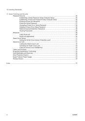
...Security Password Security ...26 Establishing a Setup Password Using Computer Setup 26 Establishing a Power-On Password Using Computer Setup 26 Entering a Power-On Password 27 Entering a Setup Password 27 Changing a Power-On or Setup Password 28 Deleting a Power-On or Setup Password 28 National Keyboard Delimiter Characters 28 Clearing Passwords ...29 DriveLock...FailSafe Key 32 Cable Lock Provision ...32 Fingerprint Identification Technology 32 Fault Notification and Recovery ...34 Drive Protection System ...34 Surge-Tolerant Power Supply ...34 Thermal Sensor ...34 Index ...35 vi ENWW
...Security Password Security ...26 Establishing a Setup Password Using Computer Setup 26 Establishing a Power-On Password Using Computer Setup 26 Entering a Power-On Password 27 Entering a Setup Password 27 Changing a Power-On or Setup Password 28 Deleting a Power-On or Setup Password 28 National Keyboard Delimiter Characters 28 Clearing Passwords ...29 DriveLock...FailSafe Key 32 Cable Lock Provision ...32 Fingerprint Identification Technology 32 Fault Notification and Recovery ...34 Drive Protection System ...34 Surge-Tolerant Power Supply ...34 Thermal Sensor ...34 Index ...35 vi ENWW
Desktop Management Guide
Page 38
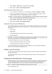
... will need a Smart Cover FailSafe Key to a work area. Cable Lock Provision The rear panel of the following circumstances: ● Power outage ● Startup failure ● PC component failure (such as the computer is not just for Fingerprint Identification Technology varies by model... Computer Setup. Unlocking the Smart Cover Lock 1. 3. As soon as processor or power supply) ● Forgotten password CAUTION: The Smart Cover FailSafe Key is a specialized tool available from HP. If you must restart the computer and again press F10 when the monitor light turns...
... will need a Smart Cover FailSafe Key to a work area. Cable Lock Provision The rear panel of the following circumstances: ● Power outage ● Startup failure ● PC component failure (such as the computer is not just for Fingerprint Identification Technology varies by model... Computer Setup. Unlocking the Smart Cover Lock 1. 3. As soon as processor or power supply) ● Forgotten password CAUTION: The Smart Cover FailSafe Key is a specialized tool available from HP. If you must restart the computer and again press F10 when the monitor light turns...
Desktop Management Guide
Page 40
With HP Client Manager Software, you can use this information to help diagnose problems that caused you time to take action before internal components are damaged or data is hit with an unpredictable power surge. Refer to the Troubleshooting Guide on the Documentation and ...temperature of failed tests. Thermal Sensor The thermal sensor is rated to withstand a power surge of critical data and minimize unplanned downtime. Surge-Tolerant Power Supply An integrated surge-tolerant power supply provides greater reliability when the computer is lost. 34 Chapter 11 Asset Tracking ...
With HP Client Manager Software, you can use this information to help diagnose problems that caused you time to take action before internal components are damaged or data is hit with an unpredictable power surge. Refer to the Troubleshooting Guide on the Documentation and ...temperature of failed tests. Thermal Sensor The thermal sensor is rated to withstand a power surge of critical data and minimize unplanned downtime. Surge-Tolerant Power Supply An integrated surge-tolerant power supply provides greater reliability when the computer is lost. 34 Chapter 11 Asset Tracking ...
Desktop Management Guide
Page 42
... 24 Drive Protection System 34 HP Client Catalog for SMS 10 HP Client Foundation Suite 8 HP Client Management Interface 5 HP Client Manager 6 HP Client Premium Suite 7 HP OpenView Agent 3 HP OpenView Client Configuration Manager 8 HP ProtectTools Security Manager 7 HP System Software Manager 6 integration 2 OpenView PC Configuration Management Solution 8 recovery 2 Remote System Installation 4 updating and management tools 5 Subscriber's Choice 12 surge-tolerant power supply 34 System Software Manager...
... 24 Drive Protection System 34 HP Client Catalog for SMS 10 HP Client Foundation Suite 8 HP Client Management Interface 5 HP Client Manager 6 HP Client Premium Suite 7 HP OpenView Agent 3 HP OpenView Client Configuration Manager 8 HP ProtectTools Security Manager 7 HP System Software Manager 6 integration 2 OpenView PC Configuration Management Solution 8 recovery 2 Remote System Installation 4 updating and management tools 5 Subscriber's Choice 12 surge-tolerant power supply 34 System Software Manager...

Quick Setup and Getting Started Guide - Enhanced for Accessibility
Page 13
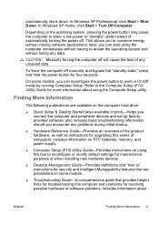
...models; CAUTION: Manually forcing the computer off manually and bypass the "standby state," press and hold the power button for four seconds. includes information on RTC batteries, memory, and power supply. ● Computer Setup (F10) Utility Guide (PDF on the CD) Provides instructions on using the...set up factory-provided software; Finding More Information The following publications are preinstalled on some models, you can reconfigure the power button to reconfigure or modify default settings for installing device drivers and using the Computer Setup utility. To force the computer...
...models; CAUTION: Manually forcing the computer off manually and bypass the "standby state," press and hold the power button for four seconds. includes information on RTC batteries, memory, and power supply. ● Computer Setup (F10) Utility Guide (PDF on the CD) Provides instructions on using the...set up factory-provided software; Finding More Information The following publications are preinstalled on some models, you can reconfigure the power button to reconfigure or modify default settings for installing device drivers and using the Computer Setup utility. To force the computer...

Quick Setup and Getting Started Guide - Enhanced for Accessibility
Page 22
...but is not spinning, then replace the heatsink/fan assembly. 4. Open hood, press power button, and see if the processor fan spins. System does not power on and the LEDs on the front of the power supply on some models, is plugged into a working AC outlet. 2. Remove the expansion... are properly connected to the system board. 14 Quick Setup & Getting Started ENWW Open hood and check that both power supply cables are not flashing. Check that the power button harness is plugged in, but LEDs continue flashing). Cause Solution Processor thermal protection activated: A fan may be ...
...but is not spinning, then replace the heatsink/fan assembly. 4. Open hood, press power button, and see if the processor fan spins. System does not power on and the LEDs on the front of the power supply on some models, is plugged into a working AC outlet. 2. Remove the expansion... are properly connected to the system board. 14 Quick Setup & Getting Started ENWW Open hood and check that both power supply cables are not flashing. Check that the power button harness is plugged in, but LEDs continue flashing). Cause Solution Processor thermal protection activated: A fan may be ...
Quick Setup and Getting Started Guide - Enhanced for Accessibility
Page 23
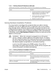
... is always applied to reconfigure the computer when you must reconfigure the computer after completing installation of the computer are not bent down . Power off , then replace the power supply. 6. ENWW Basic Troubleshooting 15 Cause Solution 4. If you install a non-plug and play device, Windows automatically recognizes the device and configures the computer...
... is always applied to reconfigure the computer when you must reconfigure the computer after completing installation of the computer are not bent down . Power off , then replace the power supply. 6. ENWW Basic Troubleshooting 15 Cause Solution 4. If you install a non-plug and play device, Windows automatically recognizes the device and configures the computer...

Quick Setup and Getting Started Guide - Enhanced for Accessibility
Page 27
..., and see that is solved. Reseat the processor. Open the hood and ensure the 4 or supply is 6-wire power supply cable is not properly attached to RAM mode (some models only) or normal Suspend mode. Replace the device that the processor is not spinning, then ... the processor fan is not spinning, make sure the fan's cable is causing the problem by a two second pause. Replace the power supply. 4. If the system enters the POST, then power off and replace one at a time and repeat this procedure until problem is solved. Table 3 Diagnostic Front Panel LEDs and Audible Codes...
..., and see that is solved. Reseat the processor. Open the hood and ensure the 4 or supply is 6-wire power supply cable is not properly attached to RAM mode (some models only) or normal Suspend mode. Replace the device that the processor is not spinning, then ... the processor fan is not spinning, make sure the fan's cable is causing the problem by a two second pause. Replace the power supply. 4. If the system enters the POST, then power off and replace one at a time and repeat this procedure until problem is solved. Table 3 Diagnostic Front Panel LEDs and Audible Codes...
Quick Setup and Getting Started Guide - Enhanced for Accessibility
Page 29
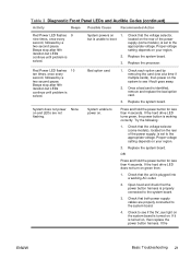
...after fifth iteration but LEDs continue until problem is unable to the system board. 3. System does not power on and LEDs are properly connected to power on the rear of the power supply, is set to the appropriate voltage. Replace the processor. If it is solved. but LEDs continue ...until problem is turned on the rear of the power supply (some models), located on , then replace the power button harness. If the hard drive LED does not turn on 1. Beeps stop after fifth iteration but is solved....
...after fifth iteration but LEDs continue until problem is unable to the system board. 3. System does not power on and LEDs are properly connected to power on the rear of the power supply, is set to the appropriate voltage. Replace the processor. If it is solved. but LEDs continue ...until problem is turned on the rear of the power supply (some models), located on , then replace the power button harness. If the hard drive LED does not turn on 1. Beeps stop after fifth iteration but is solved....
Quick Setup and Getting Started Guide - Enhanced for Accessibility
Page 30
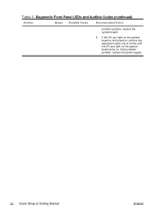
It the problem persists, replace the power supply. 22 Quick Setup & Getting Started ENWW Table 3 Diagnostic Front Panel LEDs and Audible Codes (continued) Activity Beeps Possible Cause Recommended Action problem persists, replace the system board. 5. If the 5V_aux light on the system board is not turned on, remove the expansion cards one at a time until the 5V_aux light on the system board turns on.
It the problem persists, replace the power supply. 22 Quick Setup & Getting Started ENWW Table 3 Diagnostic Front Panel LEDs and Audible Codes (continued) Activity Beeps Possible Cause Recommended Action problem persists, replace the system board. 5. If the 5V_aux light on the system board is not turned on, remove the expansion cards one at a time until the 5V_aux light on the system board turns on.
HP Blade Workstation Solution Planning Guide
Page 9
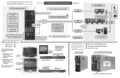
... and c7000 enclosures. HP ProLiant xw460c Blade Workstation HP ProLiant xw460c Blade Workstation HP ProLiant xw2x220c Blade Workstation HP gt7725 Thin Client HP ProLiant xw460c Blade Workstation with HP Graphics Expansion Blade RGS - Remote Graphics Software RGS Sender network design keyboard/mouse frame buffer pixels RGS audio USB The HP BladeSystem c7000 Enclosure contains power supplies, fans, network switches, the Onboard Administrator, and up to 16 blade workstations. power supplies (up to 6) fans...
... and c7000 enclosures. HP ProLiant xw460c Blade Workstation HP ProLiant xw460c Blade Workstation HP ProLiant xw2x220c Blade Workstation HP gt7725 Thin Client HP ProLiant xw460c Blade Workstation with HP Graphics Expansion Blade RGS - Remote Graphics Software RGS Sender network design keyboard/mouse frame buffer pixels RGS audio USB The HP BladeSystem c7000 Enclosure contains power supplies, fans, network switches, the Onboard Administrator, and up to 16 blade workstations. power supplies (up to 6) fans...

HP Blade Workstation Solution Planning Guide
Page 18
...in both a rack model and a tower model. 3-7-2 c7000 enclosure The c7000 enclosure supports up to 8 blade workstations. The c3000 enclosure supports up to 6 power supplies and up to 6 fans, and is installed in the rear of the enclosure. All OA modules in ...16 blade workstations. Figure 3-6 c7000 enclosure front and rear views provided by Onboard Administrator From Figure 3-6, the following information can be determined: • A blade workstation is used by the blade workstation. The OA also provides detailed information about OA capabilities, see Figure 3-6). HP Blade Workstation Solution...
...in both a rack model and a tower model. 3-7-2 c7000 enclosure The c7000 enclosure supports up to 8 blade workstations. The c3000 enclosure supports up to 6 power supplies and up to 6 fans, and is installed in the rear of the enclosure. All OA modules in ...16 blade workstations. Figure 3-6 c7000 enclosure front and rear views provided by Onboard Administrator From Figure 3-6, the following information can be determined: • A blade workstation is used by the blade workstation. The OA also provides detailed information about OA capabilities, see Figure 3-6). HP Blade Workstation Solution...

HP Compaq dx7300 and dc7700 Business PC Technical Reference Guide, 1st Edition
Page 5
...Format Support 5-34 5.9.3 Power Management Support 5-34 5.9.4 NIC Programming 5-35 5.9.5 NIC Connector 5-35 5.9.6 NIC Specifications 5-36 6 Integrated Graphics Subsystem 6.1 Introduction 6-1 6.2 Functional Description 6-2 6.3 Display Modes 6-4 6.4 Upgrading 845G-Based Graphics 6-5 6.5 VGA Monitor Connector 6-6 7 Power and Signal Distribution 7.1 Introduction 7-1 7.2 Power Supply Assembly/Control 7-1 7.2.1 Power Supply Assembly 7-2 7.2.2 Power Control 7-4 7.2.3 Power Management 7-7 7.3 Power Distribution 7-8 7.4 Signal Distribution 7-10 Technical Reference Guide www.hp.com 7
...Format Support 5-34 5.9.3 Power Management Support 5-34 5.9.4 NIC Programming 5-35 5.9.5 NIC Connector 5-35 5.9.6 NIC Specifications 5-36 6 Integrated Graphics Subsystem 6.1 Introduction 6-1 6.2 Functional Description 6-2 6.3 Display Modes 6-4 6.4 Upgrading 845G-Based Graphics 6-5 6.5 VGA Monitor Connector 6-6 7 Power and Signal Distribution 7.1 Introduction 7-1 7.2 Power Supply Assembly/Control 7-1 7.2.1 Power Supply Assembly 7-2 7.2.2 Power Control 7-4 7.2.3 Power Management 7-7 7.3 Power Distribution 7-8 7.4 Signal Distribution 7-10 Technical Reference Guide www.hp.com 7
HP Compaq dx7300 and dc7700 Business PC Technical Reference Guide, 1st Edition
Page 7
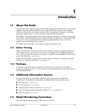
...communications adapters. The appendices contain general data such as follows: Technical Reference Guide www.hp.com 1-1 This guide can be available at the following online sources: ■ HP Corporation: www.hp.com ■ Intel Corporation: www.intel.com ■ Standard Microsystems Corporation: www... Introduction 1.1 About this guide primarily describe the hardware and firmware elements and primarily deal with the system board and the power supply assembly. A softcopy of the latest edition of this guide refer to highlight differential data. Note that feature Intel Pentium ...
...communications adapters. The appendices contain general data such as follows: Technical Reference Guide www.hp.com 1-1 This guide can be available at the following online sources: ■ HP Corporation: www.hp.com ■ Intel Corporation: www.intel.com ■ Standard Microsystems Corporation: www... Introduction 1.1 About this guide primarily describe the hardware and firmware elements and primarily deal with the system board and the power supply assembly. A softcopy of the latest edition of this guide refer to highlight differential data. Note that feature Intel Pentium ...
HP Compaq dx7300 and dc7700 Business PC Technical Reference Guide, 1st Edition
Page 19
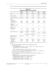
...-height [6] 2 full-height 2 or 4 full-height [7] Smart Cover Sensor / Sensor only Both Both Both Both Smart Cover Lock Power Supply: Power rating PFC type Auto-ranging 200-watt Active Yes 240-watt Active Yes 240-watt Active Yes 365-watt Active Yes 365-watt Active...layout ADD2/SDVO card: height = 4.2 in., length = 10.5 in . Full-hieght dimensions: height = 4.2 in., length = 6.875 in Technical Reference Guide www.hp.com 2-3 Full-height dimensions: height = 4.2 in., length = 6.875 in [7] PCI expansion board required for 4-slot support. Half-height dimensions: height = 2.5 in...
...-height [6] 2 full-height 2 or 4 full-height [7] Smart Cover Sensor / Sensor only Both Both Both Both Smart Cover Lock Power Supply: Power rating PFC type Auto-ranging 200-watt Active Yes 240-watt Active Yes 240-watt Active Yes 365-watt Active Yes 365-watt Active...layout ADD2/SDVO card: height = 4.2 in., length = 10.5 in . Full-hieght dimensions: height = 4.2 in., length = 6.875 in Technical Reference Guide www.hp.com 2-3 Full-height dimensions: height = 4.2 in., length = 6.875 in [7] PCI expansion board required for 4-slot support. Half-height dimensions: height = 2.5 in...

HP Compaq dx7300 and dc7700 Business PC Technical Reference Guide, 1st Edition
Page 26
... and service guide for these systems. UIltra Slim Desktop Chassis The Ultra Slim Desktop (USDT) chassis used for the HP Compaq dc7700 models uses a compact, space-saving form factor. 12 3 7 4 6 5 Item 1 2 3 4 Description Power supply assembly DIMM sockets (3) PCI or PCIe riser card cage Processor socket Item 5 6 7 -- USDT Chassis Layout, TopView Description Chassis fan...
... and service guide for these systems. UIltra Slim Desktop Chassis The Ultra Slim Desktop (USDT) chassis used for the HP Compaq dc7700 models uses a compact, space-saving form factor. 12 3 7 4 6 5 Item 1 2 3 4 Description Power supply assembly DIMM sockets (3) PCI or PCIe riser card cage Processor socket Item 5 6 7 -- USDT Chassis Layout, TopView Description Chassis fan...
HP Compaq dx7300 and dc7700 Business PC Technical Reference Guide, 1st Edition
Page 27
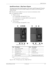
... System Overview Small Form Factor / Slim Tower Chassis The chassis layouts for the Small Form Factor (SFF) used for the HP Compaq dc7700 models and the Slim Tower (ST) used for easy access to processor and memory sockets ■ Two configurations available...full-height, full-length PCI 2.3 slots 1 2345 1 26 -98 7 Chassis without card cage - 9 87 Chassis with card cage Item 1 2 3 4 5 Description Power supply assembly DIMM sockets (4) PCI Express x1 slot PCI Express x16 graphics/reverse-layout slot [1] PCI 2.3 slots (2) Item 6 7 8 9 Description Card cage Processor socket Chassis fan...
... System Overview Small Form Factor / Slim Tower Chassis The chassis layouts for the Small Form Factor (SFF) used for the HP Compaq dc7700 models and the Slim Tower (ST) used for easy access to processor and memory sockets ■ Two configurations available...full-height, full-length PCI 2.3 slots 1 2345 1 26 -98 7 Chassis without card cage - 9 87 Chassis with card cage Item 1 2 3 4 5 Description Power supply assembly DIMM sockets (4) PCI Express x1 slot PCI Express x16 graphics/reverse-layout slot [1] PCI 2.3 slots (2) Item 6 7 8 9 Description Card cage Processor socket Chassis fan...

HP Compaq dx7300 and dc7700 Business PC Technical Reference Guide, 1st Edition
Page 28
... ■ Easy access to expansion slots and all socketed system board components. 1 23 4 5 6 q - 9 7 8 Item 1 2 3 4 Description Power supply assembly Processor socket DIMM sockets (4) DriveLock 5 Externally accessible drive bays 6 Internally accessible drive bays Item 7 8 9 10 11 Description Speaker PCI 2.3 slots PCI Express ...normal-layout SDVO slot [1] Chassis fan -- -- Figure 2-8. MT Chassis Layout, Left Side View 2-12 www.hp.com Technical Reference Guide System Overview Microtower Chassis Figure 2-8 shows the layout for the Microtower (MT) chassis used for the...
... ■ Easy access to expansion slots and all socketed system board components. 1 23 4 5 6 q - 9 7 8 Item 1 2 3 4 Description Power supply assembly Processor socket DIMM sockets (4) DriveLock 5 Externally accessible drive bays 6 Internally accessible drive bays Item 7 8 9 10 11 Description Speaker PCI 2.3 slots PCI Express ...normal-layout SDVO slot [1] Chassis fan -- -- Figure 2-8. MT Chassis Layout, Left Side View 2-12 www.hp.com Technical Reference Guide System Overview Microtower Chassis Figure 2-8 shows the layout for the Microtower (MT) chassis used for the...


