
Maintenance and Service Guide
Page 5
... 1 Product description ...1 2 External component identification ...3 Right side ...3 Left side ...4 Display ...6 Changing your notebook to an entertainment stand 7 Changing your notebook to a tablet 7 Top ...8 TouchPad ...8 Speakers ...8 Lights ...9 Keys ...10 Service label and PCID label ...11 Service label ...11 PCID label ...12 3 Illustrated parts catalog ...13 Computer major components ...13 Display assembly subcomponents ...17 Mass storage devices ...19 Miscellaneous parts ...19 Sequential part number listing ...19 4 Removal and replacement procedures preliminary requirements...
... 1 Product description ...1 2 External component identification ...3 Right side ...3 Left side ...4 Display ...6 Changing your notebook to an entertainment stand 7 Changing your notebook to a tablet 7 Top ...8 TouchPad ...8 Speakers ...8 Lights ...9 Keys ...10 Service label and PCID label ...11 Service label ...11 PCID label ...12 3 Illustrated parts catalog ...13 Computer major components ...13 Display assembly subcomponents ...17 Mass storage devices ...19 Miscellaneous parts ...19 Sequential part number listing ...19 4 Removal and replacement procedures preliminary requirements...

Maintenance and Service Guide
Page 6
5 Removal and replacement procedures for Authorized Service Provider parts 27 Component replacement procedures ...27 Bottom cover ...28 USB board ...32 WLAN module ...33 WWAN module ...35 Power button board ...37 Speakers ...38 Battery ...40 TouchPad ...42 Power connector cable ...43 System board ...44 Display assembly ...47 6 Using Setup Utility (BIOS) and HP PC Hardware Diagnostics (UEFI 55 Starting Setup Utility (BIOS) ...55 Updating the BIOS ...55 Determining the BIOS version ...55 Downloading a BIOS update ...56 Using HP PC Hardware Diagnostics (UEFI) ...57 Downloading HP PC Hardware ...
5 Removal and replacement procedures for Authorized Service Provider parts 27 Component replacement procedures ...27 Bottom cover ...28 USB board ...32 WLAN module ...33 WWAN module ...35 Power button board ...37 Speakers ...38 Battery ...40 TouchPad ...42 Power connector cable ...43 System board ...44 Display assembly ...47 6 Using Setup Utility (BIOS) and HP PC Hardware Diagnostics (UEFI 55 Starting Setup Utility (BIOS) ...55 Updating the BIOS ...55 Determining the BIOS version ...55 Downloading a BIOS update ...56 Using HP PC Hardware Diagnostics (UEFI) ...57 Downloading HP PC Hardware ...
Maintenance and Service Guide
Page 7
... + Gyroscope + e-Compass) Compatible with Miracast-certified devices Support Assistant GPS Integrated wireless local area network (WLAN) options by way of wireless module; 2 antennas Support for the following WWAN format: ● HP hs3110 HSPA+ Mobile Broadband Module SIM card slot (user accessible) 1 typical brightness: 200 nits (cd/m2) Supports low-voltage differential signaling (LVDS) (co-layout with eDP1.3+PSR) On-board system memory Support for DDR3L-1333 MHz (DDR3L-1600 MHz...
... + Gyroscope + e-Compass) Compatible with Miracast-certified devices Support Assistant GPS Integrated wireless local area network (WLAN) options by way of wireless module; 2 antennas Support for the following WWAN format: ● HP hs3110 HSPA+ Mobile Broadband Module SIM card slot (user accessible) 1 typical brightness: 200 nits (cd/m2) Supports low-voltage differential signaling (LVDS) (co-layout with eDP1.3+PSR) On-board system memory Support for DDR3L-1333 MHz (DDR3L-1600 MHz...

Maintenance and Service Guide
Page 8
... image sensor Taps enabled as default Multitouch gestures enabled Support for PS/2 and SMB interface Support for Windows 8.1 Modern TouchPad Gestures 1 meter length power cord AC adapter with localized cable plug support Support for the following AC adapter: ● 45 W HP Smart AC adapter (non-PFC, with push-push technology. Category External media cards Ports Keyboard/pointing devices Power requirements Security Operating system Serviceability Description HP Multi-Format Digital Media Card Reader with 26.5 mm z-height adapter [non-slim]) (not...
... image sensor Taps enabled as default Multitouch gestures enabled Support for PS/2 and SMB interface Support for Windows 8.1 Modern TouchPad Gestures 1 meter length power cord AC adapter with localized cable plug support Support for the following AC adapter: ● 45 W HP Smart AC adapter (non-PFC, with push-push technology. Category External media cards Ports Keyboard/pointing devices Power requirements Security Operating system Serviceability Description HP Multi-Format Digital Media Card Reader with 26.5 mm z-height adapter [non-slim]) (not...

Maintenance and Service Guide
Page 9
... network. ● On: The AC adapter is connected and the battery is charged. ● Off: The computer is firmly seated. Connects a network cable. ● White: The network is connected. ● Amber: Activity is occurring on the card it until it pops out. 2 External component identification Right side Component (1) SIM slot (select models only) (2) Memory card reader (3) USB 2.0 port (4) USB 3.0 port (5) HDMI port (6) RJ-45 (network) jack/status lights (7) AC adapter/battery light (8) Power connector Description Supports a wireless subscriber identity module...
... network. ● On: The AC adapter is connected and the battery is charged. ● Off: The computer is firmly seated. Connects a network cable. ● White: The network is connected. ● Amber: Activity is occurring on the card it until it pops out. 2 External component identification Right side Component (1) SIM slot (select models only) (2) Memory card reader (3) USB 2.0 port (4) USB 3.0 port (5) HDMI port (6) RJ-45 (network) jack/status lights (7) AC adapter/battery light (8) Power connector Description Supports a wireless subscriber identity module...

Maintenance and Service Guide
Page 10
... the Sleep state, a power- This jack does not support optional microphone-only devices. 4 Chapter 2 External component identification From the Start screen, type power, select Power and sleep settings, and then select Power and sleep from being mishandled or stolen. ● When the computer is off, press the button to the computer. Connects optional powered stereo speakers, headphones, earbuds, a headset, or a television audio cable. Also connects an optional headset microphone. The computer shuts off power to the display and...
... the Sleep state, a power- This jack does not support optional microphone-only devices. 4 Chapter 2 External component identification From the Start screen, type power, select Power and sleep settings, and then select Power and sleep from being mishandled or stolen. ● When the computer is off, press the button to the computer. Connects optional powered stereo speakers, headphones, earbuds, a headset, or a television audio cable. Also connects an optional headset microphone. The computer shuts off power to the display and...
Maintenance and Service Guide
Page 12
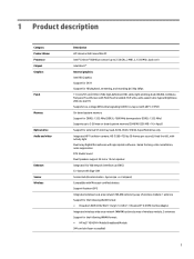
...). (2) Internal microphones (2) Record sound. (3) Webcam light On: The webcam is on. For optimal transmission, keep the areas immediately around the antennas free from the Start screen, type support, and then select the HP Support Assistant app. 6 Chapter 2 External component identification Display Component Description (1) WWAN antennas (2)* (select models only) Send and receive wireless signals to communicate with wireless local area networks (WLANs). (6) Windows button Returns you to video conference and chat online using streaming video. To use . (4) Webcam...
...). (2) Internal microphones (2) Record sound. (3) Webcam light On: The webcam is on. For optimal transmission, keep the areas immediately around the antennas free from the Start screen, type support, and then select the HP Support Assistant app. 6 Chapter 2 External component identification Display Component Description (1) WWAN antennas (2)* (select models only) Send and receive wireless signals to communicate with wireless local area networks (WLANs). (6) Windows button Returns you to video conference and chat online using streaming video. To use . (4) Webcam...
Maintenance and Service Guide
Page 17
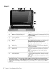
... that is the alphanumeric identifier used to locate documents, drivers, and support for the computer. ● Model (4). The part number helps a service technician to each product. ● Part number/Product number (p/n) (2). This number provides specific information about the product's hardware components. Service label and PCID label Service label When ordering parts or requesting information, provide the computer serial number and model description provided on the service label. ● Serial number (s/n) (1). This describes the duration...
... that is the alphanumeric identifier used to locate documents, drivers, and support for the computer. ● Model (4). The part number helps a service technician to each product. ● Part number/Product number (p/n) (2). This number provides specific information about the product's hardware components. Service label and PCID label Service label When ordering parts or requesting information, provide the computer serial number and model description provided on the service label. ● Serial number (s/n) (1). This describes the duration...

Maintenance and Service Guide
Page 18
The label may have a different number of characters depending on the operating system on the computer The PCID lable is located inside the bottom case. Windows 8 models Non-Windows 8 models 12 Chapter 2 External component identification PCID label The PCID label provides the information required to properly reset the notebook firmware (BIOS) back to factory shipped specifications when replacing the system board.
The label may have a different number of characters depending on the operating system on the computer The PCID lable is located inside the bottom case. Windows 8 models Non-Windows 8 models 12 Chapter 2 External component identification PCID label The PCID label provides the information required to properly reset the notebook firmware (BIOS) back to factory shipped specifications when replacing the system board.
Maintenance and Service Guide
Page 22
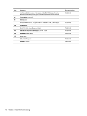
... N2840 processor, 2 GB memory, 32G eMMC, WWAN support, and the Windows 8.1 Standard operating system (includes replacement thermal material) Thermal plate (not spared) WLAN module: Broadcom BCM43142 802.11 b/g/n 1x1 Wi-Fi + Bluetooth 4.0 HMC Combo Adapter WWAN module: HP hs3110 HSPA+ Mobile Broadband Module Embedded 3 cell prismatic battery pack, 43 Wh, 3.82 Ah USB board (includes cable) Bottom cover Without WWAN support With WWAN support Spare part number 794300-501 753076...
... N2840 processor, 2 GB memory, 32G eMMC, WWAN support, and the Windows 8.1 Standard operating system (includes replacement thermal material) Thermal plate (not spared) WLAN module: Broadcom BCM43142 802.11 b/g/n 1x1 Wi-Fi + Bluetooth 4.0 HMC Combo Adapter WWAN module: HP hs3110 HSPA+ Mobile Broadband Module Embedded 3 cell prismatic battery pack, 43 Wh, 3.82 Ah USB board (includes cable) Bottom cover Without WWAN support With WWAN support Spare part number 794300-501 753076...
Maintenance and Service Guide
Page 33
... location during removal and replacement. There are as many as 76 screws that must be accessed by an authorized service provider. Component replacement procedures This chapter provides removal and replacement procedures for your computer, go to http://partsurfer.hp.com, select your country or region, and then follow the on supported parts for Authorized Service Provider only parts. NOTE: HP continually improves and changes product parts. Accessing...
... location during removal and replacement. There are as many as 76 screws that must be accessed by an authorized service provider. Component replacement procedures This chapter provides removal and replacement procedures for your computer, go to http://partsurfer.hp.com, select your country or region, and then follow the on supported parts for Authorized Service Provider only parts. NOTE: HP continually improves and changes product parts. Accessing...

Maintenance and Service Guide
Page 39
... shut it down through the operating system. 2. Turn off or in your country or region. NOTE: The WLAN antenna cable connects to the system board. (The WLAN module tilts up.) Component replacement procedures 33 If you replace the module and then receive a warning message, remove the module to restore device functionality, and then contact technical support. Remove the WLAN module: 1. Disconnect all external devices from the terminal on page...
... shut it down through the operating system. 2. Turn off or in your country or region. NOTE: The WLAN antenna cable connects to the system board. (The WLAN module tilts up.) Component replacement procedures 33 If you replace the module and then receive a warning message, remove the module to restore device functionality, and then contact technical support. Remove the WLAN module: 1. Disconnect all external devices from the terminal on page...

Maintenance and Service Guide
Page 41
Remove the WWAN module: 1. The blue WWAN antenna cable is connected to the WWAN module "Main" terminal. Description HP hs3110 HSPA+ Mobile Broadband Module Spare part number 748599-005 Before removing the WWAN module, follow these steps: 1. Disconnect all external devices from the computer. 3. Component replacement procedures 35 WWAN module NOTE: The WWAN module and the WLAN module are unsure whether the computer is off the computer. Turn off...
Remove the WWAN module: 1. The blue WWAN antenna cable is connected to the WWAN module "Main" terminal. Description HP hs3110 HSPA+ Mobile Broadband Module Spare part number 748599-005 Before removing the WWAN module, follow these steps: 1. Disconnect all external devices from the computer. 3. Component replacement procedures 35 WWAN module NOTE: The WWAN module and the WLAN module are unsure whether the computer is off the computer. Turn off...
Maintenance and Service Guide
Page 53
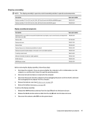
... computer by first unplugging the power cord from the AC outlet and then unplugging the AC adapter from the clips (1) built into the base enclosure. 3. Component replacement procedures 47 Disconnect all external devices connected to the computer. 3. Shut down through the operating system. 2. Release the WLAN wireless antenna cable from the system board. Remove the battery (see Bottom cover on page 40). If...
... computer by first unplugging the power cord from the AC outlet and then unplugging the AC adapter from the clips (1) built into the base enclosure. 3. Component replacement procedures 47 Disconnect all external devices connected to the computer. 3. Shut down through the operating system. 2. Release the WLAN wireless antenna cable from the system board. Remove the battery (see Bottom cover on page 40). If...
Maintenance and Service Guide
Page 61
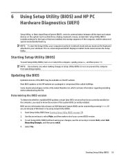
... you need to your computer must be in Setup Utility (BIOS). To exit Setup Utility (BIOS) without saving your current BIOS version. 3. Setup Utility (BIOS) includes settings for the types of devices installed, the startup sequence of the computer, and the amount of your changes, use the keyboard attached to know the version of the system BIOS currently installed. Starting Setup Utility (BIOS) 55 NOTE: To start Setup Utility (BIOS), turn on the HP website. NOTE: Use extreme care when making changes in notebook mode and...
... you need to your computer must be in Setup Utility (BIOS). To exit Setup Utility (BIOS) without saving your current BIOS version. 3. Setup Utility (BIOS) includes settings for the types of devices installed, the startup sequence of the computer, and the amount of your changes, use the keyboard attached to know the version of the system BIOS currently installed. Starting Setup Utility (BIOS) 55 NOTE: To start Setup Utility (BIOS), turn on the HP website. NOTE: Use extreme care when making changes in notebook mode and...
Maintenance and Service Guide
Page 62
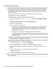
... may need to access this information to a network, consult the network administrator before installing any software updates, especially system BIOS updates. From the Start screen, type file, and then select File Explorer. 2. The BIOS installation begins. 5. Double-click the file that has an .exe extension (for HP updates now. 3. NOTE: After a message on battery power, docked in an optional docking device, or connected to the computer or an unsuccessful installation, download and install a BIOS update only...
... may need to access this information to a network, consult the network administrator before installing any software updates, especially system BIOS updates. From the Start screen, type file, and then select File Explorer. 2. The BIOS installation begins. 5. Double-click the file that has an .exe extension (for HP updates now. 3. NOTE: After a message on battery power, docked in an optional docking device, or connected to the computer or an unsuccessful installation, download and install a BIOS update only...
Maintenance and Service Guide
Page 63
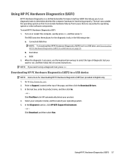
... caused by the operating system or other software components. Downloading HP PC Hardware Diagnostics (UEFI) to a USB device on or restart the computer, quickly press esc, and then press f2. Click Find Now to determine whether the computer hardware is a Unified Extensible Firmware Interface (UEFI) that are provided in the following order: a. When the diagnostic tool opens, use the keyboard arrow keys to run diagnostic...
... caused by the operating system or other software components. Downloading HP PC Hardware Diagnostics (UEFI) to a USB device on or restart the computer, quickly press esc, and then press f2. Click Find Now to determine whether the computer hardware is a Unified Extensible Firmware Interface (UEFI) that are provided in the following order: a. When the diagnostic tool opens, use the keyboard arrow keys to run diagnostic...
Maintenance and Service Guide
Page 65
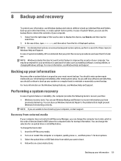
... the HP Recovery media. 2. Select the optical drive or USB flash drive from starting correctly. Backing up your initial backup immediately after a system failure is the order of devices listed in BIOS where the computer looks for later use. Swipe from the right edge of system instability, HP recommends that might prevent Windows from which is as good as installing software, running utilities, or changing Windows settings. In case of the touch screen to display...
... the HP Recovery media. 2. Select the optical drive or USB flash drive from starting correctly. Backing up your initial backup immediately after a system failure is the order of devices listed in BIOS where the computer looks for later use. Swipe from the right edge of system instability, HP recommends that might prevent Windows from which is as good as installing software, running utilities, or changing Windows settings. In case of the touch screen to display...

Maintenance and Service Guide
Page 71
... guidelines 26 esc key, identifying 10 Ethernet, product description 1 external media cards, product description 2 F fn key, identifying 10 G graphics, product description 1 grounding guidelines 24 guidelines equipment 26 grounding 24 packaging 25 transporting 25 workstation 25 H hard drive precautions 23 HDMI port identifying 3 HDMI to VGA adapter, spare part numbers 19 hinge covers removing 49 HP PC Hardware Diagnostics (UEFI) downloading 57 using 57 HP Recovery Manager correcting boot problems 59 I internal display switch, identifying 6 internal microphone, identifying 6 Index 65
... guidelines 26 esc key, identifying 10 Ethernet, product description 1 external media cards, product description 2 F fn key, identifying 10 G graphics, product description 1 grounding guidelines 24 guidelines equipment 26 grounding 24 packaging 25 transporting 25 workstation 25 H hard drive precautions 23 HDMI port identifying 3 HDMI to VGA adapter, spare part numbers 19 hinge covers removing 49 HP PC Hardware Diagnostics (UEFI) downloading 57 using 57 HP Recovery Manager correcting boot problems 59 I internal display switch, identifying 6 internal microphone, identifying 6 Index 65
Maintenance and Service Guide
Page 72
...1 chipset 1 display panel 1 Ethernet 1 external media cards 2 graphics 1 memory 1 microphone 1 operating system 2 optical drive 1 ports 2 power requirements 2 processors 1 product name 1 security 2 serviceability 2 video 1 wireless 1 product name 1 proximity sensor board removing 47, 51 spare part number 18, 20, 47 R rear feet removal 28 spare part number 28 recovery 60 refresh 60 removal/replacement procedures 27 RJ-45 (network) jack, identifying 3 RJ-45 (network) status lights, identifying 3 Rubber Feet Kit, spare part number 19, 20 S Screw Kit, spare part number 19, 20 security cable slot...
...1 chipset 1 display panel 1 Ethernet 1 external media cards 2 graphics 1 memory 1 microphone 1 operating system 2 optical drive 1 ports 2 power requirements 2 processors 1 product name 1 security 2 serviceability 2 video 1 wireless 1 product name 1 proximity sensor board removing 47, 51 spare part number 18, 20, 47 R rear feet removal 28 spare part number 28 recovery 60 refresh 60 removal/replacement procedures 27 RJ-45 (network) jack, identifying 3 RJ-45 (network) status lights, identifying 3 Rubber Feet Kit, spare part number 19, 20 S Screw Kit, spare part number 19, 20 security cable slot...


