HP Mini 1104 - Maintenance and Service Guide
Page 49
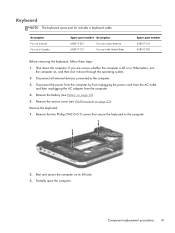
... United States Spare part number 658517-161 658517-001 Before removing the keyboard, follow these steps: 1. Remove the battery (see WLAN module on page 30). 5. Remove the two Phillips PM2.0×5.0 screws that secure the keyboard to the computer. 3. Rest and secure the computer on...Component replacement procedures 41 Remove the keyboard: 1. Disconnect the power from the computer by first unplugging the power cord from the AC outlet and then unplugging the AC adapter from the computer. 4. Keyboard NOTE: The keyboard spare part kit includes a keyboard cable. Description For ...
... United States Spare part number 658517-161 658517-001 Before removing the keyboard, follow these steps: 1. Remove the battery (see WLAN module on page 30). 5. Remove the two Phillips PM2.0×5.0 screws that secure the keyboard to the computer. 3. Rest and secure the computer on...Component replacement procedures 41 Remove the keyboard: 1. Disconnect the power from the computer by first unplugging the power cord from the AC outlet and then unplugging the AC adapter from the computer. 4. Keyboard NOTE: The keyboard spare part kit includes a keyboard cable. Description For ...
HP Mini 1104 - Maintenance and Service Guide
Page 50
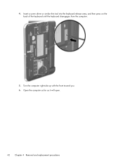
Insert a screw driver or similar thin tool into the keyboard release area, and then press on the back of the keyboard until the keyboard disengages from the computer. 5. Open the computer as far as it will open. 42 Chapter 4 Removal and replacement procedures Turn the computer right-side up with the front toward you. 6. 4.
Insert a screw driver or similar thin tool into the keyboard release area, and then press on the back of the keyboard until the keyboard disengages from the computer. 5. Open the computer as far as it will open. 42 Chapter 4 Removal and replacement procedures Turn the computer right-side up with the front toward you. 6. 4.
HP Mini 1104 - Maintenance and Service Guide
Page 51
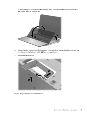
Component replacement procedures 43 Lift the rear edge of the keyboard (1), and then swing the keyboard (2) up and forward until it rests upside down on the palm rest. 8. Reverse this procedure to which the keyboard cable is attached, and then disconnect the keyboard cable (2) from the system board. 9. Release the zero insertion force (ZIF) connector (1) to install the keyboard. Remove the keyboard (3). 7.
Component replacement procedures 43 Lift the rear edge of the keyboard (1), and then swing the keyboard (2) up and forward until it rests upside down on the palm rest. 8. Reverse this procedure to which the keyboard cable is attached, and then disconnect the keyboard cable (2) from the system board. 9. Release the zero insertion force (ZIF) connector (1) to install the keyboard. Remove the keyboard (3). 7.
HP Mini 1104 - Maintenance and Service Guide
Page 52
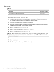
... from the defective top cover and install them on , and then shut it down the computer. Remove the top cover: 1. If you . 44 Chapter 4 Removal and replacement procedures Top cover NOTE: Description Top cover (includes TouchPad board and bracket) Spare part ...001 Before removing the top cover, follow these steps: 1. Remove the service cover (see WLAN module on page 50 for speaker removal and replacement instructions. See Speakers on page 32). 6. Shut down through the operating system. 2. Remove the battery (see Keyboard on page 30). 5. Remove the keyboard (see Battery...
... from the defective top cover and install them on , and then shut it down the computer. Remove the top cover: 1. If you . 44 Chapter 4 Removal and replacement procedures Top cover NOTE: Description Top cover (includes TouchPad board and bracket) Spare part ...001 Before removing the top cover, follow these steps: 1. Remove the service cover (see WLAN module on page 50 for speaker removal and replacement instructions. See Speakers on page 32). 6. Shut down through the operating system. 2. Remove the battery (see Keyboard on page 30). 5. Remove the keyboard (see Battery...
HP Mini 1104 - Maintenance and Service Guide
Page 58
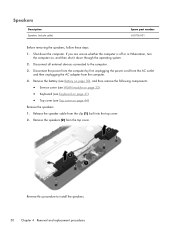
...the computer is off or in Hibernation, turn the computer on page 44) Remove the speakers: 1. Disconnect all external devices connected to install the speakers. 50 Chapter 4 Removal and replacement procedures Remove the speakers (2) from the clip (1) built into the top cover. 2. ... number 650736-001 Before removing the speakers, follow these steps: 1. Shut down through the operating system. 2. Remove the battery (see Battery on page 30), and then remove the following components: ● Service cover (see WLAN module on page 32) ● Keyboard (see Keyboard on page 41) &#...
...the computer is off or in Hibernation, turn the computer on page 44) Remove the speakers: 1. Disconnect all external devices connected to install the speakers. 50 Chapter 4 Removal and replacement procedures Remove the speakers (2) from the clip (1) built into the top cover. 2. ... number 650736-001 Before removing the speakers, follow these steps: 1. Shut down through the operating system. 2. Remove the battery (see Battery on page 30), and then remove the following components: ● Service cover (see WLAN module on page 32) ● Keyboard (see Keyboard on page 41) &#...
HP Mini 1104 - Maintenance and Service Guide
Page 59
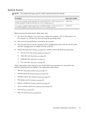
... board NOTE: The system board spare part kit includes replacement thermal material. includes processor) Spare part number 665231-001 665230-001 Before removing the system board, follow these steps: 1. Disconnect all external devices connected to the computer. 3. Disconnect the power from the computer ... components: ● Service cover (see WLAN module on page 32) ● Hard drive (see Hard drive on page 39) ● Keyboard (see Keyboard on page 41) ● Top cover (see Heat sink on computer models equipped with an Intel Atom N2600 1.60-GHz processor and WWAN capability...
... board NOTE: The system board spare part kit includes replacement thermal material. includes processor) Spare part number 665231-001 665230-001 Before removing the system board, follow these steps: 1. Disconnect all external devices connected to the computer. 3. Disconnect the power from the computer ... components: ● Service cover (see WLAN module on page 32) ● Hard drive (see Hard drive on page 39) ● Keyboard (see Keyboard on page 41) ● Top cover (see Heat sink on computer models equipped with an Intel Atom N2600 1.60-GHz processor and WWAN capability...
HP Mini 1104 - Maintenance and Service Guide
Page 62
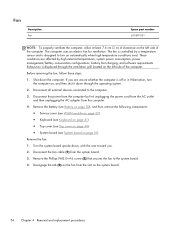
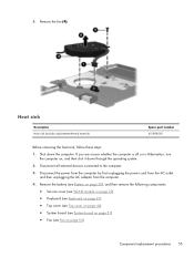
...turn on automatically when high temperature conditions exist. Before removing the fan, follow these steps: 1. Remove the battery (see Battery on page 30), and then remove the following components: ● Service cover (see WLAN module on page 32) ● Keyboard (see Keyboard on page 41) ● Top cover (see... Top cover on page 44) ● System board (see System board on the system board. 54 Chapter 4 Removal and replacement procedures The fan is controlled by a temperature sensor...
...turn on automatically when high temperature conditions exist. Before removing the fan, follow these steps: 1. Remove the battery (see Battery on page 30), and then remove the following components: ● Service cover (see WLAN module on page 32) ● Keyboard (see Keyboard on page 41) ● Top cover (see... Top cover on page 44) ● System board (see System board on the system board. 54 Chapter 4 Removal and replacement procedures The fan is controlled by a temperature sensor...
HP Mini 1104 - Maintenance and Service Guide
Page 63
... the operating system. 2. Disconnect all external devices connected to the computer. 3. Remove the battery (see Battery on page 30), and then remove the following components: ● Service cover (see WLAN module on page 32) ● Keyboard (see Keyboard on page 41) ● Top cover (see Top cover on page 44)... If you are unsure whether the computer is off or in Hibernation, turn the computer on page 54) Component replacement procedures 55 5. Remove the fan (4). Disconnect the power from the computer by first unplugging the power cord from the AC outlet and then unplugging the AC ...
... the operating system. 2. Disconnect all external devices connected to the computer. 3. Remove the battery (see Battery on page 30), and then remove the following components: ● Service cover (see WLAN module on page 32) ● Keyboard (see Keyboard on page 41) ● Top cover (see Top cover on page 44)... If you are unsure whether the computer is off or in Hibernation, turn the computer on page 54) Component replacement procedures 55 5. Remove the fan (4). Disconnect the power from the computer by first unplugging the power cord from the AC outlet and then unplugging the AC ...
HP Mini 1104 - Maintenance and Service Guide
Page 65
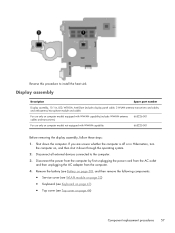
... steps: 1. Reverse this procedure to the computer. 3. Shut down through the operating system. 2. Remove the battery (see Battery on page 30), and then remove the following components: ● Service cover (see WLAN module on page 32) ● Keyboard (see Keyboard on page 41) ● Top cover (see Top cover on , and then shut it...
... steps: 1. Reverse this procedure to the computer. 3. Shut down through the operating system. 2. Remove the battery (see Battery on page 30), and then remove the following components: ● Service cover (see WLAN module on page 32) ● Keyboard (see Keyboard on page 41) ● Top cover (see Top cover on , and then shut it...
HP Mini 1104 - Maintenance and Service Guide
Page 82
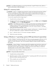
... For contact information, refer to http://www.hp.com/support, select your operating system and programs...NOTE: If the HP Recovery partition is displayed at the bottom of the HP Recovery partition: click ... in Help and Support. If the HP Recovery partition is listed, restart the ... tool reinstalls the operating system and HP programs and drivers that were installed at... created and any software installed on the computer are permanently removed. To initiate recovery using f11: 1. To recover the... installed on the computer are permanently removed. NOTE: For additional information on ...
... For contact information, refer to http://www.hp.com/support, select your operating system and programs...NOTE: If the HP Recovery partition is displayed at the bottom of the HP Recovery partition: click ... in Help and Support. If the HP Recovery partition is listed, restart the ... tool reinstalls the operating system and HP programs and drivers that were installed at... created and any software installed on the computer are permanently removed. To initiate recovery using f11: 1. To recover the... installed on the computer are permanently removed. NOTE: For additional information on ...
HP Mini 1104 - Maintenance and Service Guide
Page 89
... part number 18, 60 J jacks audio-in 11 audio-out 11 headphone 11 microphone 11 network 11 RJ-45 11 K key components 5 keyboard product description 3 removal 41 spare part numbers 16, 22, 41 keys Action 5 fn 5 Windows applications 5 Windows logo 5 L left-side components 10 light components... product description 3 ports external monitor 10 monitor port 10 product description 3 USB 10, 11 power button 7 power connector 10 power connector cable removal 53 spare part number 16, 21, 53 power cord set requirements 76 spare part numbers 19, 21 power light 8 power requirements, product description...
... part number 18, 60 J jacks audio-in 11 audio-out 11 headphone 11 microphone 11 network 11 RJ-45 11 K key components 5 keyboard product description 3 removal 41 spare part numbers 16, 22, 41 keys Action 5 fn 5 Windows applications 5 Windows logo 5 L left-side components 10 light components... product description 3 ports external monitor 10 monitor port 10 product description 3 USB 10, 11 power button 7 power connector 10 power connector cable removal 53 spare part number 16, 21, 53 power cord set requirements 76 spare part numbers 19, 21 power light 8 power requirements, product description...


