
Service Guide
Page 34
... models 502578-001 Rubber display bezel kits (contains all rubber pieces for use in computers with AMD 497183-001 processors (includes display panel cable) (5) Display inverter (includes Mylar shield) 486736-001 (6) Wireless Antenna Kits ● For use with standard display assemblies ● For use with Flush Glass display assemblies 489068-001...
... models 502578-001 Rubber display bezel kits (contains all rubber pieces for use in computers with AMD 497183-001 processors (includes display panel cable) (5) Display inverter (includes Mylar shield) 486736-001 (6) Wireless Antenna Kits ● For use with standard display assemblies ● For use with Flush Glass display assemblies 489068-001...
Service Guide
Page 47
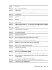
...-001 486850-001 486851-001 486852-001 486853-001 486872-001 486873-001 486874-001 486875-001 486876-001 486877-001 486878-001 Description Display inverter (includes Mylar shield) Fingerprint reader Top cover (includes TouchPad and TouchPad cable) for use with standard computer models equipped with a fingerprint reader (includes fingerprint reader...
...-001 486850-001 486851-001 486852-001 486853-001 486872-001 486873-001 486874-001 486875-001 486876-001 486877-001 486878-001 Description Display inverter (includes Mylar shield) Fingerprint reader Top cover (includes TouchPad and TouchPad cable) for use with standard computer models equipped with a fingerprint reader (includes fingerprint reader...

Service Guide
Page 88
..., WXGA, BrightView LED display panel for use in computers with AMD processors (includes display panel cable) 483261-001 483262-001 497182-001 497183-001 Display inverter (includes Mylar shield) 486736-001 Wireless Antenna Kits 80 Chapter 4 Removal and replacement procedures Reverse this procedure to install the SIM connector board.
..., WXGA, BrightView LED display panel for use in computers with AMD processors (includes display panel cable) 483261-001 483262-001 497182-001 497183-001 Display inverter (includes Mylar shield) 486736-001 Wireless Antenna Kits 80 Chapter 4 Removal and replacement procedures Reverse this procedure to install the SIM connector board.

Service Guide
Page 92
... the display panel cable and the backlight cable allow. 84 Chapter 4 Removal and replacement procedures If it is necessary to replace the standard display inverter, release the display inverter (1) from the display enclosure. 3. Flex the inside edges of the top (1) and sides (2) of the standard display assembly internal components, remove the following...
... the display panel cable and the backlight cable allow. 84 Chapter 4 Removal and replacement procedures If it is necessary to replace the standard display inverter, release the display inverter (1) from the display enclosure. 3. Flex the inside edges of the top (1) and sides (2) of the standard display assembly internal components, remove the following...

Service Guide
Page 93
....5×6.0 screws (1), and the four Phillips PM2.5×4.0 screws (2) that secure the display panel to the display enclosure. 8. Remove the display inverter. 7. Disconnect the display panel cable (3) from the display inverter. 6. Disconnect the display panel cable (2) and the backlight cable (3) from the display panel. If it is necessary to the display panel...
....5×6.0 screws (1), and the four Phillips PM2.5×4.0 screws (2) that secure the display panel to the display enclosure. 8. Remove the display inverter. 7. Disconnect the display panel cable (3) from the display inverter. 6. Disconnect the display panel cable (2) and the backlight cable (3) from the display panel. If it is necessary to the display panel...
Service Guide
Page 97
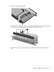
Remove the display panel cable (4). 13. Component replacement procedures 89 Release the inverter from the display assembly, and lift as far as the attached cables will allow (1). If it is necessary to replace the inverter, remove the four Phillips PM2.5×4.0 screws (1) that secure the inverter cover to the display assembly, and remove the inverter cover (2). 14. 12.
Remove the display panel cable (4). 13. Component replacement procedures 89 Release the inverter from the display assembly, and lift as far as the attached cables will allow (1). If it is necessary to replace the inverter, remove the four Phillips PM2.5×4.0 screws (1) that secure the inverter cover to the display assembly, and remove the inverter cover (2). 14. 12.

Service Guide
Page 98
... 4 Removal and replacement procedures Remove the wireless antenna cables from the display enclosure. 21. Disconnect the backlight cable (2), and the display panel cable (3) from the inverter. 16.
... 4 Removal and replacement procedures Remove the wireless antenna cables from the display enclosure. 21. Disconnect the backlight cable (2), and the display panel cable (3) from the inverter. 16.

Service Guide
Page 162
Where used: Two screws that secure the camera/microphone module to the Flush Glass display assembly Where used: Four screws that secure the inverter cover to the Flush Glass display assembly Where used: Six screws that secure the hinge to the Flush Glass display assembly 154 Chapter 7 Screw listing
Where used: Two screws that secure the camera/microphone module to the Flush Glass display assembly Where used: Four screws that secure the inverter cover to the Flush Glass display assembly Where used: Six screws that secure the hinge to the Flush Glass display assembly 154 Chapter 7 Screw listing

Service Guide
Page 187
Remove the display panel assembly (2) from the display inverter and remove the inverter (2). 5. Use a sharp-edged tool to cut the tape (1) that secure the display panel frame to the display panel. 9. Turn the display panel assembly upside down. 8. Display 179 4. Remove all screws that secures the sides of the display panel to the display enclosure. 6. Disconnect all screws (1) that secure the display panel assembly to the display panel frame. Remove all display panel cables (1) from the display enclosure. 7.
Remove the display panel assembly (2) from the display inverter and remove the inverter (2). 5. Use a sharp-edged tool to cut the tape (1) that secure the display panel frame to the display panel. 9. Turn the display panel assembly upside down. 8. Display 179 4. Remove all screws that secures the sides of the display panel to the display enclosure. 6. Disconnect all screws (1) that secure the display panel assembly to the display panel frame. Remove all display panel cables (1) from the display enclosure. 7.
Service Guide
Page 192
... spare part numbers 26, 81 display hinge removal 86 spare part number 26, 80, 86 Display Hinge Kit, spare part number 26, 80, 86 display inverter illustrated 25 spare part number 26, 80 display panel illustrated 25 product description 3 removal 85 spare part number 26, 80, 85 display specifications 127 display...
... spare part numbers 26, 81 display hinge removal 86 spare part number 26, 80, 86 Display Hinge Kit, spare part number 26, 80, 86 display inverter illustrated 25 spare part number 26, 80 display panel illustrated 25 product description 3 removal 85 spare part number 26, 80, 85 display specifications 127 display...
Service Guide
Page 193
internal digital dual array microphones, identifying 14 internal display switch, identifying 14 interrupt specifications 132, 133 inverter illustrated 25 spare part number 26, 80 J jacks audio-in (microphone) 15 audio-out (headphone) 15 RJ-11 (modem) 16 RJ-45 (network 17 TV ...
internal digital dual array microphones, identifying 14 internal display switch, identifying 14 interrupt specifications 132, 133 inverter illustrated 25 spare part number 26, 80 J jacks audio-in (microphone) 15 audio-out (headphone) 15 RJ-11 (modem) 16 RJ-45 (network 17 TV ...


