Service Guide
Page 6
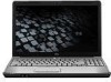
... ...57 Hard drive ...59 WLAN module ...62 WWAN module ...65 Memory module ...67 RTC battery ...69 Camera/microphone module for standard display assembly 70 Keyboard ...72 Keyboard cover ...74 Bluetooth module ...76 Speaker assembly ...77 SIM connector board ...79 Display assembly ...80 Standard display assembly 84 Flush Glass display assembly 87 Top...
... ...57 Hard drive ...59 WLAN module ...62 WWAN module ...65 Memory module ...67 RTC battery ...69 Camera/microphone module for standard display assembly 70 Keyboard ...72 Keyboard cover ...74 Bluetooth module ...76 Speaker assembly ...77 SIM connector board ...79 Display assembly ...80 Standard display assembly 84 Flush Glass display assembly 87 Top...

Service Guide
Page 14
...; RJ-45 (Ethernet, includes link and √ activity lights) USB (3) √ VGA (Dsub 15-pin) √ Docking Expansion port 3 supports HP xb4 √ Docking Station and HP Notebook QuickDock Keyboard/TouchPad 14.1-inch keyboard √ TouchPad (supports 2-way scroll √ with legend) Intel processors with UMA graphics subsystem AMD processors with UMA graphics subsystem...
...; RJ-45 (Ethernet, includes link and √ activity lights) USB (3) √ VGA (Dsub 15-pin) √ Docking Expansion port 3 supports HP xb4 √ Docking Station and HP Notebook QuickDock Keyboard/TouchPad 14.1-inch keyboard √ TouchPad (supports 2-way scroll √ with legend) Intel processors with UMA graphics subsystem AMD processors with UMA graphics subsystem...

Service Guide
Page 30
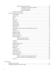
... 508119-xx1 For use in blue-colored computer models 508120-xx1 For use in blue-colored computer models only in the United States 507319-001 Keyboard covers ● For use with standard computer models ● For use with bronze-colored computer models ● For use with standard computer ...information) 486833-001 ExpressCard slot bezel Hard drive bay cover 22 Chapter 3 Illustrated parts catalog Item (2) (3) (4) (5) (6) (7) (8) (9) (9a) (9b) Description Spare part number Keyboards NOTE: For a comprehensive list of keyboard spare part numbers, see Plastics Kit on page 36.
... 508119-xx1 For use in blue-colored computer models 508120-xx1 For use in blue-colored computer models only in the United States 507319-001 Keyboard covers ● For use with standard computer models ● For use with bronze-colored computer models ● For use with standard computer ...information) 486833-001 ExpressCard slot bezel Hard drive bay cover 22 Chapter 3 Illustrated parts catalog Item (2) (3) (4) (5) (6) (7) (8) (9) (9a) (9b) Description Spare part number Keyboards NOTE: For a comprehensive list of keyboard spare part numbers, see Plastics Kit on page 36.
Service Guide
Page 47
... Base enclosure for use in standard computer models with a modem module Base enclosure for use in standard computer models with a modem module and TV tuner Keyboard cover for use with standard computer models Power button with connector cable 14.1-inch WXGA, Brightview LED display assembly with a camera/microphone module for use...
... Base enclosure for use in standard computer models with a modem module Base enclosure for use in standard computer models with a modem module and TV tuner Keyboard cover for use with standard computer models Power button with connector cable 14.1-inch WXGA, Brightview LED display assembly with a camera/microphone module for use...

Service Guide
Page 48
...standard computer models for use in French Canada Keyboard for use with standard computer models for use in Portugal Keyboard for use with standard computer models for use in Turkey Keyboard for use with standard computer models for use in Greece Keyboard for use with standard computer models for ...models for use in The Netherlands and Europe Keyboard for use with standard computer models for use in Taiwan Keyboard for use with standard computer models for use in South Korea Keyboard for use with standard computer models for International use Keyboard for use with standard computer models for ...
...standard computer models for use in French Canada Keyboard for use with standard computer models for use in Portugal Keyboard for use with standard computer models for use in Turkey Keyboard for use with standard computer models for use in Greece Keyboard for use with standard computer models for ...models for use in The Netherlands and Europe Keyboard for use with standard computer models for use in Taiwan Keyboard for use with standard computer models for use in South Korea Keyboard for use with standard computer models for International use Keyboard for use with standard computer models for ...

Service Guide
Page 51
... reader (includes fingerprint reader and cable) Top cover (includes TouchPad and TouchPad cable) for use with bronze-colored computer models not equipped with a fingerprint reader Keyboard cover for use with bronze-colored computer models Base enclosure for use in bronze-colored computer models without a modem module or TV tuner Base enclosure... use only with bronze-colored computer models equipped with a camera/microphone module (includes openings for camera module and microphones) AMD Turion 64, ZM-84 processor (2.3-GHz, 2-MB L2 cache) Sequential part number listing 43
... reader (includes fingerprint reader and cable) Top cover (includes TouchPad and TouchPad cable) for use with bronze-colored computer models not equipped with a fingerprint reader Keyboard cover for use with bronze-colored computer models Base enclosure for use in bronze-colored computer models without a modem module or TV tuner Base enclosure... use only with bronze-colored computer models equipped with a camera/microphone module (includes openings for camera module and microphones) AMD Turion 64, ZM-84 processor (2.3-GHz, 2-MB L2 cache) Sequential part number listing 43
Service Guide
Page 53
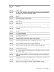
... States Intel Core 2 Duo T9550 processor (2.66-GHz, 6-MB L2 cache) Intel Core 2 Duo P8700 processor (2.53-GHz, 3-MB L2 cache) Intel Core 2 Duo T5800 processor (2.0 GHz, 2-MB L2 cache) Turion 64 RM-74 [processor (2.2 GHz, 1-MB L2 cache) Keyboard for use with bronze-colored computer models for use... in The United States Keyboard for use with bronze-colored computer models...
... States Intel Core 2 Duo T9550 processor (2.66-GHz, 6-MB L2 cache) Intel Core 2 Duo P8700 processor (2.53-GHz, 3-MB L2 cache) Intel Core 2 Duo T5800 processor (2.0 GHz, 2-MB L2 cache) Turion 64 RM-74 [processor (2.2 GHz, 1-MB L2 cache) Keyboard for use with bronze-colored computer models for use... in The United States Keyboard for use with bronze-colored computer models...

Service Guide
Page 54
...001 512231-001 512232-001 513592-001 513593-001 513599-001 Description Keyboard for use with blue-colored computer models for use in Spain Keyboard for use with blue-colored computer models for use in Switzerland Keyboard for use with blue-colored computer models for use in French ... material) for use in models with AMD processors with MediaSmart Keyboard cover for use in standard computer models Keyboard cover for use in bronze-colored computer models Core 2 Duo T6400 (2.06 GHz, 3-MB L2 cache) Core 2 Duo T6600 (2.2 GHz, 3-MB L2 cache) Pentium Dual-Core T4200 processor, 2.0-MHz, 4-MB L2 cache;
...001 512231-001 512232-001 513592-001 513593-001 513599-001 Description Keyboard for use with blue-colored computer models for use in Spain Keyboard for use with blue-colored computer models for use in Switzerland Keyboard for use with blue-colored computer models for use in French ... material) for use in models with AMD processors with MediaSmart Keyboard cover for use in standard computer models Keyboard cover for use in bronze-colored computer models Core 2 Duo T6400 (2.06 GHz, 3-MB L2 cache) Core 2 Duo T6600 (2.2 GHz, 3-MB L2 cache) Pentium Dual-Core T4200 processor, 2.0-MHz, 4-MB L2 cache;

Service Guide
Page 80
... or in blue-colored computer models Spare part number 486901-xxx 507319-001 508119-xxx 508120-xxx NOTE: For a comprehensive list of keyboard spare part numbers, see Battery on page 55). Remove the two Phillips PM2.5×17.0 screws (1), and the Phillips PM2.5×9.0... screw (2) that secure the keyboard to the computer. 3. Turn the computer display-side up, with the front toward you. 4. Remove the keyboard: 1. Before removing the keyboard, follow these steps: 1. Shut down through the operating system. 2. Remove the battery...
... or in blue-colored computer models Spare part number 486901-xxx 507319-001 508119-xxx 508120-xxx NOTE: For a comprehensive list of keyboard spare part numbers, see Battery on page 55). Remove the two Phillips PM2.5×17.0 screws (1), and the Phillips PM2.5×9.0... screw (2) that secure the keyboard to the computer. 3. Turn the computer display-side up, with the front toward you. 4. Remove the keyboard: 1. Before removing the keyboard, follow these steps: 1. Shut down through the operating system. 2. Remove the battery...
Service Guide
Page 81
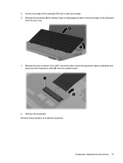
Lift the rear edge of the keyboard (1) until it back to disengage the tabs on the front edge of the keyboard from the system board. 8. Release the keyboard (2) by sliding it rests at an angle. 6. Remove the keyboard. Component replacement procedures 73 Release the zero insertion force (ZIF) connector (1) to install the keyboard. 5. Reverse this procedure to which the keyboard cable is attached and disconnect the keyboard cable (2) from the top cover. 7.
Lift the rear edge of the keyboard (1) until it back to disengage the tabs on the front edge of the keyboard from the system board. 8. Release the keyboard (2) by sliding it rests at an angle. 6. Remove the keyboard. Component replacement procedures 73 Release the zero insertion force (ZIF) connector (1) to install the keyboard. 5. Reverse this procedure to which the keyboard cable is attached and disconnect the keyboard cable (2) from the top cover. 7.
Service Guide
Page 82
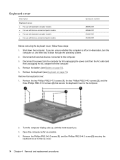
... with bronze-colored computer models Spare part number 486852-001 495663-001 512231-001 512232-001 Before removing the keyboard cover, follow these steps: 1. Remove the battery (see Keyboard on , and then shut it down the computer. Remove the two Phillips PM2.5×7.0 screws (1), the... two Phillips PM2.0×4.0 screws (2), and the three Phillips PM2.5×3.0 screws (3) that secure the keyboard cover to the computer. 3. Shut down through the operating system. 2. Remove the Phillips PM2.5×9.0 screw (1), and the Phillips PM2.5×4.0 ...
... with bronze-colored computer models Spare part number 486852-001 495663-001 512231-001 512232-001 Before removing the keyboard cover, follow these steps: 1. Remove the battery (see Keyboard on , and then shut it down the computer. Remove the two Phillips PM2.5×7.0 screws (1), the... two Phillips PM2.0×4.0 screws (2), and the three Phillips PM2.5×3.0 screws (3) that secure the keyboard cover to the computer. 3. Shut down through the operating system. 2. Remove the Phillips PM2.5×9.0 screw (1), and the Phillips PM2.5×4.0 ...
Service Guide
Page 83
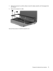
Remove the keyboard cover (4). Reverse this procedure to install the keyboard cover. Release the keyboard cover (3) by sliding it toward the display assembly until it disengages from the computer. 6. Component replacement procedures 75 5.
Remove the keyboard cover (4). Reverse this procedure to install the keyboard cover. Release the keyboard cover (3) by sliding it toward the display assembly until it disengages from the computer. 6. Component replacement procedures 75 5.
Service Guide
Page 84
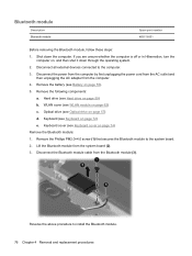
... number 483113-001 Before removing the Bluetooth module, follow these steps: 1. Remove the following components: a. Optical drive (see Keyboard on page 57) d. Keyboard (see Optical drive on page 72) e. Disconnect the Bluetooth module cable from the system board (2). 3. Disconnect all external ...battery (see WLAN module on page 55). 5. WLAN cover (see Battery on page 62) c. Shut down through the operating system. 2. Keyboard cover (see Hard drive on page 74) Remove the Bluetooth module: 1. Remove the Phillips PM2.0×4.0 screw (1) that secures the Bluetooth ...
... number 483113-001 Before removing the Bluetooth module, follow these steps: 1. Remove the following components: a. Optical drive (see Keyboard on page 57) d. Keyboard (see Optical drive on page 72) e. Disconnect the Bluetooth module cable from the system board (2). 3. Disconnect all external ...battery (see WLAN module on page 55). 5. WLAN cover (see Battery on page 62) c. Shut down through the operating system. 2. Keyboard cover (see Hard drive on page 74) Remove the Bluetooth module: 1. Remove the Phillips PM2.0×4.0 screw (1) that secures the Bluetooth ...
Service Guide
Page 85
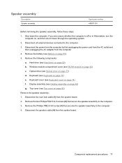
... Disconnect the num lock cable (1) from the system board. Disconnect the speaker cable (4) from the system board. 2. Optical drive (see Keyboard cover on page 57) d. Component replacement procedures 77 Shut down through the operating system. 2. Disconnect the power from the computer by first... shut it down the computer. Hard drive (see Display assembly on page 59) b. Wireless module compartment cover (see Keyboard on page 62) c. Keyboard (see WLAN module on page 72) e. Remove the Phillips PM2.5×9.0 screw (3) that secure the speaker assembly to the computer...
... Disconnect the num lock cable (1) from the system board. Disconnect the speaker cable (4) from the system board. 2. Optical drive (see Keyboard cover on page 57) d. Component replacement procedures 77 Shut down through the operating system. 2. Disconnect the power from the computer by first... shut it down the computer. Hard drive (see Display assembly on page 59) b. Wireless module compartment cover (see Keyboard on page 62) c. Keyboard (see WLAN module on page 72) e. Remove the Phillips PM2.5×9.0 screw (3) that secure the speaker assembly to the computer...
Service Guide
Page 87
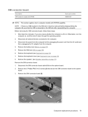
...power cord from the AC outlet and then unplugging the AC adapter from the system board. 2. Remove the keyboard cover (see SIM on page 55). 5. Remove the SIM (see Keyboard cover on page 72) 7. Remove the SIM connector board (3). Component replacement procedures 79 SIM connector board ...all external devices connected to computer models with WWAN Spare part number 486845-001 NOTE: This section applies only to the computer. 3. Remove the keyboard (see Keyboard on page 74) 8. Remove the 2 Phillips PM2.5×4.0 screws (2) that the SIM is a SIM inserted in the SIM slot after ...
...power cord from the AC outlet and then unplugging the AC adapter from the system board. 2. Remove the keyboard cover (see SIM on page 55). 5. Remove the SIM (see Keyboard cover on page 72) 7. Remove the SIM connector board (3). Component replacement procedures 79 SIM connector board ...all external devices connected to computer models with WWAN Spare part number 486845-001 NOTE: This section applies only to the computer. 3. Remove the keyboard (see Keyboard on page 74) 8. Remove the 2 Phillips PM2.5×4.0 screws (2) that the SIM is a SIM inserted in the SIM slot after ...

Service Guide
Page 90
.... 4. Disconnect the wireless antenna cables from path (2). 2. Locate the wireless antenna cable (1), and remove from the WLAN module (see Keyboard cover on page 77) Remove the display assembly: 1. CAUTION: The display assembly will be unsupported when the following components: a. Remove ...the display assembly, support it from the system board (3). 3. Speaker (see Keyboard on page 62). 6. Disconnect the wireless antenna cable from the system board (2). Remove the following screws are removed. 5. Keyboard cover (see WLAN module on page 72) b. To prevent damage to the ...
.... 4. Disconnect the wireless antenna cables from path (2). 2. Locate the wireless antenna cable (1), and remove from the WLAN module (see Keyboard cover on page 77) Remove the display assembly: 1. CAUTION: The display assembly will be unsupported when the following components: a. Remove ...the display assembly, support it from the system board (3). 3. Speaker (see Keyboard on page 62). 6. Disconnect the wireless antenna cable from the system board (2). Remove the following screws are removed. 5. Keyboard cover (see WLAN module on page 72) b. To prevent damage to the ...
Service Guide
Page 100
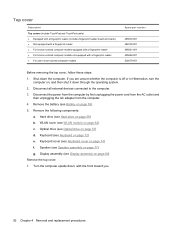
... battery (see Optical drive on page 57) d. Optical drive (see Battery on page 77) g. Keyboard (see Speaker assembly on page 55). 5. Speaker (see Keyboard on page 74) f. Display assembly (see Keyboard cover on page 72) e. Turn the computer upside down, with a fingerprint reader ● For ...use in Hibernation, turn the computer on page 80) Remove the top cover: 1. Shut down through the operating system. 2. Keyboard cover (see Display assembly on , and then shut it down the computer. Top cover Description Top covers (include TouchPad and TouchPad cable) &#...
... battery (see Optical drive on page 57) d. Optical drive (see Battery on page 77) g. Keyboard (see Speaker assembly on page 55). 5. Speaker (see Keyboard on page 74) f. Display assembly (see Keyboard cover on page 72) e. Turn the computer upside down, with a fingerprint reader ● For ...use in Hibernation, turn the computer on page 80) Remove the top cover: 1. Shut down through the operating system. 2. Keyboard cover (see Display assembly on , and then shut it down the computer. Top cover Description Top covers (include TouchPad and TouchPad cable) &#...
Service Guide
Page 103
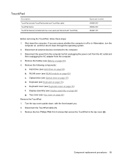
... 57) d. Hard drive (see Display assembly on page 72) e. Display assembly (see Hard drive on page 55). 5. Keyboard (see Keyboard cover on page 74) f. Turn the top cover upside down the computer. Keyboard cover (see Keyboard on page 80) g. Remove the five Phillips PM2.5×4.0 screws that secure the TouchPad to the computer. 3. Shut...
... 57) d. Hard drive (see Display assembly on page 72) e. Display assembly (see Hard drive on page 55). 5. Keyboard (see Keyboard cover on page 74) f. Turn the top cover upside down the computer. Keyboard cover (see Keyboard on page 80) g. Remove the five Phillips PM2.5×4.0 screws that secure the TouchPad to the computer. 3. Shut...
Service Guide
Page 105
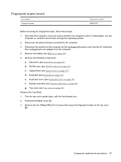
... page 74) f. Fold back the Mylar cover (1). 3. Disconnect all external devices connected to the top cover (2). Keyboard (see Keyboard cover on page 72) e. Component replacement procedures 97 Disconnect the power from the computer by first unplugging the power cord from the AC outlet and ...
... page 74) f. Fold back the Mylar cover (1). 3. Disconnect all external devices connected to the top cover (2). Keyboard (see Keyboard cover on page 72) e. Component replacement procedures 97 Disconnect the power from the computer by first unplugging the power cord from the AC outlet and ...
Service Guide
Page 107
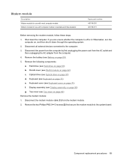
...drive (see Optical drive on page 57) d. Optical drive (see Hard drive on page 59) b. Display assembly (see Keyboard cover on page 74) f. Component replacement procedures 99 Keyboard cover (see Display assembly on page 80) g. Remove the two Phillips PM2.0×4.0 screws (2) that secure the modem module ... the modem module cable (1) from the computer. 4. Remove the battery (see Top cover on page 92) Remove the modem module: 1. Keyboard (see WLAN module on page 62) c. Modem module Description Modem module for use with most computer models Modem module for use with computer models...
...drive (see Optical drive on page 57) d. Optical drive (see Hard drive on page 59) b. Display assembly (see Keyboard cover on page 74) f. Component replacement procedures 99 Keyboard cover (see Display assembly on page 80) g. Remove the two Phillips PM2.0×4.0 screws (2) that secure the modem module ... the modem module cable (1) from the computer. 4. Remove the battery (see Top cover on page 92) Remove the modem module: 1. Keyboard (see WLAN module on page 62) c. Modem module Description Modem module for use with most computer models Modem module for use with computer models...


