Service Guide
Page 6
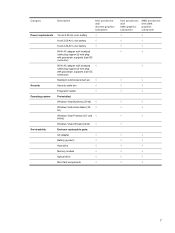
... SIM ...56 Optical drive ...57 Hard drive ...59 WLAN module ...62 WWAN module ...65 Memory module ...67 RTC battery ...69 Camera/microphone module for standard display assembly 70 Keyboard ...72 Keyboard cover ...74 Bluetooth module ...76 Speaker assembly ...77 SIM connector board ...79 Display ...
... SIM ...56 Optical drive ...57 Hard drive ...59 WLAN module ...62 WWAN module ...65 Memory module ...67 RTC battery ...69 Camera/microphone module for standard display assembly 70 Keyboard ...72 Keyboard cover ...74 Bluetooth module ...76 Speaker assembly ...77 SIM connector board ...79 Display ...
Service Guide
Page 8
Restore to a previous date and time 165 Creating recovery discs 165 Performing a recovery ...166 Recovering from the recovery discs 166 Recovering from the dedicated recovery partition (select models only 166 9 Connector pin assignments Audio-in (microphone) ...168 Audio-out (headphone) ...169 External monitor ...170 RJ-11 (modem) ...171 RJ-45 (network) ...172 HDMI ...173 Universal Serial Bus ...174 10 Power cord set requirements Requirements for all countries or regions 175 Requirements for specific countries or regions 176 11 Recycling Battery ...177 Display ...177 Index ...183 viii
Restore to a previous date and time 165 Creating recovery discs 165 Performing a recovery ...166 Recovering from the recovery discs 166 Recovering from the dedicated recovery partition (select models only 166 9 Connector pin assignments Audio-in (microphone) ...168 Audio-out (headphone) ...169 External monitor ...170 RJ-11 (modem) ...171 RJ-45 (network) ...172 HDMI ...173 Universal Serial Bus ...174 10 Power cord set requirements Requirements for all countries or regions 175 Requirements for specific countries or regions 176 11 Recycling Battery ...177 Display ...177 Index ...183 viii
Service Guide
Page 13
...; 54g 802.11b/g with Bluetooth and √ 2 antennae 2 WWAN 5-band antennae built √ into display assembly Subscriber identity module (SIM) √ security (customer-accessible in battery bay) Intel processors with UMA graphics subsystem AMD processors with UMA graphics subsystem √ √ √ √ √ √ √ √ √ √ √ √...
...; 54g 802.11b/g with Bluetooth and √ 2 antennae 2 WWAN 5-band antennae built √ into display assembly Subscriber identity module (SIM) √ security (customer-accessible in battery bay) Intel processors with UMA graphics subsystem AMD processors with UMA graphics subsystem √ √ √ √ √ √ √ √ √ √ √ √...
Service Guide
Page 15
and √ 64-bit) Windows Vista Ultimate (64-bit) √ Serviceability End-user replaceable parts: AC adapter √ Battery (system) √ Hard drive √ Memory module √ Optical drive √ Mini Card components √ Intel processors with UMA ... (32- Category Description Intel processors with discrete graphics subsystem Power requirements 12-cell 2.20-Ah Li-ion battery √ 6-cell 2.55-Ah Li-ion battery √ 6-cell 2.20-Ah Li-ion battery √ 65-W AC adapter with localized cable plug support (2-wire plug with ground pin, supports 2-pin...
and √ 64-bit) Windows Vista Ultimate (64-bit) √ Serviceability End-user replaceable parts: AC adapter √ Battery (system) √ Hard drive √ Memory module √ Optical drive √ Mini Card components √ Intel processors with UMA ... (32- Category Description Intel processors with discrete graphics subsystem Power requirements 12-cell 2.20-Ah Li-ion battery √ 6-cell 2.55-Ah Li-ion battery √ 6-cell 2.20-Ah Li-ion battery √ 65-W AC adapter with localized cable plug support (2-wire plug with ground pin, supports 2-pin...
Service Guide
Page 17
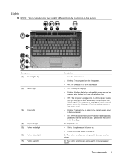
... in the Sleep state. ● Off: The computer is off . On: The volume scroll zone is being accessed. ● On: HP ProtectSmart Hard Drive Protection has temporarily parked the internal hard drive, and if present, the hard drive in this section. Component (1) Power lights... is on . ● Amber: Computer sound is turned off when all batteries in Hibernation. ● On: A battery is charging. ● Blinking: A battery that is the only available power source has reached a low battery level or a critical battery level. ● Off: If the computer is plugged into an external power...
... in the Sleep state. ● Off: The computer is off . On: The volume scroll zone is being accessed. ● On: HP ProtectSmart Hard Drive Protection has temporarily parked the internal hard drive, and if present, the hard drive in this section. Component (1) Power lights... is on . ● Amber: Computer sound is turned off when all batteries in Hibernation. ● On: A battery is charging. ● Blinking: A battery that is the only available power source has reached a low battery level or a critical battery level. ● Off: If the computer is plugged into an external power...
Service Guide
Page 23
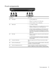
..., a headset, or television audio. Receives a signal from the HP Remote Control (select models only). If the computer is not plugged into an external power source, the light stays off until the battery reaches a low battery level. ● Blinking: The hard drive or optical drive (select..., the light is being accessed. ● On: HP ProtectSmart Hard Drive Protection has temporarily parked the internal hard drive, and if present, the hard drive in the computer are fully charged. Front components Component (1) Power light (2) Battery light (3) Drive light (4) Consumer infrared lens (5) Audio...
..., a headset, or television audio. Receives a signal from the HP Remote Control (select models only). If the computer is not plugged into an external power source, the light stays off until the battery reaches a low battery level. ● Blinking: The hard drive or optical drive (select..., the light is being accessed. ● On: HP ProtectSmart Hard Drive Protection has temporarily parked the internal hard drive, and if present, the hard drive in the computer are fully charged. Front components Component (1) Power light (2) Battery light (3) Drive light (4) Consumer infrared lens (5) Audio...
Service Guide
Page 26
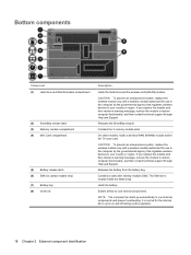
... select models, holds a wireless WAN (WWAN) module and/or the TV tuner card. It is located inside the battery bay. The SIM slot is normal for the internal fan to cool internal components. If you replace the module and .... Bottom components Component (1) Hard drive and WLAN module compartment (2) SmartBay release latch (3) Memory module compartment (4) Mini Card compartment (5) Battery release latch (6) SIM slot (select models only) (7) Battery bay (8) Vents (4) Description Holds the hard drive and the wireless LAN (WLAN) module. Releases the SmartBay module. Contains a subscriber...
... select models, holds a wireless WAN (WWAN) module and/or the TV tuner card. It is located inside the battery bay. The SIM slot is normal for the internal fan to cool internal components. If you replace the module and .... Bottom components Component (1) Hard drive and WLAN module compartment (2) SmartBay release latch (3) Memory module compartment (4) Mini Card compartment (5) Battery release latch (6) SIM slot (select models only) (7) Battery bay (8) Vents (4) Description Holds the hard drive and the wireless LAN (WLAN) module. Releases the SmartBay module. Contains a subscriber...
Service Guide
Page 31
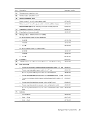
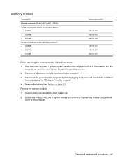
...For use in computer models with Intel processors: ● 2048-MB ● 1024-MB ● 512-MB 482169-001 482168-001 482167-001 RTC battery 486835-001 Audio board (includes audio connectors, infrared lens, and audio board cable) 486840-001 Base enclosures ● For use only in standard computer ... computer models with a modem module 495666-001 ● For use only in bronze-colored computer models with a modem module and TV 495667-001 tuner Batteries ● 12-cell, 8.80-Ah ● 6-cell, 2.55-Ah ● 6-cell, 2.20-Ah 484172-001 484171-001 482186-003 Computer major components...
...For use in computer models with Intel processors: ● 2048-MB ● 1024-MB ● 512-MB 482169-001 482168-001 482167-001 RTC battery 486835-001 Audio board (includes audio connectors, infrared lens, and audio board cable) 486840-001 Base enclosures ● For use only in standard computer ... computer models with a modem module 495666-001 ● For use only in bronze-colored computer models with a modem module and TV 495667-001 tuner Batteries ● 12-cell, 8.80-Ah ● 6-cell, 2.55-Ah ● 6-cell, 2.20-Ah 484172-001 484171-001 482186-003 Computer major components...
Service Guide
Page 46
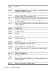
... processor (2.53-GHz, 6-MB L2 cache) 14.1-inch, WXGA, BrightView display panel for use in computers with Intel processors (includes display panel cable) 14.1-inch, WXGA, BrightView LED display panel for use in computers with Intel processors (includes display panel cable) HP un2400 Mobile Broadband Module 6-cell battery, 2.55-Ah 12-cell battery, 8.80...
... processor (2.53-GHz, 6-MB L2 cache) 14.1-inch, WXGA, BrightView display panel for use in computers with Intel processors (includes display panel cable) 14.1-inch, WXGA, BrightView LED display panel for use in computers with Intel processors (includes display panel cable) HP un2400 Mobile Broadband Module 6-cell battery, 2.55-Ah 12-cell battery, 8.80...
Service Guide
Page 47
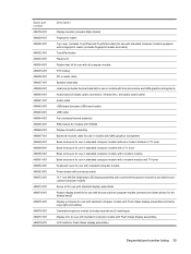
... computer models equipped with a fingerprint reader (includes fingerprint reader and cable) TouchPad button Plastics kit Rubber feet kit for use with all computer models RTC battery DC-in audio cable Speaker assembly Heat sink (includes thermal material) for use in models with Intel processors and UMA graphics subsystems Audio board (includes...
... computer models equipped with a fingerprint reader (includes fingerprint reader and cable) TouchPad button Plastics kit Rubber feet kit for use with all computer models RTC battery DC-in audio cable Speaker assembly Heat sink (includes thermal material) for use in models with Intel processors and UMA graphics subsystems Audio board (includes...
Service Guide
Page 60
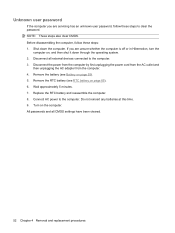
... then shut it down the computer. All passwords and all external devices connected to the computer. Remove the battery (see RTC battery on page 55). 5. Disconnect all CMOS settings have been cleared. 52 Chapter 4 Removal and replacement procedures Remove the RTC... battery (see Battery on page 69). 6. Do not reinsert any batteries at this time. 9. NOTE: These steps also clear CMOS. Wait approximately 5 minutes. 7. Shut down through the operating ...
... then shut it down the computer. All passwords and all external devices connected to the computer. Remove the battery (see RTC battery on page 55). 5. Disconnect all CMOS settings have been cleared. 52 Chapter 4 Removal and replacement procedures Remove the RTC... battery (see Battery on page 69). 6. Do not reinsert any batteries at this time. 9. NOTE: These steps also clear CMOS. Wait approximately 5 minutes. 7. Shut down through the operating ...
Service Guide
Page 63
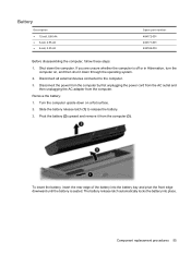
...from the computer. To insert the battery, insert the rear edge of the battery into place. Shut down through the operating system. 2. Pivot the battery (2) upward and remove it down the computer. The battery release latch automatically locks the battery into the battery bay and pivot the front edge...484172-001 484171-001 482186-003 Before disassembling the computer, follow these steps: 1. Disconnect all external devices connected to release the battery. 3. Disconnect the power from the computer by first unplugging the power cord from the AC outlet and then unplugging the AC ...
...from the computer. To insert the battery, insert the rear edge of the battery into place. Shut down through the operating system. 2. Pivot the battery (2) upward and remove it down the computer. The battery release latch automatically locks the battery into the battery bay and pivot the front edge...484172-001 484171-001 482186-003 Before disassembling the computer, follow these steps: 1. Disconnect all external devices connected to release the battery. 3. Disconnect the power from the computer by first unplugging the power cord from the AC outlet and then unplugging the AC ...
Service Guide
Page 64
Before removing the SIM, follow these steps: 1. Reverse this procedure to the computer. 3. Remove the SIM: 1. Remove the battery (see Battery on the SIM (1). (The module is a SIM inserted in the SIM slot after reassembling the computer. Remove the SIM (2) from the computer. 4. Shut down through ...
Before removing the SIM, follow these steps: 1. Reverse this procedure to the computer. 3. Remove the SIM: 1. Remove the battery (see Battery on the SIM (1). (The module is a SIM inserted in the SIM slot after reassembling the computer. Remove the SIM (2) from the computer. 4. Shut down through ...
Service Guide
Page 66
... the power from the computer by first unplugging the power cord from the AC outlet and then unplugging the AC adapter from the battery bay. 3. If it down the computer. If you . 2. Remove the battery (see Battery on , and then shut it is off or in Hibernation, turn the computer on page 55).
... the power from the computer by first unplugging the power cord from the AC outlet and then unplugging the AC adapter from the battery bay. 3. If it down the computer. If you . 2. Remove the battery (see Battery on , and then shut it is off or in Hibernation, turn the computer on page 55).
Service Guide
Page 68
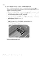
... 486833-001. 4. Remove the three black Phillips PM2.0×4.0 screws (1) that secure the hard drive bay cover to the computer. 5. If you . 2. Remove the battery (see Battery on , and then shut it to right, and remove the cover (3). Loosen the two Phillips PM2.5×6.0 captive screws (1) that secure the hard drive to...
... 486833-001. 4. Remove the three black Phillips PM2.0×4.0 screws (1) that secure the hard drive bay cover to the computer. 5. If you . 2. Remove the battery (see Battery on , and then shut it to right, and remove the cover (3). Loosen the two Phillips PM2.5×6.0 captive screws (1) that secure the hard drive to...
Service Guide
Page 72
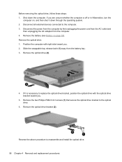
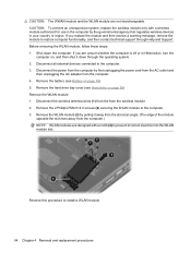
...Remove the 2 Phillips PM2.0×4.0 screws (2) securing the WLAN module to the computer. 3. Remove the hard drive bay cover (see Battery on page 59) Remove the WLAN module: 1. Disconnect all external devices connected to the computer. 3. CAUTION: To prevent an unresponsive system,... replace the wireless module only with a notch (4) to prevent incorrect insertion into the WLAN module slot. Remove the battery (see Hard drive on page 55). 5. Disconnect the wireless antenna wires (1) from the from the computer. 4. Disconnect the power from ...
...Remove the 2 Phillips PM2.0×4.0 screws (2) securing the WLAN module to the computer. 3. Remove the hard drive bay cover (see Battery on page 59) Remove the WLAN module: 1. Disconnect all external devices connected to the computer. 3. CAUTION: To prevent an unresponsive system,... replace the wireless module only with a notch (4) to prevent incorrect insertion into the WLAN module slot. Remove the battery (see Hard drive on page 55). 5. Disconnect the wireless antenna wires (1) from the from the computer. 4. Disconnect the power from ...
Service Guide
Page 73
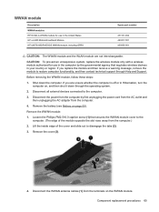
... out to the computer. 3. Loosen the Phillips PM2.5×6.0 captive screw (1) that regulates wireless devices in the United States HP un2400 Mobile Broadband Module HP UMTS/HSDPA/EDGE WWAN module, including GPRS Spare part number 451131-002 483377-001 459350-001 CAUTION: The WWAN module and ... off or in Hibernation, turn the computer on the WWAN module. Component replacement procedures 65 Shut down through Help and Support. Remove the battery (see Battery on page 55). Disconnect the power from the terminals on , and then shut it down the computer. Remove the WWAN module: 1....
... out to the computer. 3. Loosen the Phillips PM2.5×6.0 captive screw (1) that regulates wireless devices in the United States HP un2400 Mobile Broadband Module HP UMTS/HSDPA/EDGE WWAN module, including GPRS Spare part number 451131-002 483377-001 459350-001 CAUTION: The WWAN module and ... off or in Hibernation, turn the computer on the WWAN module. Component replacement procedures 65 Shut down through Help and Support. Remove the battery (see Battery on page 55). Disconnect the power from the terminals on , and then shut it down the computer. Remove the WWAN module: 1....
Service Guide
Page 75
... power from the computer by first unplugging the power cord from the AC outlet and then unplugging the AC adapter from the computer. 4. Remove the battery (see Battery on , and then shut it down the computer. Shut down through the operating system. 2. Loosen the Phillips PM2.5×6.0 captive screw (1) that secures the...
... power from the computer by first unplugging the power cord from the AC outlet and then unplugging the AC adapter from the computer. 4. Remove the battery (see Battery on , and then shut it down the computer. Shut down through the operating system. 2. Loosen the Phillips PM2.5×6.0 captive screw (1) that secures the...
Service Guide
Page 77
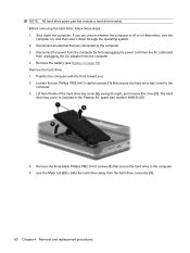
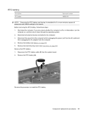
... computer is off or in Hibernation, turn the computer on page 59). Disconnect all passwords and CMOS settings to be cleared. Remove the RTC battery: 1. Component replacement procedures 69 Disconnect the power from the computer by first unplugging the power cord from the AC outlet and then unplugging the ...AC adapter from the system board. 2. Reverse this procedure to the computer. 3. Remove the battery (see Hard drive on , and then shut it uninstalled for 5 or more minutes causes all external devices connected to install the RTC...
... computer is off or in Hibernation, turn the computer on page 59). Disconnect all passwords and CMOS settings to be cleared. Remove the RTC battery: 1. Component replacement procedures 69 Disconnect the power from the computer by first unplugging the power cord from the AC outlet and then unplugging the ...AC adapter from the system board. 2. Reverse this procedure to the computer. 3. Remove the battery (see Hard drive on , and then shut it uninstalled for 5 or more minutes causes all external devices connected to install the RTC...
Service Guide
Page 78
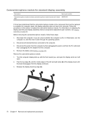
... not have to the computer. 3. For information on replacing the display assembly and display assembly internal components replacement part numbers, see Battery on page 80. Before removing the camera/microphone module, follow these steps: 1. Remove the camera/microphone module: 1. Release the display...edges of the left and right sides (2) of the display bezel until the bezel disengages from the computer. 4. Remove the battery (see Display assembly on page 55). Camera/microphone module for standard display assembly Description Spare part number Camera/microphone module (includes...
... not have to the computer. 3. For information on replacing the display assembly and display assembly internal components replacement part numbers, see Battery on page 80. Before removing the camera/microphone module, follow these steps: 1. Remove the camera/microphone module: 1. Release the display...edges of the left and right sides (2) of the display bezel until the bezel disengages from the computer. 4. Remove the battery (see Display assembly on page 55). Camera/microphone module for standard display assembly Description Spare part number Camera/microphone module (includes...


