Getting Started Guide
Page 12
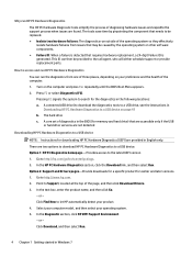
...Go. - or - Click Find Now to a USB device NOTE: Instructions for memory and hard drive) that are accessible only if the USB or hard drive versions are not detected Downloading HP PC Hardware Diagnostics to let HP automatically detect your operating system. 5. Click Download, and then select Run. 4 ...Select your computer model, and then select your product. 4. The tools save time by pinpointing the component that needs to access and run HP PC Hardware Diagnostics You can then be caused by the operating system or other software components. ● Failure ID: When a failure is...
...Go. - or - Click Find Now to a USB device NOTE: Instructions for memory and hard drive) that are accessible only if the USB or hard drive versions are not detected Downloading HP PC Hardware Diagnostics to let HP automatically detect your operating system. 5. Click Download, and then select Run. 4 ...Select your computer model, and then select your product. 4. The tools save time by pinpointing the component that needs to access and run HP PC Hardware Diagnostics You can then be caused by the operating system or other software components. ● Failure ID: When a failure is...

Getting Started Guide
Page 24
... problems with the computer, try the appropriate solutions as described in the previous sections and summarized below to try to the system board. In the HP PC Hardware Diagnostics section, click the Download link, and then select Run. Option 2: Support and Drivers pages-Provide downloads for a specific product for the diagnostics..., be sure to disconnect the power cord from one of three places, depending on your preference and the health of diagnostics in the BIOS (for memory and hard drive) that are accessible only if the USB or hard drive versions are provided in Downloading...
... problems with the computer, try the appropriate solutions as described in the previous sections and summarized below to try to the system board. In the HP PC Hardware Diagnostics section, click the Download link, and then select Run. Option 2: Support and Drivers pages-Provide downloads for a specific product for the diagnostics..., be sure to disconnect the power cord from one of three places, depending on your preference and the health of diagnostics in the BIOS (for memory and hard drive) that are accessible only if the USB or hard drive versions are provided in Downloading...

Getting Started Guide
Page 33
.... A connected USB drive (to download the diagnostics tools to a USB drive, see the instructions in the follow sequence: a. Go to search for memory and hard drive) that requires hardware replacement, a 24-digit Failure ID is generated. Turn on the computer and press Esc repeatedly until the BIOS Boot...You can then be provided to the latest UEFI version 1. Go to a USB device NOTE: Instructions for earlier and later versions 1. Point to let HP automatically detect your operating system. 5. In the text box, enter the product name, and then click Go. - If you encounter issues 25 Why...
.... A connected USB drive (to download the diagnostics tools to a USB drive, see the instructions in the follow sequence: a. Go to search for memory and hard drive) that requires hardware replacement, a 24-digit Failure ID is generated. Turn on the computer and press Esc repeatedly until the BIOS Boot...You can then be provided to the latest UEFI version 1. Go to a USB device NOTE: Instructions for earlier and later versions 1. Point to let HP automatically detect your operating system. 5. In the text box, enter the product name, and then click Go. - If you encounter issues 25 Why...

Getting Started Guide
Page 40
...then select User Guides. From the Start screen type support, and then select the HP Support Assistant app. 2. Type support in the taskbar search box, and then select the HP Support Assistant app. 2. also includes basic troubleshooting information should you encounter any problems ...; Accessing user guides (Windows 7 systems) ▲ Click Start > All Programs > HP Help and Support > HP Documentation. Select My PC, and then select User Guides. includes information on RTC batteries, memory, and power supply. ● Maintenance and Service Guide (English only)-Provides information on ...
...then select User Guides. From the Start screen type support, and then select the HP Support Assistant app. 2. Type support in the taskbar search box, and then select the HP Support Assistant app. 2. also includes basic troubleshooting information should you encounter any problems ...; Accessing user guides (Windows 7 systems) ▲ Click Start > All Programs > HP Help and Support > HP Documentation. Select My PC, and then select User Guides. includes information on RTC batteries, memory, and power supply. ● Maintenance and Service Guide (English only)-Provides information on ...

Hardware Reference Guide
Page 5
... Replacing the computer access panel ...7 Removing the front bezel ...8 Removing bezel blanks ...9 Replacing the front bezel ...9 System board connections ...10 Installing additional memory ...11 DIMMs ...11 DDR4-SDRAM DIMMs ...11 Populating DIMM sockets ...11 Installing DIMMs ...12 Removing or installing an expansion card ...14 Drive positions ...18...inch or 2.5-inch hard drive 28 Installing a 3.5-inch or 2.5-inch hard drive 29 Installing a security lock ...34 Cable lock ...34 Padlock ...34 HP Business PC Security Lock V2 ...35 Front bezel security ...40 Appendix A Battery replacement ...42 v
... Replacing the computer access panel ...7 Removing the front bezel ...8 Removing bezel blanks ...9 Replacing the front bezel ...9 System board connections ...10 Installing additional memory ...11 DIMMs ...11 DDR4-SDRAM DIMMs ...11 Populating DIMM sockets ...11 Installing DIMMs ...12 Removing or installing an expansion card ...14 Drive positions ...18...inch or 2.5-inch hard drive 28 Installing a 3.5-inch or 2.5-inch hard drive 29 Installing a security lock ...34 Cable lock ...34 Padlock ...34 HP Business PC Security Lock V2 ...35 Front bezel security ...40 Appendix A Battery replacement ...42 v

Hardware Reference Guide
Page 16
... Card black black black black black white black white black light blue dark blue Expansion Card Expansion Card Expansion Card Optional Second Serial Port Battery Memory Module Memory Module Memory Module Memory Module Any SATA Device other than the Primary Hard Drive Primary Hard Drive 10 Chapter 2 Hardware upgrades
... Card black black black black black white black white black light blue dark blue Expansion Card Expansion Card Expansion Card Optional Second Serial Port Battery Memory Module Memory Module Memory Module Memory Module Any SATA Device other than the Primary Hard Drive Primary Hard Drive 10 Chapter 2 Hardware upgrades

Hardware Reference Guide
Page 17
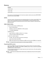
...timing) ● contain the mandatory JEDEC SPD information In addition, the computer supports: ● 512-Mbit, 1-Gbit, and 2-Gbit non-ECC memory technologies ● single-sided and double-sided DIMMs ● DIMMs constructed with x8 and x16 DDR devices; The sockets are populated with up to... mode, dual channel mode, or flex mode, depending on the system board, with double data rate 4 synchronous dynamic random access memory (DDR4-SDRAM) dual inline memory modules (DIMMs). DIMMs constructed with x4 SDRAM are not supported NOTE: The system will not operate properly if you can be :...
...timing) ● contain the mandatory JEDEC SPD information In addition, the computer supports: ● 512-Mbit, 1-Gbit, and 2-Gbit non-ECC memory technologies ● single-sided and double-sided DIMMs ● DIMMs constructed with x8 and x16 DDR devices; The sockets are populated with up to... mode, dual channel mode, or flex mode, depending on the system board, with double data rate 4 synchronous dynamic random access memory (DDR4-SDRAM) dual inline memory modules (DIMMs). DIMMs constructed with x4 SDRAM are not supported NOTE: The system will not operate properly if you can be :...

Hardware Reference Guide
Page 18
...disengage any external devices. Disconnect the power cord from the computer. 3. Regardless of the power-on state, voltage is always supplied to the memory modules as long as compact discs or USB flash drives, from the power outlet and disconnect any security devices that prohibit opening the computer. ...must disconnect the power cord and wait approximately 30 seconds for the power to Electrostatic discharge on state, voltage is always supplied to the memory modules as long as single channel. ● In any mode, the maximum operational speed is not equal to prevent corrosion and/or ...
...disengage any external devices. Disconnect the power cord from the computer. 3. Regardless of the power-on state, voltage is always supplied to the memory modules as long as compact discs or USB flash drives, from the power outlet and disconnect any security devices that prohibit opening the computer. ...must disconnect the power cord and wait approximately 30 seconds for the power to Electrostatic discharge on state, voltage is always supplied to the memory modules as long as single channel. ● In any mode, the maximum operational speed is not equal to prevent corrosion and/or ...

Hardware Reference Guide
Page 19
...7. Push the module down into the socket (2). Make sure the latches are in only one way. Lock any security devices that the memory capacity is fully inserted and properly seated. Repeat steps 6 and 7 to Populating DIMM sockets on the computer. NOTE...: A memory module can be installed in the closed position (3). 8. The computer should automatically recognize the additional memory the next time you turn on the memory socket. Match the notch on the module with the tab on the computer. 11...
...7. Push the module down into the socket (2). Make sure the latches are in only one way. Lock any security devices that the memory capacity is fully inserted and properly seated. Repeat steps 6 and 7 to Populating DIMM sockets on the computer. NOTE...: A memory module can be installed in the closed position (3). 8. The computer should automatically recognize the additional memory the next time you turn on the memory socket. Match the notch on the module with the tab on the computer. 11...

Hardware Reference Guide
Page 55
...29 5.25-inch optical drive 21 battery 42 computer access panel 7 drive cables 19 expansion card 14 memory 11 slim optical drive 25 L locks cable lock 34 front bezel 40 HP Business PC Security Lock 35 padlock 34 bezel blank 9 computer access panel 6 expansion card 14 front... bezel 8 slim optical drive 24 S security cable lock 34 front bezel 40 HP Business PC Security Lock 35 padlock 34 serial number location 4 shipping preparation 47 specifications memory 11 system board connections 10 M memory installation 11 socket population 11 specifications 11 V ventilation guidelines 46 O optical drive ...
...29 5.25-inch optical drive 21 battery 42 computer access panel 7 drive cables 19 expansion card 14 memory 11 slim optical drive 25 L locks cable lock 34 front bezel 40 HP Business PC Security Lock 35 padlock 34 bezel blank 9 computer access panel 6 expansion card 14 front... bezel 8 slim optical drive 24 S security cable lock 34 front bezel 40 HP Business PC Security Lock 35 padlock 34 serial number location 4 shipping preparation 47 specifications memory 11 system board connections 10 M memory installation 11 socket population 11 specifications 11 V ventilation guidelines 46 O optical drive ...

Maintenance and Service Guide
Page 6
... and replacement procedures - Microtower (MT) chassis 18 Preparation for disassembly ...18 Access panel ...19 Front bezel ...20 Front bezel security ...21 Removing bezel blanks ...22 Memory ...23 DIMMs ...23 DDR4-SDRAM DIMMs ...23 Populating DIMM sockets ...23 Installing DIMMs ...24 Expansion cards ...26 WLAN module ...30 Drives ...32 Drive positions ...34...
... and replacement procedures - Microtower (MT) chassis 18 Preparation for disassembly ...18 Access panel ...19 Front bezel ...20 Front bezel security ...21 Removing bezel blanks ...22 Memory ...23 DIMMs ...23 DDR4-SDRAM DIMMs ...23 Populating DIMM sockets ...23 Installing DIMMs ...24 Expansion cards ...26 WLAN module ...30 Drives ...32 Drive positions ...34...

Maintenance and Service Guide
Page 7
...audio problems ...93 Solving printer problems ...95 Solving keyboard and mouse problems ...96 Solving Hardware Installation Problems ...98 Solving Network Problems ...99 Solving memory problems ...102 Solving CD-ROM and DVD problems ...103 Solving USB flash drive problems ...106 Solving front panel component problems ...107 Solving Internet ... codes 115 8 Password security and resetting CMOS ...117 Resetting the password jumper ...117 Clearing and resetting the BIOS ...119 9 Using HP PC Hardware Diagnostics (UEFI) ...120 Downloading HP PC Hardware Diagnostics (UEFI) to a USB device 120 vii
...audio problems ...93 Solving printer problems ...95 Solving keyboard and mouse problems ...96 Solving Hardware Installation Problems ...98 Solving Network Problems ...99 Solving memory problems ...102 Solving CD-ROM and DVD problems ...103 Solving USB flash drive problems ...106 Solving front panel component problems ...107 Solving Internet ... codes 115 8 Password security and resetting CMOS ...117 Resetting the password jumper ...117 Clearing and resetting the BIOS ...119 9 Using HP PC Hardware Diagnostics (UEFI) ...120 Downloading HP PC Hardware Diagnostics (UEFI) to a USB device 120 vii

Maintenance and Service Guide
Page 16
Item (1) (2) (3) (4) (5) (6) * Description Access panel Front bezel System board (includes replacement thermal material) Extension board Power supply 400W, 92% efficient 280W, 92% efficient 280W, 85% efficient 280W, standard Memory modules (PC4-17000, 2133-MHz) 16-GB 8-GB 4-GB Processors (include replacement thermal material; not illustrated)) Intel Core i7-6700 processor Intel Core i5-6600 processor Intel Core i5-6500 processor 6 Chapter 2 Illustrated parts catalog
Item (1) (2) (3) (4) (5) (6) * Description Access panel Front bezel System board (includes replacement thermal material) Extension board Power supply 400W, 92% efficient 280W, 92% efficient 280W, 85% efficient 280W, standard Memory modules (PC4-17000, 2133-MHz) 16-GB 8-GB 4-GB Processors (include replacement thermal material; not illustrated)) Intel Core i7-6700 processor Intel Core i5-6600 processor Intel Core i5-6500 processor 6 Chapter 2 Illustrated parts catalog

Maintenance and Service Guide
Page 27
... from being cut or crimped when the parts are not designed to take excessive pressure on them. ● Keep cables clear of expansion cards or memory modules. A sharp bend can break the internal wires. ● Never bend a SATA data cable tighter than a 30 mm (1.18 in) radius. ● Never crease a SATA...
... from being cut or crimped when the parts are not designed to take excessive pressure on them. ● Keep cables clear of expansion cards or memory modules. A sharp bend can break the internal wires. ● Never bend a SATA data cable tighter than a 30 mm (1.18 in) radius. ● Never crease a SATA...
Maintenance and Service Guide
Page 33
... PC4-17000 The computer comes with x8 and x16 DDR devices; Sockets DIMM3 and DIMM4 operate in memory channel B. Sockets DIMM1 and DIMM2 operate in memory channel A. DIMMs The memory sockets on the system board, with at least one preinstalled DIMM. The sockets are populated with two... inferior graphics performance. DIMMs constructed with up to four industry-standard DIMMs. These memory sockets are labeled DIMM1, DIMM2, DIMM3, and DIMM4. NOTE: Single channel and unbalanced dual channel memory configurations will not operate properly if you can populate the system board with up...
... PC4-17000 The computer comes with x8 and x16 DDR devices; Sockets DIMM3 and DIMM4 operate in memory channel B. Sockets DIMM1 and DIMM2 operate in memory channel A. DIMMs The memory sockets on the system board, with at least one preinstalled DIMM. The sockets are populated with two... inferior graphics performance. DIMMs constructed with up to four industry-standard DIMMs. These memory sockets are labeled DIMM1, DIMM2, DIMM3, and DIMM4. NOTE: Single channel and unbalanced dual channel memory configurations will not operate properly if you can populate the system board with up...

Maintenance and Service Guide
Page 34
...DIMMs. With this configuration, 4-GB will run as dual channel and 1-GB will run as the computer is not equal to the total memory capacity of the computer or optional cards. For example, if you are discharged of the DIMMs in Channel A is assigned to prevent corrosion ...For optimal speed, the channels should be assigned to touch any mode, the maximum operational speed is spread between the channels. The memory module sockets have more memory than the other, the larger amount should be careful not to Channel A. Before beginning these procedures, ensure that the largest amount of...
...DIMMs. With this configuration, 4-GB will run as dual channel and 1-GB will run as the computer is not equal to the total memory capacity of the computer or optional cards. For example, if you are discharged of the DIMMs in Channel A is assigned to prevent corrosion ...For optimal speed, the channels should be assigned to touch any mode, the maximum operational speed is spread between the channels. The memory module sockets have more memory than the other, the larger amount should be careful not to Channel A. Before beginning these procedures, ensure that the largest amount of...

Maintenance and Service Guide
Page 35
3. Populate the black DIMM sockets before the white DIMM sockets. Lock any additional modules. 6. NOTE: A memory module can be installed in the closed position (3). 5. Make sure the latches are in only one way. Replace the computer access panel. 7. Reconnect ... next time you turn on the computer. Open both latches of the memory module socket (1), and insert the memory module into the socket, ensuring that the memory capacity is fully inserted and properly seated. Memory 25 Push the module down into the socket (2). For maximum performance, populate the sockets so that the ...
3. Populate the black DIMM sockets before the white DIMM sockets. Lock any additional modules. 6. NOTE: A memory module can be installed in the closed position (3). 5. Make sure the latches are in only one way. Replace the computer access panel. 7. Reconnect ... next time you turn on the computer. Open both latches of the memory module socket (1), and insert the memory module into the socket, ensuring that the memory capacity is fully inserted and properly seated. Memory 25 Push the module down into the socket (2). For maximum performance, populate the sockets so that the ...

Maintenance and Service Guide
Page 45
... black black black black black white black white black light blue dark blue Expansion Card Expansion Card Expansion Card Optional Second Serial Port Battery Memory Module Memory Module Memory Module Memory Module Any SATA Device other than the Primary Hard Drive Primary Hard Drive Drives 35 System Board Connector 1 System Board PCI Extender Connectors...
... black black black black black white black white black light blue dark blue Expansion Card Expansion Card Expansion Card Optional Second Serial Port Battery Memory Module Memory Module Memory Module Memory Module Any SATA Device other than the Primary Hard Drive Primary Hard Drive Drives 35 System Board Connector 1 System Board PCI Extender Connectors...

Maintenance and Service Guide
Page 72
... - When replacing the system board, make sure the following components are removed from the defective system board and installed on the replacement system board: ● Memory modules (Memory on page 23) ● Expansion cards (Expansion cards on page 26) ● Heat sink (Fan sink on page 53). ● Processor (Processor on page...
... - When replacing the system board, make sure the following components are removed from the defective system board and installed on the replacement system board: ● Memory modules (Memory on page 23) ● Expansion cards (Expansion cards on page 26) ● Heat sink (Fan sink on page 53). ● Processor (Processor on page...

Maintenance and Service Guide
Page 75
XU1 CPUFAN DIMM4 DIMM3 DIMM2 DIMM1 PB/LED PWRCMD SATAPWR0 Black Processor White White Processor fan Memory module Black White Black Black White Black Memory module Memory module Memory module Front I/O/power switch Power supply Drives SATA1 FRONT USB SATA2 PSWD CMOS BAT HSENSE THUNDERBOLT FRONT AUD Light blue Any SATA Device other than ...
XU1 CPUFAN DIMM4 DIMM3 DIMM2 DIMM1 PB/LED PWRCMD SATAPWR0 Black Processor White White Processor fan Memory module Black White Black Black White Black Memory module Memory module Memory module Front I/O/power switch Power supply Drives SATA1 FRONT USB SATA2 PSWD CMOS BAT HSENSE THUNDERBOLT FRONT AUD Light blue Any SATA Device other than ...


