Maintenance and Service Guide
Page 7
... Graphics ...2 Display panel ...2 Memory ...3 Memory ...4 Hard drive - HP ZBook 15u G2 Mobile Workstation 6 Audio and video ...7 Ethernet ...7 Wireless ...8 External media cards ...9 Ports ...10 Keyboard/pointing devices ...10 Power requirements ...11 Security ...11 Operating system ...12 Operating system ...13 Serviceability ...14 2 Getting to know your computer ...15 Display ...16 Buttons, speakers, and fingerprint reader (select models only 17 Keys ...18 Lights ...19 TouchPad ...20 Front ...21 Left ...22 Right ...23 ENWW vii HP EliteBook 850 G2 and HP EliteBook 750 G2 Notebook PC...
... Graphics ...2 Display panel ...2 Memory ...3 Memory ...4 Hard drive - HP ZBook 15u G2 Mobile Workstation 6 Audio and video ...7 Ethernet ...7 Wireless ...8 External media cards ...9 Ports ...10 Keyboard/pointing devices ...10 Power requirements ...11 Security ...11 Operating system ...12 Operating system ...13 Serviceability ...14 2 Getting to know your computer ...15 Display ...16 Buttons, speakers, and fingerprint reader (select models only 17 Keys ...18 Lights ...19 TouchPad ...20 Front ...21 Left ...22 Right ...23 ENWW vii HP EliteBook 850 G2 and HP EliteBook 750 G2 Notebook PC...

Maintenance and Service Guide
Page 9
... Setting a new boot order in Computer Setup 105 Dynamically choosing a boot device using the f9 prompt 106 Setting a MultiBoot Express prompt 106 Entering MultiBoot Express preferences 107 Using HP PC Hardware Diagnostics (UEFI) ...107 Downloading HP PC Hardware Diagnostics (UEFI) to a USB device 107 Using HP Sure Start (select models only 108 8 Specifications ...109 Computer specifications ...109 9 Backup and recovery ...111 Backing up your information ...111 Performing a system recovery ...111 Using the Windows recovery tools 112 Using f11 recovery tools ...112 Using Windows operating...
... Setting a new boot order in Computer Setup 105 Dynamically choosing a boot device using the f9 prompt 106 Setting a MultiBoot Express prompt 106 Entering MultiBoot Express preferences 107 Using HP PC Hardware Diagnostics (UEFI) ...107 Downloading HP PC Hardware Diagnostics (UEFI) to a USB device 107 Using HP Sure Start (select models only 108 8 Specifications ...109 Computer specifications ...109 9 Backup and recovery ...111 Backing up your information ...111 Performing a system recovery ...111 Using the Windows recovery tools 112 Using f11 recovery tools ...112 Using Windows operating...

Maintenance and Service Guide
Page 31
... 90 percent. ● Blinking amber: A battery that uses the least amount of power. Front 21 Functions like the right button on an external mouse. NOTE: On some models, the wireless light is amber when all wireless devices are off or in the Sleep state, a powersaving state. Item (1) Component Wireless light (2) Power light (3) AC adapter/Battery light (4) Hard drive light ENWW Description On: An integrated wireless device, such as a wireless local area network (WLAN) device and/or a Bluetooth device, is off . ●...
... 90 percent. ● Blinking amber: A battery that uses the least amount of power. Front 21 Functions like the right button on an external mouse. NOTE: On some models, the wireless light is amber when all wireless devices are off or in the Sleep state, a powersaving state. Item (1) Component Wireless light (2) Power light (3) AC adapter/Battery light (4) Hard drive light ENWW Description On: An integrated wireless device, such as a wireless local area network (WLAN) device and/or a Bluetooth device, is off . ●...

Maintenance and Service Guide
Page 32
...scanner or USB hub. Connects an optional USB device, such as a keyboard, mouse, external drive, printer, scanner or USB hub. Left Item (1) Component Security cable slot (2) Vents (3) External monitor port (4) USB 3.0 charging (powered) port (5) USB 3.0 port (6) Smart card reader Description Attaches an optional security cable to know your computer ENWW Supports optional smart cards. 22 Chapter 2 Getting to the computer. NOTE: The computer fan starts up automatically to use a powered port. Some USB devices require power and require you to cool internal components and...
...scanner or USB hub. Connects an optional USB device, such as a keyboard, mouse, external drive, printer, scanner or USB hub. Left Item (1) Component Security cable slot (2) Vents (3) External monitor port (4) USB 3.0 charging (powered) port (5) USB 3.0 port (6) Smart card reader Description Attaches an optional security cable to know your computer ENWW Supports optional smart cards. 22 Chapter 2 Getting to the computer. NOTE: The computer fan starts up automatically to use a powered port. Some USB devices require power and require you to cool internal components and...

Maintenance and Service Guide
Page 34
... the Start screen, select the HP Support Assistant app. To access HP Support Assistant, from the illustration in your computer Description Provides access to the hard drive bay, the wireless LAN (WLAN) module slot, the WWAN module slot, and the memory module slots. It is located inside the battery bay. CAUTION: To prevent an unresponsive system, replace the wireless module only with a wireless module authorized for the internal fan to restore computer functionality, and then contact support through HP Support Assistant. Item (1) Component Service cover (2) Service cover...
... the Start screen, select the HP Support Assistant app. To access HP Support Assistant, from the illustration in your computer Description Provides access to the hard drive bay, the wireless LAN (WLAN) module slot, the WWAN module slot, and the memory module slots. It is located inside the battery bay. CAUTION: To prevent an unresponsive system, replace the wireless module only with a wireless module authorized for the internal fan to restore computer functionality, and then contact support through HP Support Assistant. Item (1) Component Service cover (2) Service cover...
Maintenance and Service Guide
Page 57
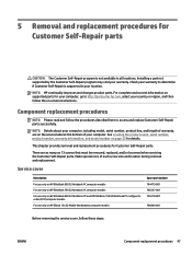
..., including model, serial number, product key, and length of each screw size and location during removal and replacement. This chapter provides removal and replacement procedures for your computer, go to access and replace Customer Self-Repair parts successfully. Service cover Description For use only on HP EliteBook 850 G2 Notebook PC computer models For use only on HP EliteBook 750 G2 Notebook PC computer models For use only on HP EliteBook 850 G2 Notebook PC and HP EliteBook 750 G2 Notebook PC configure to determine...
..., including model, serial number, product key, and length of each screw size and location during removal and replacement. This chapter provides removal and replacement procedures for your computer, go to access and replace Customer Self-Repair parts successfully. Service cover Description For use only on HP EliteBook 850 G2 Notebook PC computer models For use only on HP EliteBook 750 G2 Notebook PC computer models For use only on HP EliteBook 850 G2 Notebook PC and HP EliteBook 750 G2 Notebook PC configure to determine...
Maintenance and Service Guide
Page 75
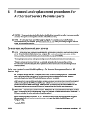
... -screen instructions. IMPORTANT: A service agent cannot retrieve the PIN from the same website before you can access HP Computer Setup and start the Windows operating system. If a PIN is returned for Authorized Service Provider only parts. To disable AORM: ENWW Component replacement procedures 65 Make special note of your computer, go to unlock the device. 6 Removal and replacement procedures for encrypted self-encrypting drives). AORM can perform a secure BIOS level lock...
... -screen instructions. IMPORTANT: A service agent cannot retrieve the PIN from the same website before you can access HP Computer Setup and start the Windows operating system. If a PIN is returned for Authorized Service Provider only parts. To disable AORM: ENWW Component replacement procedures 65 Make special note of your computer, go to unlock the device. 6 Removal and replacement procedures for encrypted self-encrypting drives). AORM can perform a secure BIOS level lock...

Maintenance and Service Guide
Page 76
... on HP EliteBook 750 G2 Notebook PC computer models ● 796897-001 - See Display assembly on the computer. Disconnect all external devices from the computer. 3. Remove the display bezel: 1. Remove the battery (see Service cover on or restart the device, and then press esc while the "Press the ESC key for Startup Menu" message is available using the following section provides instructions on removing the display assembly and other display assembly subcomponents. Remove the...
... on HP EliteBook 750 G2 Notebook PC computer models ● 796897-001 - See Display assembly on the computer. Disconnect all external devices from the computer. 3. Remove the display bezel: 1. Remove the battery (see Service cover on or restart the device, and then press esc while the "Press the ESC key for Startup Menu" message is available using the following section provides instructions on removing the display assembly and other display assembly subcomponents. Remove the...

Maintenance and Service Guide
Page 86
... which the card reader board cable is connected, and then disconnect the card reader board cable from the card reader board. 3. NFC module (see Keyboard on page 75 ,where applicable) Remove the card reader board: 1. Card reader board Description Fan (includes cable) Spare part number 784779-001 Before removing the card reader board, follow these steps: 1. Disconnect the power from the computer by unplugging the power cord from the computer. 4. Battery (see Service cover on , and then shut it from the top cover (3). (The card reader board is...
... which the card reader board cable is connected, and then disconnect the card reader board cable from the card reader board. 3. NFC module (see Keyboard on page 75 ,where applicable) Remove the card reader board: 1. Card reader board Description Fan (includes cable) Spare part number 784779-001 Before removing the card reader board, follow these steps: 1. Disconnect the power from the computer by unplugging the power cord from the computer. 4. Battery (see Service cover on , and then shut it from the top cover (3). (The card reader board is...

Maintenance and Service Guide
Page 111
... Starting Computer Setup NOTE: An external keyboard or mouse connected to navigate and make selections in Computer Setup. 2. Press f10 to enter Computer Setup. Press f10 to enter Computer Setup. Turn on the system (such as disk drives, display, keyboard, mouse, and printer). Errors can be used with Computer Setup only if USB legacy support is displayed at the bottom of the screen. NOTE: Use extreme care when making changes in Computer Setup, follow these steps: 1. Computer Setup includes settings for Startup Menu...
... Starting Computer Setup NOTE: An external keyboard or mouse connected to navigate and make selections in Computer Setup. 2. Press f10 to enter Computer Setup. Press f10 to enter Computer Setup. Turn on the system (such as disk drives, display, keyboard, mouse, and printer). Errors can be used with Computer Setup only if USB legacy support is displayed at the bottom of the screen. NOTE: Use extreme care when making changes in Computer Setup, follow these steps: 1. Computer Setup includes settings for Startup Menu...

Maintenance and Service Guide
Page 112
... press enter. or - Follow the on -screen instructions. Use the arrow keys to select Main > Restore Defaults. 4. NOTE: Your password settings and security settings are not changed when you restore the factory settings. 102 Chapter 7 Computer Setup (BIOS), MultiBoot, and HP PC Hardware Diagnostics (UEFI) ENWW ● To select a menu or a menu item, use the tab key and the keyboard arrow keys and then press enter, or use a pointing device to click the item. ● To scroll up...
... press enter. or - Follow the on -screen instructions. Use the arrow keys to select Main > Restore Defaults. 4. NOTE: Your password settings and security settings are not changed when you restore the factory settings. 102 Chapter 7 Computer Setup (BIOS), MultiBoot, and HP PC Hardware Diagnostics (UEFI) ENWW ● To select a menu or a menu item, use the tab key and the keyboard arrow keys and then press enter, or use a pointing device to click the item. ● To scroll up...
Maintenance and Service Guide
Page 113
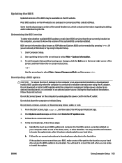
... troubleshooting the file. Do not shut down the computer or initiate Sleep. Do not insert, remove, connect, or disconnect any device, cable, or cord. 1. At the download area, follow the on battery power, docked in compressed files called SoftPaqs. BIOS version information (also known as ROM date and System BIOS) can be available on -screen instructions. 4. Use a pointing device or the arrow keys to select Main > Ignore Changes...
... troubleshooting the file. Do not shut down the computer or initiate Sleep. Do not insert, remove, connect, or disconnect any device, cable, or cord. 1. At the download area, follow the on battery power, docked in compressed files called SoftPaqs. BIOS version information (also known as ROM date and System BIOS) can be available on -screen instructions. 4. Use a pointing device or the arrow keys to select Main > Ignore Changes...

Maintenance and Service Guide
Page 115
... drives, a network interface card (NIC), hard drives, and USB devices. Use a pointing device or the arrow keys to select one of the screen, and then pressing f9 to enter the Boot Device Options menu. ● To use MultiBoot Express to set the computer to select a boot device. Using MultiBoot About the boot device order As the computer starts, the system attempts to enter Computer Setup. 3. This feature prompts you to prompt you for Startup Menu" message is displayed at the factory, controls...
... drives, a network interface card (NIC), hard drives, and USB devices. Use a pointing device or the arrow keys to select one of the screen, and then pressing f9 to enter the Boot Device Options menu. ● To use MultiBoot Express to set the computer to select a boot device. Using MultiBoot About the boot device order As the computer starts, the system attempts to enter Computer Setup. 3. This feature prompts you to prompt you for Startup Menu" message is displayed at the factory, controls...

Maintenance and Service Guide
Page 117
... tool opens, use the keyboard arrow keys to select the type of diagnostic test you want to Support, located at the top of the page, and then click Download Drivers. b. Point to run diagnostic tests to expire. The tool runs outside the operating system so that it can isolate hardware failures from defaulting to a USB device: Option 1: HP PC Diagnostics homepage- Connected USB drive NOTE: To download the HP PC Hardware Diagnostics...
... tool opens, use the keyboard arrow keys to select the type of diagnostic test you want to Support, located at the top of the page, and then click Download Drivers. b. Point to run diagnostic tests to expire. The tool runs outside the operating system so that it can isolate hardware failures from defaulting to a USB device: Option 1: HP PC Diagnostics homepage- Connected USB drive NOTE: To download the HP PC Hardware Diagnostics...

Maintenance and Service Guide
Page 126
... memory retain data when power is protected protected device via the host processor. recommends password keyboard protecting the F10 Setup controller data. To run Secure Erase, follow these steps: a. Non-volatile memory usage Non Volatile Memory Type Amount (Size) HP Sure Start flash (select models only) 2 MB Real Time Clock (RTC) battery backed-up CMOS configuration memory (CMOS) 256 Bytes Does this This memory is removed? by using the BIOS Setup Secure Erase command option...
... memory retain data when power is protected protected device via the host processor. recommends password keyboard protecting the F10 Setup controller data. To run Secure Erase, follow these steps: a. Non-volatile memory usage Non Volatile Memory Type Amount (Size) HP Sure Start flash (select models only) 2 MB Real Time Clock (RTC) battery backed-up CMOS configuration memory (CMOS) 256 Bytes Does this This memory is removed? by using the BIOS Setup Secure Erase command option...

Maintenance and Service Guide
Page 127
... when power is this memory when the information. on -screen instructions.) Does this mouse, & system BIOS is installed in an inappropriate manner can be entered at the factory. vendor. Yes Stores Management Engine Code is The Intel chipset is Management programmed at the utility is required for code (keyboard, Code is updated when the writing data to the space. Configuration data and data to http://www.hp.com/ support, and...
... when power is this memory when the information. on -screen instructions.) Does this mouse, & system BIOS is installed in an inappropriate manner can be entered at the factory. vendor. Yes Stores Management Engine Code is The Intel chipset is Management programmed at the utility is required for code (keyboard, Code is updated when the writing data to the space. Configuration data and data to http://www.hp.com/ support, and...

Maintenance and Service Guide
Page 129
... resetting the CMOS configuration memory return the PC back to perform the write function. 4. b. This EEPROM cannot be written? Does the "Firmware Hub for returning the BIOS settings to question and answer 1 and follow the instructions for System BIOS" contain the BIOS program? How would this data be written to when the memory module is required to factory defaults? A utility is installed in Intel-based system boards"? Questions...
... resetting the CMOS configuration memory return the PC back to perform the write function. 4. b. This EEPROM cannot be written? Does the "Firmware Hub for returning the BIOS settings to question and answer 1 and follow the instructions for System BIOS" contain the BIOS program? How would this data be written to when the memory module is required to factory defaults? A utility is installed in Intel-based system boards"? Questions...

Maintenance and Service Guide
Page 137
... audio, product description 7 audio-in (microphone) jack 23 audio-out (headphone) jack 23 B base enclosure removal 71 spare part numbers 36, 71 battery removal 49 spare part numbers 31, 49 BIOS determining version 103 downloading an update 103 updating 103 Blu-ray ROM DVD±RW SuperMulti DL Drive precautions 42 buttons pointing stick 20, 21 power 17 TouchPad 20, 21 TouchPad on/off 20 volume mute 18 wireless 18 C cables, service considerations 41 caps lock light 19 card reader board removal 76 spare part number...
... audio, product description 7 audio-in (microphone) jack 23 audio-out (headphone) jack 23 B base enclosure removal 71 spare part numbers 36, 71 battery removal 49 spare part numbers 31, 49 BIOS determining version 103 downloading an update 103 updating 103 Blu-ray ROM DVD±RW SuperMulti DL Drive precautions 42 buttons pointing stick 20, 21 power 17 TouchPad 20, 21 TouchPad on/off 20 volume mute 18 wireless 18 C cables, service considerations 41 caps lock light 19 card reader board removal 76 spare part number...
Maintenance and Service Guide
Page 138
... Windows applications 19 L legacy support, USB 101 lights AC adapter/battery 21 caps lock 19 hard drive 21 microphone mute 20 mute 20 num lock 20 power 19, 21 RJ-45 (network) 23 TouchPad 20 webcam 16 wireless 20, 21 M mass storage device precautions 42 memory nonvolatile 115 volatile 115 memory card reader 23 memory module removal 58 spare part numbers 32, 58 memory, product description 3, 4 microphone 16 product description 7 microphone (audio-in) jack 23 microphone module removal 69 spare part number 37, 69 microphone mute light 20 monitor port...
... Windows applications 19 L legacy support, USB 101 lights AC adapter/battery 21 caps lock 19 hard drive 21 microphone mute 20 mute 20 num lock 20 power 19, 21 RJ-45 (network) 23 TouchPad 20 webcam 16 wireless 20, 21 M mass storage device precautions 42 memory nonvolatile 115 volatile 115 memory card reader 23 memory module removal 58 spare part numbers 32, 58 memory, product description 3, 4 microphone 16 product description 7 microphone (audio-in) jack 23 microphone module removal 69 spare part number 37, 69 microphone mute light 20 monitor port...

Maintenance and Service Guide
Page 139
... TouchPad light 20 TouchPad on/off button 20 TouchPad zone 20 transporting guidelines 44 U USB 3.0 charging port (powered) 22 USB 3.0 port 22, 23 USB legacy support 101 USB port 22, 23 USB/VGA connector board removal 79 spare part number 31, 79 V vents 22, 24 video, product description 7 volume mute button 18 W webcam 16 webcam light 16 webcam/microphone module removal 69 spare part number 37, 69 Windows Refresh 114 Reset 114 Windows applications key 19 Windows key 18 Windows operating system DVD 113 wireless antenna location 16 removal 98 spare part number 37, 99 wireless button 18 wireless...
... TouchPad light 20 TouchPad on/off button 20 TouchPad zone 20 transporting guidelines 44 U USB 3.0 charging port (powered) 22 USB 3.0 port 22, 23 USB legacy support 101 USB port 22, 23 USB/VGA connector board removal 79 spare part number 31, 79 V vents 22, 24 video, product description 7 volume mute button 18 W webcam 16 webcam light 16 webcam/microphone module removal 69 spare part number 37, 69 Windows Refresh 114 Reset 114 Windows applications key 19 Windows key 18 Windows operating system DVD 113 wireless antenna location 16 removal 98 spare part number 37, 99 wireless button 18 wireless...


