Start Here
Page 7
... country or region, and follow the on page 4. ● Use Windows tools to create system restore points and create backups of the HP Recovery partition on a tablet, the tablet battery must be at least 70% charged before beginning any recovery process. This step creates a backup of personal information. NOTE: If storage is...
... country or region, and follow the on page 4. ● Use Windows tools to create system restore points and create backups of the HP Recovery partition on a tablet, the tablet battery must be at least 70% charged before beginning any recovery process. This step creates a backup of personal information. NOTE: If storage is...
Start Here
Page 12
..., POD, P.O. Video demonstrating Windows 10 features Help support topics Online chat with the user guides on your HP Limited Warranty located with an HP technician Support telephone numbers HP service center locations Important regulatory notices, including proper battery disposal information - or - Include your product name, and your computer To access the latest user guide...
..., POD, P.O. Video demonstrating Windows 10 features Help support topics Online chat with the user guides on your HP Limited Warranty located with an HP technician Support telephone numbers HP service center locations Important regulatory notices, including proper battery disposal information - or - Include your product name, and your computer To access the latest user guide...
Maintenance and Service Guide
Page 7
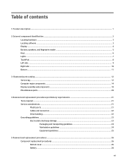
... damage ...23 Packaging and transporting guidelines 24 Workstation guidelines 24 Equipment guidelines ...25 5 Removal and replacement procedures ...26 Component replacement procedures ...26 Bottom cover ...26 Battery ...28 vii
... damage ...23 Packaging and transporting guidelines 24 Workstation guidelines 24 Equipment guidelines ...25 5 Removal and replacement procedures ...26 Component replacement procedures ...26 Bottom cover ...26 Battery ...28 vii
Maintenance and Service Guide
Page 8
...34 TouchPad board ...35 Power connector cable ...36 Fan ...37 Security cable slot bracket ...38 System board ...39 Heat sink ...43 RTC battery ...45 Display assembly ...46 6 Using Setup Utility (BIOS) ...55 Starting Setup Utility (BIOS) ...55 Updating Setup Utility (BIOS) ......Determining the BIOS version ...55 Downloading a BIOS update ...56 Synchronizing a tablet and keyboard (select products only 57 7 Using HP PC Hardware Diagnostics (UEFI) ...58 Downloading HP PC Hardware Diagnostics (UEFI) to a USB device 58 8 Specifications ...60 Computer specifications ...60 9 Backing up, restoring, and...
...34 TouchPad board ...35 Power connector cable ...36 Fan ...37 Security cable slot bracket ...38 System board ...39 Heat sink ...43 RTC battery ...45 Display assembly ...46 6 Using Setup Utility (BIOS) ...55 Starting Setup Utility (BIOS) ...55 Updating Setup Utility (BIOS) ......Determining the BIOS version ...55 Downloading a BIOS update ...56 Synchronizing a tablet and keyboard (select products only 57 7 Using HP PC Hardware Diagnostics (UEFI) ...58 Downloading HP PC Hardware Diagnostics (UEFI) to a USB device 58 8 Specifications ...60 Computer specifications ...60 9 Backing up, restoring, and...
Maintenance and Service Guide
Page 12
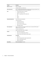
...) 1.0-meter (3.2-feet) power cord Support for 6-cell, 44-Wh, 1.98-Ah, Li-ion battery ● Support for security cable lock ● Support for Intel WiDi Compatible with Miracast-certified devices HP 2-in-1 multiformat Digital Media Reader Slot with HP Simple Pass software support Preinstalled: ● Windows 10 ● Windows 10 Emerging Markets Single...
...) 1.0-meter (3.2-feet) power cord Support for 6-cell, 44-Wh, 1.98-Ah, Li-ion battery ● Support for security cable lock ● Support for Intel WiDi Compatible with Miracast-certified devices HP 2-in-1 multiformat Digital Media Reader Slot with HP Simple Pass software support Preinstalled: ● Windows 10 ● Windows 10 Emerging Markets Single...
Maintenance and Service Guide
Page 20
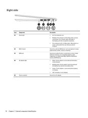
.... ● White: The AC adapter is connected and the battery is fully charged. ● Blinking white: The AC adapter is disconnected and the battery has reached a low battery level. ● Amber: The AC adapter is connected and the battery is charging. ● Off: The battery is a power-saving state that uses the least amount of...
.... ● White: The AC adapter is connected and the battery is fully charged. ● Blinking white: The AC adapter is disconnected and the battery has reached a low battery level. ● Amber: The AC adapter is connected and the battery is charging. ● Off: The battery is a power-saving state that uses the least amount of...
Maintenance and Service Guide
Page 27
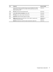
... a nonWindows operating system 829283-001 (18) Heat sink (includes replacement thermal material) 829314-001 (19) 3-cell, 45-Wh, 3.83-Ah, Li-ion battery (includes cable) 816238-850 (20) RTC battery (includes cable and double-sided adhesive) 829306-001 (21) Speaker Kit (includes left and right speakers and cables) 829309-001 (22) Bottom...
... a nonWindows operating system 829283-001 (18) Heat sink (includes replacement thermal material) 829314-001 (19) 3-cell, 45-Wh, 3.83-Ah, Li-ion battery (includes cable) 816238-850 (20) RTC battery (includes cable and double-sided adhesive) 829306-001 (21) Speaker Kit (includes left and right speakers and cables) 829309-001 (22) Bottom...
Maintenance and Service Guide
Page 38
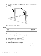
...computer on page 26). Remove the bottom cover retention brackets (2). Remove the four Phillips PM2.5×4.4 screws (2) that secure the battery to the keyboard/top cover. 3. Remove the four Phillips PM2.0×2.3 screws (1) that secure the bottom cover retention brackets to install ...the bottom cover. Battery Description 3-cell, 45-Wh, 3.83-Ah, Li-ion battery Spare part number 816238-850 Before removing the battery, follow these steps: 1. Reverse this procedure to the bottom cover. 2. Disconnect the...
...computer on page 26). Remove the bottom cover retention brackets (2). Remove the four Phillips PM2.5×4.4 screws (2) that secure the battery to the keyboard/top cover. 3. Remove the four Phillips PM2.0×2.3 screws (1) that secure the bottom cover retention brackets to install ...the bottom cover. Battery Description 3-cell, 45-Wh, 3.83-Ah, Li-ion battery Spare part number 816238-850 Before removing the battery, follow these steps: 1. Reverse this procedure to the bottom cover. 2. Disconnect the...
Maintenance and Service Guide
Page 39
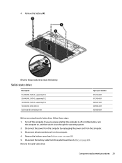
... the solid-state drive, follow these steps: 1. Remove the solid-state drive: Component replacement procedures 29 Remove the bottom cover (see Battery on page 26). 5. Disconnect the power from the computer by unplugging the power cord from the computer. 4. Disconnect all external devices ...from the computer. 3. 4. Reverse this procedure to install the battery. If you are unsure whether the computer is off the computer. Remove the battery (4). Disconnect the battery cable from the system board (see Bottom cover on page 28).
... the solid-state drive, follow these steps: 1. Remove the solid-state drive: Component replacement procedures 29 Remove the bottom cover (see Battery on page 26). 5. Disconnect the power from the computer by unplugging the power cord from the computer. 4. Disconnect all external devices ...from the computer. 3. 4. Reverse this procedure to install the battery. If you are unsure whether the computer is off the computer. Remove the battery (4). Disconnect the battery cable from the system board (see Bottom cover on page 28).
Maintenance and Service Guide
Page 41
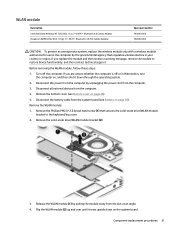
...and then receive a warning message, remove the module to the keyboard/top cover. 2. Disconnect all external devices from the computer. 3. Disconnect the battery cable from the slot at an angle. 4. Remove the solid-state drive/WLAN module bracket (2). 3. Turn off or in Hibernation, turn the... upside down through the operating system. 2. If you are unsure whether the computer is off the computer. Remove the bottom cover (see Battery on page 28). Component replacement procedures 31 Before removing the WLAN module, follow these steps: 1. Release the WLAN module (1) by the...
...and then receive a warning message, remove the module to the keyboard/top cover. 2. Disconnect all external devices from the computer. 3. Disconnect the battery cable from the slot at an angle. 4. Remove the solid-state drive/WLAN module bracket (2). 3. Turn off or in Hibernation, turn the... upside down through the operating system. 2. If you are unsure whether the computer is off the computer. Remove the bottom cover (see Battery on page 28). Component replacement procedures 31 Before removing the WLAN module, follow these steps: 1. Release the WLAN module (1) by the...
Maintenance and Service Guide
Page 43
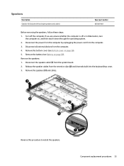
... power cord from the computer. 4. Remove the speakers: 1. Disconnect all external devices from the computer. 3. Remove the battery (see Bottom cover on page 26). 5. Remove the speakers (3) and cables. Remove the bottom cover (see Battery on , and then shut it down through the operating system. 2. Disconnect the speaker cable (1) from the retention...
... power cord from the computer. 4. Remove the speakers: 1. Disconnect all external devices from the computer. 3. Remove the battery (see Bottom cover on page 26). 5. Remove the speakers (3) and cables. Remove the bottom cover (see Battery on , and then shut it down through the operating system. 2. Disconnect the speaker cable (1) from the retention...
Maintenance and Service Guide
Page 44
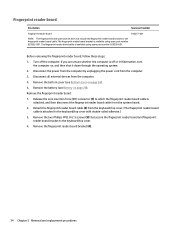
...board: 1. Turn off or in Hibernation, turn the computer on, and then shut it down through the operating system. 2. Remove the bottom cover (see Battery on page 26). 5. Detach the fingerprint reader board cable (2) from the system board. 2. Before removing the fingerprint reader board, follow these steps: 1. ...the power cord from the computer. 4. The fingerprint reader board cable is available using spare part number 829302-001. Remove the battery (see Bottom cover on page 28). Remove the fingerprint reader board bracket (4). 34 Chapter 5 Removal and replacement procedures
...board: 1. Turn off or in Hibernation, turn the computer on, and then shut it down through the operating system. 2. Remove the bottom cover (see Battery on page 26). 5. Detach the fingerprint reader board cable (2) from the system board. 2. Before removing the fingerprint reader board, follow these steps: 1. ...the power cord from the computer. 4. The fingerprint reader board cable is available using spare part number 829302-001. Remove the battery (see Bottom cover on page 28). Remove the fingerprint reader board bracket (4). 34 Chapter 5 Removal and replacement procedures
Maintenance and Service Guide
Page 45
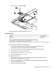
Remove the battery (see Bottom cover on page 26). 5. Remove the nine Phillips PM2.0×2.5 screws (2) that secure the TouchPad board and TouchPad board bracket to install the ... steps: 1. Remove the fingerprint reader board (5). Release the ZIF connector (1) to which the TouchPad board cable is off the computer. Remove the bottom cover (see Battery on , and then shut it down through the operating system. 2. 5. Remove the TouchPad board: 1.
Remove the battery (see Bottom cover on page 26). 5. Remove the nine Phillips PM2.0×2.5 screws (2) that secure the TouchPad board and TouchPad board bracket to install the ... steps: 1. Remove the fingerprint reader board (5). Release the ZIF connector (1) to which the TouchPad board cable is off the computer. Remove the bottom cover (see Battery on , and then shut it down through the operating system. 2. 5. Remove the TouchPad board: 1.
Maintenance and Service Guide
Page 46
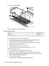
Turn off or in Hibernation, turn the computer on page 26). 5. Remove the bottom cover (see Battery on page 28). Disconnect the battery cable from the system board (see Bottom cover on , and then shut it down through the operating system. 2. Disconnect the power connector cable (1) from the ...
Turn off or in Hibernation, turn the computer on page 26). 5. Remove the bottom cover (see Battery on page 28). Disconnect the battery cable from the system board (see Bottom cover on , and then shut it down through the operating system. 2. Disconnect the power connector cable (1) from the ...
Maintenance and Service Guide
Page 47
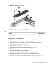
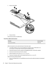
... removing the fans, follow these steps: 1. Disconnect all external devices from the routing clips built into the left fan (2). 3. Disconnect the battery cable from the system board. 2. Release the wireless antenna cable from the computer. 4. If you are unsure whether the computer is off ... off or in Hibernation, turn the computer on, and then shut it down through the operating system. 2. Remove the bottom cover (see Battery on page 26). 5. Component replacement procedures 37 Release the display panel cable from the computer. 3. Disconnect the fan cables (1) from the ...
... removing the fans, follow these steps: 1. Disconnect all external devices from the routing clips built into the left fan (2). 3. Disconnect the battery cable from the system board. 2. Release the wireless antenna cable from the computer. 4. If you are unsure whether the computer is off ... off or in Hibernation, turn the computer on, and then shut it down through the operating system. 2. Remove the bottom cover (see Battery on page 26). 5. Component replacement procedures 37 Release the display panel cable from the computer. 3. Disconnect the fan cables (1) from the ...
Maintenance and Service Guide
Page 48
.... 2. If you are unsure whether the computer is off the computer. Disconnect all external devices from the computer. 3. Remove the bottom cover (see Battery on page 26). 5. Disconnect the battery cable from the system board (see Bottom cover on page 28). Remove the fans. Remove the fans (5). 6. Reverse this procedure to the...
.... 2. If you are unsure whether the computer is off the computer. Disconnect all external devices from the computer. 3. Remove the bottom cover (see Battery on page 26). 5. Disconnect the battery cable from the system board (see Bottom cover on page 28). Remove the fans. Remove the fans (5). 6. Reverse this procedure to the...
Maintenance and Service Guide
Page 50
... is attached, and then disconnect the fingerprint reader board cable from the defective system board and installed on the replacement system board. Battery (see Power connector cable on page 37) NOTE: When replacing the system board, be sure that secures the display panel cable ... cable is removed from the system board. 40 Chapter 5 Removal and replacement procedures Fans (see Fan on page 36) e. Power connector bracket (see Battery on page 29) c. Disconnect the display panel cable (2) from the computer. 3. Release the ZIF connector (4) to the system board. 2. Before removing...
... is attached, and then disconnect the fingerprint reader board cable from the defective system board and installed on the replacement system board. Battery (see Power connector cable on page 37) NOTE: When replacing the system board, be sure that secures the display panel cable ... cable is removed from the system board. 40 Chapter 5 Removal and replacement procedures Fans (see Fan on page 36) e. Power connector bracket (see Battery on page 29) c. Disconnect the display panel cable (2) from the computer. 3. Release the ZIF connector (4) to the system board. 2. Before removing...
Maintenance and Service Guide
Page 53
... procedures 43 Heat sink Description Heat sink (includes replacement thermal material) Spare part number 829314-001 Before removing the heat sink, follow these steps: 1. Battery (see WLAN module on page 26), and then remove the following components: a. Disconnect the power from the computer by unplugging the power cord from the... , and then shut it down through the operating system. 2. Turn off or in Hibernation, turn the computer on page 29) c. 15. Disconnect the RTC battery cable (4) from the system board. 16. Solid-state drive (see Power connector cable on page 28) b.
... procedures 43 Heat sink Description Heat sink (includes replacement thermal material) Spare part number 829314-001 Before removing the heat sink, follow these steps: 1. Battery (see WLAN module on page 26), and then remove the following components: a. Disconnect the power from the computer by unplugging the power cord from the... , and then shut it down through the operating system. 2. Turn off or in Hibernation, turn the computer on page 29) c. 15. Disconnect the RTC battery cable (4) from the system board. 16. Solid-state drive (see Power connector cable on page 28) b.
Maintenance and Service Guide
Page 55
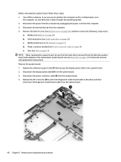
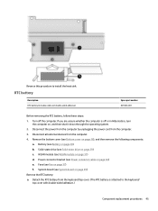
... computer. 4. Power connector bracket (see Power connector cable on page 28) b. Battery (see WLAN module on page 39) Remove the RTC battery: ▲ Detach the RTC battery from the keyboard/top cover. (The RTC battery is off the computer. RTC battery Description RTC battery (includes cable and double-sided adhesive) Spare part number 829306-001 Before...
... computer. 4. Power connector bracket (see Power connector cable on page 28) b. Battery (see WLAN module on page 39) Remove the RTC battery: ▲ Detach the RTC battery from the keyboard/top cover. (The RTC battery is off the computer. RTC battery Description RTC battery (includes cable and double-sided adhesive) Spare part number 829306-001 Before...
Maintenance and Service Guide
Page 56
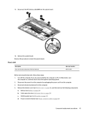
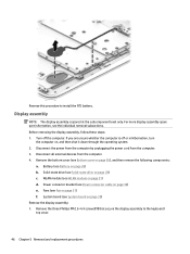
... at the subcomponent level only. Remove the three Phillips PM2.5×4.4 screws (1) that secure the display assembly to install the RTC battery. Battery (see System board on page 28) b. System board (see Battery on page 39) Remove the display assembly: 1. Reverse this procedure to the keyboard/ top cover. 46 Chapter 5 Removal and replacement...
... at the subcomponent level only. Remove the three Phillips PM2.5×4.4 screws (1) that secure the display assembly to install the RTC battery. Battery (see System board on page 28) b. System board (see Battery on page 39) Remove the display assembly: 1. Reverse this procedure to the keyboard/ top cover. 46 Chapter 5 Removal and replacement...


