Service Guide
Page 17
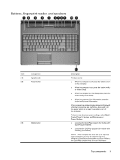
... for more about your power settings, select Start > Control Panel > System and Maintenance > Power Options. ● Launches the QuickPlay program (for models with DVDPlay preinstalled). Buttons, fingerprint reader, and speakers Item (1) (2) Component Speakers (2) Power button (3) Media button Description Produce sound. ● When the computer is off, press the button to turn on the computer. ● When the computer is on, press the button briefly to initiate Sleep. ● When the...
... for more about your power settings, select Start > Control Panel > System and Maintenance > Power Options. ● Launches the QuickPlay program (for models with DVDPlay preinstalled). Buttons, fingerprint reader, and speakers Item (1) (2) Component Speakers (2) Power button (3) Media button Description Produce sound. ● When the computer is off, press the button to turn on the computer. ● When the computer is on, press the button briefly to initiate Sleep. ● When the...
Service Guide
Page 21
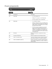
... are fully charged. If the computer is the only available power source has reached a low battery level. Receives a signal from the HP Remote Control. Connects an optional computer headset microphone, stereo array microphone, or monaural microphone. Front components Item (1) Component Power light (2) Battery light (3) Drive light (4) Consumer infrared lens (5) Audio-in (microphone) jack (6) Audio-out (headphone) jacks (2) Description ● On: The computer is on. ● Blinking: The computer is in the Sleep state...
... are fully charged. If the computer is the only available power source has reached a low battery level. Receives a signal from the HP Remote Control. Connects an optional computer headset microphone, stereo array microphone, or monaural microphone. Front components Item (1) Component Power light (2) Battery light (3) Drive light (4) Consumer infrared lens (5) Audio-in (microphone) jack (6) Audio-out (headphone) jacks (2) Description ● On: The computer is on. ● Blinking: The computer is in the Sleep state...
Service Guide
Page 23
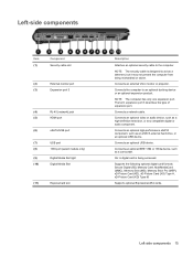
... accessed. Left-side components 15 NOTE: The security cable is being mishandled or stolen. Connects the computer to act as an eSATA external hard drive, or an optional USB device. Connects a network cable. On: A digital card is designed to an optional docking device or an optional expansion product. Left-side components Item (1) Component Security cable slot (2) External monitor port (3) Expansion port 3 (4) RJ-45 (network) jack (5) HDMI port (6) eSATA/USB port (7) USB port (8) 1394 port (select models only) (9) Digital Media Slot light (10) Digital Media Slot...
... accessed. Left-side components 15 NOTE: The security cable is being mishandled or stolen. Connects the computer to act as an eSATA external hard drive, or an optional USB device. Connects a network cable. On: A digital card is designed to an optional docking device or an optional expansion product. Left-side components Item (1) Component Security cable slot (2) External monitor port (3) Expansion port 3 (4) RJ-45 (network) jack (5) HDMI port (6) eSATA/USB port (7) USB port (8) 1394 port (select models only) (9) Digital Media Slot light (10) Digital Media Slot...
Service Guide
Page 25
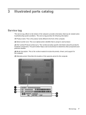
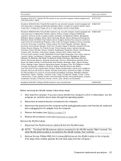
... the computer. (5) Warranty period: Describes the duration of the computer. (2) Serial number (s/n): This is an alphanumeric identifier that is the number needed . (4) Model description: This is unique to locate documents, drivers, and support for the computer. Service tag 17 The part number helps a service technician to determine what components and parts are needed to each product. (3) Part number/Product number (p/n): This number provides specific information about the product's hardware components.
... the computer. (5) Warranty period: Describes the duration of the computer. (2) Serial number (s/n): This is an alphanumeric identifier that is the number needed . (4) Model description: This is unique to locate documents, drivers, and support for the computer. Service tag 17 The part number helps a service technician to determine what components and parts are needed to each product. (3) Part number/Product number (p/n): This number provides specific information about the product's hardware components.
Service Guide
Page 45
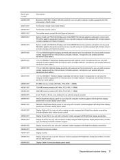
... for use only with computer models equipped with BrightView display assemblies Display bezel for use only with computer models equipped with BrightView display assemblies (includes logo and display lid switch actuator magnet) Display enclosure for use only with computer models equipped with BrightView display assemblies Webcam/microphone module Display inverter Display hinges for use only with computer models equipped with BrightView display assemblies (includes left and right hinges) Display Cable Kit (includes display panel cable) Sequential part number listing...
... for use only with computer models equipped with BrightView display assemblies Display bezel for use only with computer models equipped with BrightView display assemblies (includes logo and display lid switch actuator magnet) Display enclosure for use only with computer models equipped with BrightView display assemblies Webcam/microphone module Display inverter Display hinges for use only with computer models equipped with BrightView display assemblies (includes left and right hinges) Display Cable Kit (includes display panel cable) Sequential part number listing...
Service Guide
Page 46
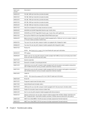
... port, but not a modem module or a TV tuner module (includes 6 rubber feet) Top cover for use only with computer models not equipped with a fingerprint reader Top cover for use only with computer models equipped with a fingerprint reader Plastics Kit NOTE: See Plastics Kit on page 32 for more Cable Kit spare part information. RTC battery Switch cover for use only with computer models equipped with AMD processors (includes power button board...
... port, but not a modem module or a TV tuner module (includes 6 rubber feet) Top cover for use only with computer models not equipped with a fingerprint reader Top cover for use only with computer models equipped with a fingerprint reader Plastics Kit NOTE: See Plastics Kit on page 32 for more Cable Kit spare part information. RTC battery Switch cover for use only with computer models equipped with AMD processors (includes power button board...
Service Guide
Page 57
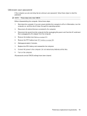
... passwords and all external devices connected to the computer. If you are unsure whether the computer is off or in Hibernation, turn the computer on page 60). 6. Remove the RTC battery (see Battery on the computer. Preliminary replacement requirements 49 Replace the RTC battery and reassemble the computer. 8. Connect AC power to the computer. 3. Unknown user password If the computer you are servicing has an unknown user password...
... passwords and all external devices connected to the computer. If you are unsure whether the computer is off or in Hibernation, turn the computer on page 60). 6. Remove the RTC battery (see Battery on the computer. Preliminary replacement requirements 49 Replace the RTC battery and reassemble the computer. 8. Connect AC power to the computer. 3. Unknown user password If the computer you are servicing has an unknown user password...
Service Guide
Page 58
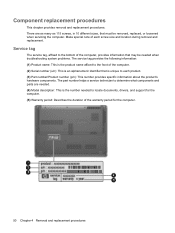
... the number needed . (4) Model description: This is unique to locate documents, drivers, and support for the computer. 50 Chapter 4 Removal and replacement procedures There are needed to each screw size and location during removal and replacement. Make special note of the warranty period for the computer. (5) Warranty period: Describes the duration of each product. (3) Part number/Product number (p/n): This number provides specific information about the product's hardware components. Component replacement...
... the number needed . (4) Model description: This is unique to locate documents, drivers, and support for the computer. 50 Chapter 4 Removal and replacement procedures There are needed to each screw size and location during removal and replacement. Make special note of the warranty period for the computer. (5) Warranty period: Describes the duration of each product. (3) Part number/Product number (p/n): This number provides specific information about the product's hardware components. Component replacement...
Service Guide
Page 66
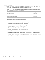
... PAL jack). Shut down through the operating system. 2. The TV tuner module cable is off or in the Cable Kit, spare part number 480474-001. TV tuner module NOTE: The TV tuner module spare part kits do not include a TV tuner module cable. Disconnect all external devices connected to the computer. (The edge of the module opposite the slot rises away from the computer. 4. Remove the battery (see Hard drive on...
... PAL jack). Shut down through the operating system. 2. The TV tuner module cable is off or in the Cable Kit, spare part number 480474-001. TV tuner module NOTE: The TV tuner module spare part kits do not include a TV tuner module cable. Disconnect all external devices connected to the computer. (The edge of the module opposite the slot rises away from the computer. 4. Remove the battery (see Hard drive on...
Service Guide
Page 71
... removing the WLAN module, follow these steps: 1. Remove the battery (see Hard drive on , and then shut it down the computer. Lucia, St. If you are unsure whether the computer is off or in Hibernation, turn the computer on page 56). Disconnect the WLAN antenna cables (1) from the WLAN module. Disconnect all external devices connected to the WLAN module "Main" terminal. Description Spare part number...
... removing the WLAN module, follow these steps: 1. Remove the battery (see Hard drive on , and then shut it down the computer. Lucia, St. If you are unsure whether the computer is off or in Hibernation, turn the computer on page 56). Disconnect the WLAN antenna cables (1) from the WLAN module. Disconnect all external devices connected to the WLAN module "Main" terminal. Description Spare part number...

Service Guide
Page 96
....5×4.0 screws (2) that secure the TouchPad button board to the computer. 3. Disconnect all external devices connected to the top cover. 4. Bluetooth module cable NOTE: The Bluetooth module cable is attached, and then disconnect the cable from the computer. 88 Chapter 4 Removal and replacement procedures If you . 2. Display assembly (see Speaker assembly on , and then shut it down through the operating system. 2. Disconnect the power from the computer by first...
....5×4.0 screws (2) that secure the TouchPad button board to the computer. 3. Disconnect all external devices connected to the top cover. 4. Bluetooth module cable NOTE: The Bluetooth module cable is attached, and then disconnect the cable from the computer. 88 Chapter 4 Removal and replacement procedures If you . 2. Display assembly (see Speaker assembly on , and then shut it down through the operating system. 2. Disconnect the power from the computer by first...

Service Guide
Page 98
... New Zealand Spare part number 461749-001 461749-011 Before removing the modem module, follow these steps: 1. Disconnect the power from the computer by first unplugging the power cord from the AC outlet and then unplugging the AC Adapter from the modem module. 2. Hard drive (see Switch cover on page 56) b. The modem module cable is off or in all external devices connected to the system board. 90 Chapter 4 Removal...
... New Zealand Spare part number 461749-001 461749-011 Before removing the modem module, follow these steps: 1. Disconnect the power from the computer by first unplugging the power cord from the AC outlet and then unplugging the AC Adapter from the modem module. 2. Hard drive (see Switch cover on page 56) b. The modem module cable is off or in all external devices connected to the system board. 90 Chapter 4 Removal...
Service Guide
Page 118
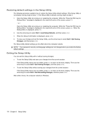
... visible, press esc to return to restore the Setup Utility default settings. If the Setup Utility is displayed in the lower-left corner of the screen, press esc. To save your change and exit the Setup Utility, use the arrow keys to select Exit > Exit Saving Changes, and then press enter. Then use the arrow keys to select Exit > Exit Discarding Changes, and then press enter. When the Startup Menu is displayed, press enter. 4.
... visible, press esc to return to restore the Setup Utility default settings. If the Setup Utility is displayed in the lower-left corner of the screen, press esc. To save your change and exit the Setup Utility, use the arrow keys to select Exit > Exit Saving Changes, and then press enter. Then use the arrow keys to select Exit > Exit Discarding Changes, and then press enter. When the Startup Menu is displayed, press enter. 4.
Service Guide
Page 119
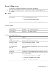
... models only) LAN Power Saving (select models only) Enable/disable the capacitive button tapping sound. Enter, change , or delete an administrator password. System Configuration menu Select To do this Language Support Change the Setup Utility language. Main menu Select System information To do this ● View and change the system time and date. ● View identification information about the computer. ● View specification information about the processor, memory size, system BIOS, and keyboard controller...
... models only) LAN Power Saving (select models only) Enable/disable the capacitive button tapping sound. Enter, change , or delete an administrator password. System Configuration menu Select To do this Language Support Change the Setup Utility language. Main menu Select System information To do this ● View and change the system time and date. ● View identification information about the computer. ● View specification information about the processor, memory size, system BIOS, and keyboard controller...
Service Guide
Page 120
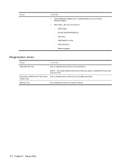
...9679; Internal Network Adapter boot―Enable/disable boot from Internal Network Adapter. ● Boot Order―Set the boot order for: ◦ USB Floppy ◦ Internal CD/DVD ROM Drive ◦ Hard drive ◦ USB Diskette on Key ◦ USB Hard drive ◦ Network adapter Diagnostics menu Select To do this menu option is called the Primary Hard Disk Self Test. models only) Memory Test Run a diagnostic test on a secondary hard drive. Secondary Hard Disk Self Test (select Run a comprehensive self-test on the system memory. 112 Chapter 5 Setup Utility NOTE: On models...
...9679; Internal Network Adapter boot―Enable/disable boot from Internal Network Adapter. ● Boot Order―Set the boot order for: ◦ USB Floppy ◦ Internal CD/DVD ROM Drive ◦ Hard drive ◦ USB Diskette on Key ◦ USB Hard drive ◦ Network adapter Diagnostics menu Select To do this menu option is called the Primary Hard Disk Self Test. models only) Memory Test Run a diagnostic test on a secondary hard drive. Secondary Hard Disk Self Test (select Run a comprehensive self-test on the system memory. 112 Chapter 5 Setup Utility NOTE: On models...
Service Guide
Page 124
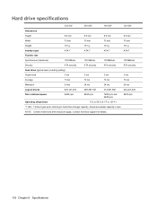
Contact technical support for details. 116 Chapter 6 Specifications Hard drive specifications 320-GB* 250-GB* 160-GB* 120-GB* Dimensions Height 9.5 mm 9.5 mm 9.5 mm 9.5 mm Width 70 mm Weight 101 g Interface type ATA-7 Transfer rate Synchronous (maximum) 100 MB/sec Security ATA security Seek times (typical read, including setting) 70 mm 101 g ATA-7 100 MB/sec ATA security...
Contact technical support for details. 116 Chapter 6 Specifications Hard drive specifications 320-GB* 250-GB* 160-GB* 120-GB* Dimensions Height 9.5 mm 9.5 mm 9.5 mm 9.5 mm Width 70 mm Weight 101 g Interface type ATA-7 Transfer rate Synchronous (maximum) 100 MB/sec Security ATA security Seek times (typical read, including setting) 70 mm 101 g ATA-7 100 MB/sec ATA security...

Service Guide
Page 176
... cables, service considerations 45 Card Reader Power Saving 111 CAT5E cable, spare part number 34, 35 changing the Setup Utility language 109 chipset, product description 1 CMOS clearing 49 components bottom 16 buttons 9 display 7 fingerprint reader 9 front 13 keyboard 11 left-side 15 rear 14 right-side 14 speakers 9 TouchPad 12 computer feet locations 51 spare part number 51 computer specifications 113 connectors, service considerations 45 D Digital Media Slot 15 Digital Media Slot Light 15 diskette drive, precautions 45 display assembly removal...
... cables, service considerations 45 Card Reader Power Saving 111 CAT5E cable, spare part number 34, 35 changing the Setup Utility language 109 chipset, product description 1 CMOS clearing 49 components bottom 16 buttons 9 display 7 fingerprint reader 9 front 13 keyboard 11 left-side 15 rear 14 right-side 14 speakers 9 TouchPad 12 computer feet locations 51 spare part number 51 computer specifications 113 connectors, service considerations 45 D Digital Media Slot 15 Digital Media Slot Light 15 diskette drive, precautions 45 display assembly removal...
Service Guide
Page 177
... display switch 7 displaying system information 109 docking support, product description 5 drive light 13 drives boot order 111 preventing damage 45 DVD±RW and CD-RW Combo Drive precautions 45 removal 54 spare part numbers 25, 33, 38, 54 specifications 118 E electrostatic discharge 46 eSATA/USB port 15 esc key 11 Ethernet, product description 4 exiting the Setup Utility 110 expansion port 3 15 ExpressCard slot 15 ExpressCard slot bezel, illustrated 31 external media cards, product description 5 external monitor port location 15...
... display switch 7 displaying system information 109 docking support, product description 5 drive light 13 drives boot order 111 preventing damage 45 DVD±RW and CD-RW Combo Drive precautions 45 removal 54 spare part numbers 25, 33, 38, 54 specifications 118 E electrostatic discharge 46 eSATA/USB port 15 esc key 11 Ethernet, product description 4 exiting the Setup Utility 110 expansion port 3 15 ExpressCard slot 15 ExpressCard slot bezel, illustrated 31 external media cards, product description 5 external monitor port location 15...
Service Guide
Page 178
... description 4 monitor port location 15 pin assignments 156 mouse, spare part numbers 34, 35 L LAN Power Saving 111 language support 111 left-side components 15 lights battery 13 Digital Media Slot 15 drive 13 optical drive 14 power 13 M mass storage devices, spare part numbers 33 media button 9 memory map specifications 127, 128, 129 memory module location 16 product description 2 removal 64 spare part numbers 26, 37, 64 memory test 112 microphone locations 8 product description 4 microphone jack location 13 pin assignments 155 model name 1 N network jack location 15 pin...
... description 4 monitor port location 15 pin assignments 156 mouse, spare part numbers 34, 35 L LAN Power Saving 111 language support 111 left-side components 15 lights battery 13 Digital Media Slot 15 drive 13 optical drive 14 power 13 M mass storage devices, spare part numbers 33 media button 9 memory map specifications 127, 128, 129 memory module location 16 product description 2 removal 64 spare part numbers 26, 37, 64 memory test 112 microphone locations 8 product description 4 microphone jack location 13 pin assignments 155 model name 1 N network jack location 15 pin...
Service Guide
Page 179
... security cable slot 15 security, product description 6 service considerations 44 service tag 17, 50 serviceability, product description 6 Setup Utility changing the language 109 Diagnostics menu 112 display system information 109 exiting 110 Main menu 111 menus 111 restoring default settings 110 Security menu 111 starting 108 System Configuration memu 111 using 109 solid-state drive (SSD) 149 speaker assembly removal 72 spare part number 20, 38, 72 speaker components 9 speakers 9 specifications Blu-ray Disc ROM Drive...
... security cable slot 15 security, product description 6 service considerations 44 service tag 17, 50 serviceability, product description 6 Setup Utility changing the language 109 Diagnostics menu 112 display system information 109 exiting 110 Main menu 111 menus 111 restoring default settings 110 Security menu 111 starting 108 System Configuration memu 111 using 109 solid-state drive (SSD) 149 speaker assembly removal 72 spare part number 20, 38, 72 speaker components 9 speakers 9 specifications Blu-ray Disc ROM Drive...


