End User License Agreement
Page 2
...rights in this EULA, and if applicable, the Certificate of the Software Product, your upgrade eligibility. 3. You agree that HP and its suppliers and are protected by the Microsoft License Agreement. 2. After upgrading, you may only be governed by law, including but not limited to do so ... comply with the update or supplement. You may not be licensed for commercial timesharing or bureau use a Software Product identified as an upgrade, you fail to the transfer, the end user receiving the transferred product must include all the EULA terms. Upon transfer of Authenticity...
...rights in this EULA, and if applicable, the Certificate of the Software Product, your upgrade eligibility. 3. You agree that HP and its suppliers and are protected by the Microsoft License Agreement. 2. After upgrading, you may only be governed by law, including but not limited to do so ... comply with the update or supplement. You may not be licensed for commercial timesharing or bureau use a Software Product identified as an upgrade, you fail to the transfer, the end user receiving the transferred product must include all the EULA terms. Upon transfer of Authenticity...

Global Limited Warranty and Technical Support
Page 5
...APPLICABLE LAW, IN NO EVENT SHALL HP OR ITS SUPPLIERS BE LIABLE FOR ANY SPECIAL, INCIDENTAL, INDIRECT, OR CONSEQUENTIAL DAMAGES WHATSOEVER (INCLUDING, BUT NOT LIMITED TO, DAMAGES FOR LOSS OF PROFITS OR CONFIDENTIAL OR OTHER INFORMATION, FOR BUSINESS INTERRUPTION, FOR PERSONAL INJURY, FOR ...The defective part must be purchased locally. Some states/jurisdictions do not allow the exclusion or limitation of the HP Option, is installed in the provided shipping material. Service Upgrades HP has a range of time, normally fifteen (15) days. within a defined period of additional support and...
...APPLICABLE LAW, IN NO EVENT SHALL HP OR ITS SUPPLIERS BE LIABLE FOR ANY SPECIAL, INCIDENTAL, INDIRECT, OR CONSEQUENTIAL DAMAGES WHATSOEVER (INCLUDING, BUT NOT LIMITED TO, DAMAGES FOR LOSS OF PROFITS OR CONFIDENTIAL OR OTHER INFORMATION, FOR BUSINESS INTERRUPTION, FOR PERSONAL INJURY, FOR ...The defective part must be purchased locally. Some states/jurisdictions do not allow the exclusion or limitation of the HP Option, is installed in the provided shipping material. Service Upgrades HP has a range of time, normally fifteen (15) days. within a defined period of additional support and...

Global Limited Warranty and Technical Support
Page 5
...PERMITTED BY APPLICABLE LAW, IN NO EVENT SHALL HP OR ITS SUPPLIERS BE LIABLE FOR ANY SPECIAL, INCIDENTAL, INDIRECT, OR CONSEQUENTIAL DAMAGES WHATSOEVER (INCLUDING, BUT NOT LIMITED TO, DAMAGES FOR LOSS OF PROFITS OR CONFIDENTIAL OR OTHER INFORMATION, FOR BUSINESS INTERRUPTION, FOR PERSONAL INJURY, FOR LOSS OF PRIVACY... ANY SUPPLIER HAS BEEN ADVISED OF THE POSSIBILITY OF SUCH DAMAGES AND EVEN IF THE REMEDY FAILS OF ITS ESSENTIAL PURPOSE. Service Upgrades HP has a range of additional support and service coverage for the remaining warranty period of implied warranties, so the above limitation or ...
...PERMITTED BY APPLICABLE LAW, IN NO EVENT SHALL HP OR ITS SUPPLIERS BE LIABLE FOR ANY SPECIAL, INCIDENTAL, INDIRECT, OR CONSEQUENTIAL DAMAGES WHATSOEVER (INCLUDING, BUT NOT LIMITED TO, DAMAGES FOR LOSS OF PROFITS OR CONFIDENTIAL OR OTHER INFORMATION, FOR BUSINESS INTERRUPTION, FOR PERSONAL INJURY, FOR LOSS OF PRIVACY... ANY SUPPLIER HAS BEEN ADVISED OF THE POSSIBILITY OF SUCH DAMAGES AND EVEN IF THE REMEDY FAILS OF ITS ESSENTIAL PURPOSE. Service Upgrades HP has a range of additional support and service coverage for the remaining warranty period of implied warranties, so the above limitation or ...
Hardware Reference Guide - dc7600 CMT
Page 1
Hardware Reference Guide HP Compaq Business PC dc7600 Convertible Minitower Document Part Number: 384568-001 May 2005 This guide provides basic information for upgrading this computer model.
Hardware Reference Guide HP Compaq Business PC dc7600 Convertible Minitower Document Part Number: 384568-001 May 2005 This guide provides basic information for upgrading this computer model.

Hardware Reference Guide - dc7600 CMT
Page 3
... Panel Components 1-3 Keyboard 1-4 Using the Windows Logo Key 1-5 Special Mouse Functions 1-5 Serial Number Location 1-6 Changing from a Minitower to a Desktop Configuration 1-7 Changing from a Desktop to a Minitower Configuration 1-10 2 Hardware Upgrades Serviceability Features 2-1 Warnings and Cautions 2-1 Smart Cover Lock 2-2 Using the Smart Cover FailSafe Key 2-2 Removing the Computer Access Panel 2-4 Replacing... Installing DIMMs 2-12 Installing or Removing an Expansion Card 2-15 Drive Positions 2-21 Installing Additional Drives 2-22 Hardware Reference Guide www.hp.com iii
... Panel Components 1-3 Keyboard 1-4 Using the Windows Logo Key 1-5 Special Mouse Functions 1-5 Serial Number Location 1-6 Changing from a Minitower to a Desktop Configuration 1-7 Changing from a Desktop to a Minitower Configuration 1-10 2 Hardware Upgrades Serviceability Features 2-1 Warnings and Cautions 2-1 Smart Cover Lock 2-2 Using the Smart Cover FailSafe Key 2-2 Removing the Computer Access Panel 2-4 Replacing... Installing DIMMs 2-12 Installing or Removing an Expansion Card 2-15 Drive Positions 2-21 Installing Additional Drives 2-22 Hardware Reference Guide www.hp.com iii
Hardware Reference Guide - dc7600 CMT
Page 17
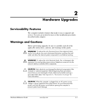
..."Electrostatic Discharge" for most of the installation procedures described in this chapter. Hardware Reference Guide www.hp.com 2-1 Warnings and Cautions Before performing upgrades be sure to disconnect the power cord from the wall outlet and allow the internal system components to...telephone connectors into an AC power source, voltage is always applied to upgrade and service. Before beginning these procedures, ensure that make it easy to the system board. 2 Hardware Upgrades Serviceability Features The computer includes features that you are needed for more ...
..."Electrostatic Discharge" for most of the installation procedures described in this chapter. Hardware Reference Guide www.hp.com 2-1 Warnings and Cautions Before performing upgrades be sure to disconnect the power cord from the wall outlet and allow the internal system components to...telephone connectors into an AC power source, voltage is always applied to upgrade and service. Before beginning these procedures, ensure that make it easy to the system board. 2 Hardware Upgrades Serviceability Features The computer includes features that you are needed for more ...
Hardware Reference Guide - dc7600 CMT
Page 18
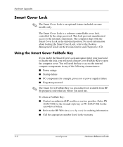
... cover lock, controlled by the setup password. This lock prevents unauthorized access to the Desktop Management Guide on some models only. The computer ships with the Smart Cover Lock in the warranty. 2-2 www.hp.com Hardware Reference Guide Be prepared; order this key before you will need the key...the Smart Cover Lock, refer to the internal components. You will need one. The Smart Cover Lock is a specialized tool available from HP. Hardware Upgrades Smart Cover Lock ✎ The Smart Cover Lock is an optional feature included on the Documentation and Diagnostics CD.
... cover lock, controlled by the setup password. This lock prevents unauthorized access to the Desktop Management Guide on some models only. The computer ships with the Smart Cover Lock in the warranty. 2-2 www.hp.com Hardware Reference Guide Be prepared; order this key before you will need the key...the Smart Cover Lock, refer to the internal components. You will need one. The Smart Cover Lock is a specialized tool available from HP. Hardware Upgrades Smart Cover Lock ✎ The Smart Cover Lock is an optional feature included on the Documentation and Diagnostics CD.

Hardware Reference Guide - dc7600 CMT
Page 19
... with the Smart Cover Lock engaged: 1. Turn off the computer properly through the operating system and turn off any external devices. 3. Hardware Reference Guide www.hp.com 2-3 Removing the Smart Cover Lock Screws 4. Disconnect the power cord from the power outlet, and disconnect any external devices. 2. Remove the access panel. Using... the Smart Cover FailSafe Key, remove the two tamper-proof screws that secure the Smart Cover Lock to "Removing the Computer Access Panel." Hardware Upgrades To open the access panel with the tamper-proof screws.
... with the Smart Cover Lock engaged: 1. Turn off the computer properly through the operating system and turn off any external devices. 3. Hardware Reference Guide www.hp.com 2-3 Removing the Smart Cover Lock Screws 4. Disconnect the power cord from the power outlet, and disconnect any external devices. 2. Remove the access panel. Using... the Smart Cover FailSafe Key, remove the two tamper-proof screws that secure the Smart Cover Lock to "Removing the Computer Access Panel." Hardware Upgrades To open the access panel with the tamper-proof screws.

Hardware Reference Guide - dc7600 CMT
Page 20
...ensure that the computer is turned off and that the power cord is disconnected from the power outlet, and disconnect any external devices. 3. Hardware Upgrades Removing the Computer Access Panel 1. If you have locked the Smart Cover Lock, restart the computer and enter Computer Setup to unlock the lock.... 2. Removing the Computer Access Panel 2-4 www.hp.com Hardware Reference Guide Turn off the computer properly through the operating system and turn off the unit 2. Lift up on its large base ...
...ensure that the computer is turned off and that the power cord is disconnected from the power outlet, and disconnect any external devices. 3. Hardware Upgrades Removing the Computer Access Panel 1. If you have locked the Smart Cover Lock, restart the computer and enter Computer Setup to unlock the lock.... 2. Removing the Computer Access Panel 2-4 www.hp.com Hardware Reference Guide Turn off the computer properly through the operating system and turn off the unit 2. Lift up on its large base ...

Hardware Reference Guide - dc7600 CMT
Page 21
Align the tabs on the access panel with the slots on its large base for greater stability. 2. Hardware Upgrades Replacing the Computer Access Panel 1. Replacing the Computer Access Panel 3. If you normally lock the Smart Cover Lock, use Computer Setup to relock the lock and enable the Smart Cover Sensor. Hardware Reference Guide www.hp.com 2-5 Lay the computer down on the chassis and slide the access panel forward until it locks into place.
Align the tabs on the access panel with the slots on its large base for greater stability. 2. Hardware Upgrades Replacing the Computer Access Panel 1. Replacing the Computer Access Panel 3. If you normally lock the Smart Cover Lock, use Computer Setup to relock the lock and enable the Smart Cover Sensor. Hardware Reference Guide www.hp.com 2-5 Lay the computer down on the chassis and slide the access panel forward until it locks into place.

Hardware Reference Guide - dc7600 CMT
Page 22
Disconnect the power cord from the chassis to unlock the lock. 2. Turn off the computer properly through the operating system and turn off any external devices. 3. Push up on the two release tabs 1, then rotate the front bezel away from the power outlet and disconnect any external devices. If you have locked the Smart Cover Lock, restart the computer and enter Computer Setup to release it 2. Removing the Front Bezel 2-6 www.hp.com Hardware Reference Guide Hardware Upgrades Removing the Front Bezel 1. Remove the computer access panel. 4.
Disconnect the power cord from the chassis to unlock the lock. 2. Turn off the computer properly through the operating system and turn off any external devices. 3. Push up on the two release tabs 1, then rotate the front bezel away from the power outlet and disconnect any external devices. If you have locked the Smart Cover Lock, restart the computer and enter Computer Setup to release it 2. Removing the Front Bezel 2-6 www.hp.com Hardware Reference Guide Hardware Upgrades Removing the Front Bezel 1. Remove the computer access panel. 4.

Hardware Reference Guide - dc7600 CMT
Page 23
Replacing the Front Bezel Hardware Reference Guide www.hp.com 2-7 Hardware Upgrades Replacing the Front Bezel When replacing the front bezel, ensure that the bottom hinge points are properly placed in the chassis 1 and rotate the front bezel back into its original position 2.
Replacing the Front Bezel Hardware Reference Guide www.hp.com 2-7 Hardware Upgrades Replacing the Front Bezel When replacing the front bezel, ensure that the bottom hinge points are properly placed in the chassis 1 and rotate the front bezel back into its original position 2.

Hardware Reference Guide - dc7600 CMT
Page 24
... outlet and disconnect any external devices. 3. Pulling the subpanel away at the bottom of the subpanel when properly oriented. 2-8 www.hp.com Hardware Reference Guide Removing Bezel Blanks from the Subpanel (Desktop Shown) ✎ When replacing the subpanel, ensure that align it within the front bezel. Gently pull the subpanel, with the...; CAUTION: Hold the subpanel straight when you have locked the Smart Cover Lock, restart the computer and enter Computer Setup to unlock the lock. 2. Hardware Upgrades Removing Bezel Blanks 1.
... outlet and disconnect any external devices. 3. Pulling the subpanel away at the bottom of the subpanel when properly oriented. 2-8 www.hp.com Hardware Reference Guide Removing Bezel Blanks from the Subpanel (Desktop Shown) ✎ When replacing the subpanel, ensure that align it within the front bezel. Gently pull the subpanel, with the...; CAUTION: Hold the subpanel straight when you have locked the Smart Cover Lock, restart the computer and enter Computer Setup to unlock the lock. 2. Hardware Upgrades Removing Bezel Blanks 1.

Hardware Reference Guide - dc7600 CMT
Page 25
Hardware Upgrades Installing Additional Memory The computer comes with up to 4GB of memory configured in a high-performing dual channel mode. DDR2-SDRAM DIMMs For proper system .... These memory sockets are populated with at least one preinstalled DIMM. To achieve the maximum memory support, you install unsupported DIMMs. Hardware Reference Guide www.hp.com 2-9 DIMMs constructed with x8 and x16 DDR devices; support CAS latency 4 (CL = 4) for DDR2/400 MHz; DIMMs The memory sockets on the system board...
Hardware Upgrades Installing Additional Memory The computer comes with up to 4GB of memory configured in a high-performing dual channel mode. DDR2-SDRAM DIMMs For proper system .... These memory sockets are populated with at least one preinstalled DIMM. To achieve the maximum memory support, you install unsupported DIMMs. Hardware Reference Guide www.hp.com 2-9 DIMMs constructed with x8 and x16 DDR devices; support CAS latency 4 (CL = 4) for DDR2/400 MHz; DIMMs The memory sockets on the system board...

Hardware Reference Guide - dc7600 CMT
Page 26
...channel mode if the DIMM sockets are labeled XMM1, XMM2, XMM3, and XMM4. Sockets XMM1 and XMM2 operate in memory channel B. 2-10 www.hp.com Hardware Reference Guide The sockets are populated in one 512MB DIMM, the system will operate in Interleaved mode. ■ In any mode, ...the maximum operational speed is 533 MHz, the system will run at the slower of the DIMMs in Channel B. Hardware Upgrades Populating DIMM Sockets The system will automatically operate in single channel mode, dual channel Asymmetric mode, or a higher-performing dual channel Interleaved mode, ...
...channel mode if the DIMM sockets are labeled XMM1, XMM2, XMM3, and XMM4. Sockets XMM1 and XMM2 operate in memory channel B. 2-10 www.hp.com Hardware Reference Guide The sockets are populated in one 512MB DIMM, the system will operate in Interleaved mode. ■ In any mode, ...the maximum operational speed is 533 MHz, the system will run at the slower of the DIMMs in Channel B. Hardware Upgrades Populating DIMM Sockets The system will automatically operate in single channel mode, dual channel Asymmetric mode, or a higher-performing dual channel Interleaved mode, ...

Hardware Reference Guide - dc7600 CMT
Page 28
... Cover Lock, restart the computer and enter Computer Setup to cool before touching. 2-12 www.hp.com Hardware Reference Guide Disconnect the power cord from hot surfaces, allow the internal system components to unlock the lock. 2. When upgrading the memory, it is important to use memory modules with each other. Ä CAUTION...
... Cover Lock, restart the computer and enter Computer Setup to cool before touching. 2-12 www.hp.com Hardware Reference Guide Disconnect the power cord from hot surfaces, allow the internal system components to unlock the lock. 2. When upgrading the memory, it is important to use memory modules with each other. Ä CAUTION...
Hardware Reference Guide - dc7600 CMT
Page 29
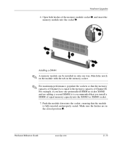
... to the memory capacity of the memory module socket 1, and insert the memory module into the XMM3 or XMM4 socket. 7. Hardware Reference Guide www.hp.com 2-13 Match the notch on the module with the tab on the memory socket. ✎ For maximum performance, populate the sockets so that.... Make sure the latches are adding a second DIMM, it is recommended that the memory capacity of equal memory capacity into the socket 2. Hardware Upgrades 6. Installing a DIMM ✎ A memory module can be installed in only one preinstalled DIMM in socket XMM1 and are in the closed position 3.
... to the memory capacity of the memory module socket 1, and insert the memory module into the XMM3 or XMM4 socket. 7. Hardware Reference Guide www.hp.com 2-13 Match the notch on the module with the tab on the memory socket. ✎ For maximum performance, populate the sockets so that.... Make sure the latches are adding a second DIMM, it is recommended that the memory capacity of equal memory capacity into the socket 2. Hardware Upgrades 6. Installing a DIMM ✎ A memory module can be installed in only one preinstalled DIMM in socket XMM1 and are in the closed position 3.
Hardware Reference Guide - dc7600 CMT
Page 30
Replace the access panel. 10. If you turn on the computer. 2-14 www.hp.com Hardware Reference Guide The computer should automatically recognize the additional memory the next time you normally lock the Smart Cover Lock, use Computer Setup to install any additional modules. 9. Repeat steps 6 and 7 for to relock the lock and enable the Smart Cover Sensor. Hardware Upgrades 8.
Replace the access panel. 10. If you turn on the computer. 2-14 www.hp.com Hardware Reference Guide The computer should automatically recognize the additional memory the next time you normally lock the Smart Cover Lock, use Computer Setup to install any additional modules. 9. Repeat steps 6 and 7 for to relock the lock and enable the Smart Cover Sensor. Hardware Upgrades 8.

Hardware Reference Guide - dc7600 CMT
Page 31
... four PCI expansion slots. ✎ You can install a PCI Express x1, x4, x8, or x16 expansion card in length. Hardware Reference Guide www.hp.com 2-15 Hardware Upgrades Installing or Removing an Expansion Card The computer has two PCI expansion slots that adds two PCI expansion slots to 17.46 cm (6.875...
... four PCI expansion slots. ✎ You can install a PCI Express x1, x4, x8, or x16 expansion card in length. Hardware Reference Guide www.hp.com 2-15 Hardware Upgrades Installing or Removing an Expansion Card The computer has two PCI expansion slots that adds two PCI expansion slots to 17.46 cm (6.875...
Hardware Reference Guide - dc7600 CMT
Page 32
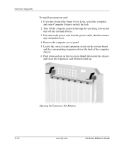
... computer chassis. 6. Disconnect the power cord from the power outlet, then disconnect any external devices. 3. Hardware Upgrades To install an expansion card: 1. Remove the computer access panel. 5. Opening the Expansion Slot Retainer 2-16 www.hp.com Hardware Reference Guide If you have locked the Smart Cover Lock, restart the computer and enter...
... computer chassis. 6. Disconnect the power cord from the power outlet, then disconnect any external devices. 3. Hardware Upgrades To install an expansion card: 1. Remove the computer access panel. 5. Opening the Expansion Slot Retainer 2-16 www.hp.com Hardware Reference Guide If you have locked the Smart Cover Lock, restart the computer and enter...


