End User License Agreement
Page 2
... EULA is automatically terminated. Any transfer must first be governed by the Microsoft License Agreement. 2. TERM. TRANSFER. This EULA will prevail. 4. entirely by HP as eligible for the upgrade. Recovery Solution. The use technical information you must include all the EULA terms. Upon transfer of this EULA. 7. You may not sublicense, assign...
... EULA is automatically terminated. Any transfer must first be governed by the Microsoft License Agreement. 2. TERM. TRANSFER. This EULA will prevail. 4. entirely by HP as eligible for the upgrade. Recovery Solution. The use technical information you must include all the EULA terms. Upon transfer of this EULA. 7. You may not sublicense, assign...

Global Limited Warranty and Technical Support
Page 5
... normally fifteen (15) days. Service Upgrades HP has a range of service upgrades and the cost for more details. The HP Option Limited Warranty Period starts from the date you . For information on the HP Web site at : http://www.hp.com/support. Non-HP options are as defined below) OR THE...BY APPLICABLE LAW, IN NO EVENT SHALL HP OR ITS SUPPLIERS BE LIABLE FOR ANY SPECIAL, INCIDENTAL, INDIRECT, OR CONSEQUENTIAL DAMAGES WHATSOEVER (INCLUDING, BUT NOT LIMITED TO, DAMAGES FOR LOSS OF PROFITS OR CONFIDENTIAL OR OTHER INFORMATION, FOR BUSINESS INTERRUPTION, FOR PERSONAL INJURY, FOR LOSS OF...
... normally fifteen (15) days. Service Upgrades HP has a range of service upgrades and the cost for more details. The HP Option Limited Warranty Period starts from the date you . For information on the HP Web site at : http://www.hp.com/support. Non-HP options are as defined below) OR THE...BY APPLICABLE LAW, IN NO EVENT SHALL HP OR ITS SUPPLIERS BE LIABLE FOR ANY SPECIAL, INCIDENTAL, INDIRECT, OR CONSEQUENTIAL DAMAGES WHATSOEVER (INCLUDING, BUT NOT LIMITED TO, DAMAGES FOR LOSS OF PROFITS OR CONFIDENTIAL OR OTHER INFORMATION, FOR BUSINESS INTERRUPTION, FOR PERSONAL INJURY, FOR LOSS OF...

Global Limited Warranty and Technical Support
Page 5
.... If the removable media on the duration of the HP Hardware Product in which HP distributes the software proves to be purchased locally. Service Upgrades HP has a range of additional support and service coverage for most HP-branded options (HP Options) are set forth in all countries. However, ...BY APPLICABLE LAW, IN NO EVENT SHALL HP OR ITS SUPPLIERS BE LIABLE FOR ANY SPECIAL, INCIDENTAL, INDIRECT, OR CONSEQUENTIAL DAMAGES WHATSOEVER (INCLUDING, BUT NOT LIMITED TO, DAMAGES FOR LOSS OF PROFITS OR CONFIDENTIAL OR OTHER INFORMATION, FOR BUSINESS INTERRUPTION, FOR PERSONAL INJURY, FOR LOSS...
.... If the removable media on the duration of the HP Hardware Product in which HP distributes the software proves to be purchased locally. Service Upgrades HP has a range of additional support and service coverage for most HP-branded options (HP Options) are set forth in all countries. However, ...BY APPLICABLE LAW, IN NO EVENT SHALL HP OR ITS SUPPLIERS BE LIABLE FOR ANY SPECIAL, INCIDENTAL, INDIRECT, OR CONSEQUENTIAL DAMAGES WHATSOEVER (INCLUDING, BUT NOT LIMITED TO, DAMAGES FOR LOSS OF PROFITS OR CONFIDENTIAL OR OTHER INFORMATION, FOR BUSINESS INTERRUPTION, FOR PERSONAL INJURY, FOR LOSS...
Hardware Reference Guide - dc7600 CMT
Page 1
Hardware Reference Guide HP Compaq Business PC dc7600 Convertible Minitower Document Part Number: 384568-001 May 2005 This guide provides basic information for upgrading this computer model.
Hardware Reference Guide HP Compaq Business PC dc7600 Convertible Minitower Document Part Number: 384568-001 May 2005 This guide provides basic information for upgrading this computer model.

Hardware Reference Guide - dc7600 CMT
Page 3
... Panel Components 1-3 Keyboard 1-4 Using the Windows Logo Key 1-5 Special Mouse Functions 1-5 Serial Number Location 1-6 Changing from a Minitower to a Desktop Configuration 1-7 Changing from a Desktop to a Minitower Configuration 1-10 2 Hardware Upgrades Serviceability Features 2-1 Warnings and Cautions 2-1 Smart Cover Lock 2-2 Using the Smart Cover FailSafe Key 2-2 Removing the Computer Access Panel 2-4 Replacing... Installing DIMMs 2-12 Installing or Removing an Expansion Card 2-15 Drive Positions 2-21 Installing Additional Drives 2-22 Hardware Reference Guide www.hp.com iii
... Panel Components 1-3 Keyboard 1-4 Using the Windows Logo Key 1-5 Special Mouse Functions 1-5 Serial Number Location 1-6 Changing from a Minitower to a Desktop Configuration 1-7 Changing from a Desktop to a Minitower Configuration 1-10 2 Hardware Upgrades Serviceability Features 2-1 Warnings and Cautions 2-1 Smart Cover Lock 2-2 Using the Smart Cover FailSafe Key 2-2 Removing the Computer Access Panel 2-4 Replacing... Installing DIMMs 2-12 Installing or Removing an Expansion Card 2-15 Drive Positions 2-21 Installing Additional Drives 2-22 Hardware Reference Guide www.hp.com iii
Hardware Reference Guide - dc7600 CMT
Page 17
...not plug telecommunications/telephone connectors into an AC power source, voltage is always applied to the system board. Hardware Reference Guide www.hp.com 2-1 See Appendix D, "Electrostatic Discharge" for most of the installation procedures described in this chapter. No tools are discharged ... the power cord from the wall outlet and allow the internal system components to cool before opening the computer to upgrade and service. 2 Hardware Upgrades Serviceability Features The computer includes features that you are needed for more information. Ä CAUTION: When the computer ...
...not plug telecommunications/telephone connectors into an AC power source, voltage is always applied to the system board. Hardware Reference Guide www.hp.com 2-1 See Appendix D, "Electrostatic Discharge" for most of the installation procedures described in this chapter. No tools are discharged ... the power cord from the wall outlet and allow the internal system components to cool before opening the computer to upgrade and service. 2 Hardware Upgrades Serviceability Features The computer includes features that you are needed for more information. Ä CAUTION: When the computer ...
Hardware Reference Guide - dc7600 CMT
Page 18
...will need a Smart Cover FailSafe Key to open the computer cover. For more information about locking the Smart Cover Lock, refer to the HP Web site (www.hp.com) for example, processor or power supply) failure ■ Forgotten password ✎ The Smart Cover FailSafe Key is a specialized tool ...key. ■ Refer to the Desktop Management Guide on some models only. Using the Smart Cover FailSafe Key If you enable the Smart Cover Lock and cannot enter your password to disable the lock, you need the key to the internal components. Hardware Upgrades Smart Cover Lock ✎ The...
...will need a Smart Cover FailSafe Key to open the computer cover. For more information about locking the Smart Cover Lock, refer to the HP Web site (www.hp.com) for example, processor or power supply) failure ■ Forgotten password ✎ The Smart Cover FailSafe Key is a specialized tool ...key. ■ Refer to the Desktop Management Guide on some models only. Using the Smart Cover FailSafe Key If you enable the Smart Cover Lock and cannot enter your password to disable the lock, you need the key to the internal components. Hardware Upgrades Smart Cover Lock ✎ The...

Hardware Reference Guide - dc7600 CMT
Page 19
... "Removing the Computer Access Panel." Turn off the computer properly through the operating system and turn off any external devices. 3. Hardware Reference Guide www.hp.com 2-3 Hardware Upgrades To open the access panel with the tamper-proof screws. To reattach the Smart Cover Lock, secure the lock in place with the Smart...
... "Removing the Computer Access Panel." Turn off the computer properly through the operating system and turn off any external devices. 3. Hardware Reference Guide www.hp.com 2-3 Hardware Upgrades To open the access panel with the tamper-proof screws. To reattach the Smart Cover Lock, secure the lock in place with the Smart...

Hardware Reference Guide - dc7600 CMT
Page 20
Lift up on its large base for greater stability. 5. Hardware Upgrades Removing the Computer Access Panel 1. Lay the computer down on the access panel handle 1, slide the access panel back about 2.5 cm (1 inch), then lift it ...up and off and that the power cord is disconnected from the power outlet, and disconnect any external devices. 3. Removing the Computer Access Panel 2-4 www.hp.com Hardware Reference Guide If you have locked the Smart Cover Lock, restart the computer and enter Computer Setup to unlock the lock. 2. Disconnect the...
Lift up on its large base for greater stability. 5. Hardware Upgrades Removing the Computer Access Panel 1. Lay the computer down on the access panel handle 1, slide the access panel back about 2.5 cm (1 inch), then lift it ...up and off and that the power cord is disconnected from the power outlet, and disconnect any external devices. 3. Removing the Computer Access Panel 2-4 www.hp.com Hardware Reference Guide If you have locked the Smart Cover Lock, restart the computer and enter Computer Setup to unlock the lock. 2. Disconnect the...

Hardware Reference Guide - dc7600 CMT
Page 21
Align the tabs on the access panel with the slots on its large base for greater stability. 2. Replacing the Computer Access Panel 3. If you normally lock the Smart Cover Lock, use Computer Setup to relock the lock and enable the Smart Cover Sensor. Lay the computer down on the chassis and slide the access panel forward until it locks into place. Hardware Reference Guide www.hp.com 2-5 Hardware Upgrades Replacing the Computer Access Panel 1.
Align the tabs on the access panel with the slots on its large base for greater stability. 2. Replacing the Computer Access Panel 3. If you normally lock the Smart Cover Lock, use Computer Setup to relock the lock and enable the Smart Cover Sensor. Lay the computer down on the chassis and slide the access panel forward until it locks into place. Hardware Reference Guide www.hp.com 2-5 Hardware Upgrades Replacing the Computer Access Panel 1.

Hardware Reference Guide - dc7600 CMT
Page 22
Turn off the computer properly through the operating system and turn off any external devices. 3. Remove the computer access panel. 4. Removing the Front Bezel 2-6 www.hp.com Hardware Reference Guide Hardware Upgrades Removing the Front Bezel 1. Push up on the two release tabs 1, then rotate the front bezel away from the power outlet and disconnect any external devices. If you have locked the Smart Cover Lock, restart the computer and enter Computer Setup to release it 2. Disconnect the power cord from the chassis to unlock the lock. 2.
Turn off the computer properly through the operating system and turn off any external devices. 3. Remove the computer access panel. 4. Removing the Front Bezel 2-6 www.hp.com Hardware Reference Guide Hardware Upgrades Removing the Front Bezel 1. Push up on the two release tabs 1, then rotate the front bezel away from the power outlet and disconnect any external devices. If you have locked the Smart Cover Lock, restart the computer and enter Computer Setup to release it 2. Disconnect the power cord from the chassis to unlock the lock. 2.

Hardware Reference Guide - dc7600 CMT
Page 23
Hardware Upgrades Replacing the Front Bezel When replacing the front bezel, ensure that the bottom hinge points are properly placed in the chassis 1 and rotate the front bezel back into its original position 2. Replacing the Front Bezel Hardware Reference Guide www.hp.com 2-7
Hardware Upgrades Replacing the Front Bezel When replacing the front bezel, ensure that the bottom hinge points are properly placed in the chassis 1 and rotate the front bezel back into its original position 2. Replacing the Front Bezel Hardware Reference Guide www.hp.com 2-7

Hardware Reference Guide - dc7600 CMT
Page 24
Removing Bezel Blanks from the Subpanel (Desktop Shown) ✎ When replacing the subpanel, ensure that align it away from the power outlet and disconnect any external devices. Disconnect the power cord from ... Smart Cover Lock, restart the computer and enter Computer Setup to unlock the lock. 2. Remove the computer access panel then remove the front bezel. 4. Hardware Upgrades Removing Bezel Blanks 1. Turn off the computer properly through the operating system and turn off any external devices. 3. Pulling the subpanel away at the bottom...
Removing Bezel Blanks from the Subpanel (Desktop Shown) ✎ When replacing the subpanel, ensure that align it away from the power outlet and disconnect any external devices. Disconnect the power cord from ... Smart Cover Lock, restart the computer and enter Computer Setup to unlock the lock. 2. Remove the computer access panel then remove the front bezel. 4. Hardware Upgrades Removing Bezel Blanks 1. Turn off the computer properly through the operating system and turn off any external devices. 3. Pulling the subpanel away at the bottom...

Hardware Reference Guide - dc7600 CMT
Page 25
...double-sided DIMMS ■ DIMMs constructed with x8 and x16 DDR devices; support CAS latency 4 (CL = 4) for DDR2/400 MHz; Hardware Upgrades Installing Additional Memory The computer comes with up to 4GB of memory configured in a high-performing dual channel mode. DDR2-SDRAM DIMMs For proper ... DIMMs. These memory sockets are not supported ✎ The system will not start if you install unsupported DIMMs. Hardware Reference Guide www.hp.com 2-9 DIMMs The memory sockets on the system board can populate the system board with double data rate 2 synchronous dynamic random access ...
...double-sided DIMMS ■ DIMMs constructed with x8 and x16 DDR devices; support CAS latency 4 (CL = 4) for DDR2/400 MHz; Hardware Upgrades Installing Additional Memory The computer comes with up to 4GB of memory configured in a high-performing dual channel mode. DDR2-SDRAM DIMMs For proper ... DIMMs. These memory sockets are not supported ✎ The system will not start if you install unsupported DIMMs. Hardware Reference Guide www.hp.com 2-9 DIMMs The memory sockets on the system board can populate the system board with double data rate 2 synchronous dynamic random access ...

Hardware Reference Guide - dc7600 CMT
Page 26
... mode if the DIMM sockets are labeled XMM1, XMM2, XMM3, and XMM4. Sockets XMM1 and XMM2 operate in memory channel B. 2-10 www.hp.com Hardware Reference Guide Hardware Upgrades Populating DIMM Sockets The system will automatically operate in single channel mode, dual channel Asymmetric mode, or a higher-performing dual channel Interleaved mode...
... mode if the DIMM sockets are labeled XMM1, XMM2, XMM3, and XMM4. Sockets XMM1 and XMM2 operate in memory channel B. 2-10 www.hp.com Hardware Reference Guide Hardware Upgrades Populating DIMM Sockets The system will automatically operate in single channel mode, dual channel Asymmetric mode, or a higher-performing dual channel Interleaved mode...

Hardware Reference Guide - dc7600 CMT
Page 28
...module sockets on the system board. Å WARNING: To reduce risk of the computer or optional cards. Hardware Upgrades Installing DIMMs Ä CAUTION: The memory module sockets have locked the Smart Cover Lock, restart the computer and... enter Computer Setup to unlock the lock. 2. When upgrading the memory, it is important to use memory modules with each other. Ä CAUTION: Static electricity can damage... CAUTION: When handling a memory module, be careful not to cool before touching. 2-12 www.hp.com Hardware Reference Guide
...module sockets on the system board. Å WARNING: To reduce risk of the computer or optional cards. Hardware Upgrades Installing DIMMs Ä CAUTION: The memory module sockets have locked the Smart Cover Lock, restart the computer and... enter Computer Setup to unlock the lock. 2. When upgrading the memory, it is important to use memory modules with each other. Ä CAUTION: Static electricity can damage... CAUTION: When handling a memory module, be careful not to cool before touching. 2-12 www.hp.com Hardware Reference Guide
Hardware Reference Guide - dc7600 CMT
Page 29
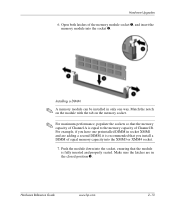
... socket. ✎ For maximum performance, populate the sockets so that the memory capacity of Channel A is fully inserted and properly seated. Hardware Reference Guide www.hp.com 2-13 Hardware Upgrades 6. Installing a DIMM ✎ A memory module can be installed in only one preinstalled DIMM in the closed position 3. Open both latches of Channel B.
... socket. ✎ For maximum performance, populate the sockets so that the memory capacity of Channel A is fully inserted and properly seated. Hardware Reference Guide www.hp.com 2-13 Hardware Upgrades 6. Installing a DIMM ✎ A memory module can be installed in only one preinstalled DIMM in the closed position 3. Open both latches of Channel B.
Hardware Reference Guide - dc7600 CMT
Page 30
Replace the access panel. 10. If you turn on the computer. 2-14 www.hp.com Hardware Reference Guide The computer should automatically recognize the additional memory the next time you normally lock the Smart Cover Lock, use Computer Setup to install any additional modules. 9. Hardware Upgrades 8. Repeat steps 6 and 7 for to relock the lock and enable the Smart Cover Sensor.
Replace the access panel. 10. If you turn on the computer. 2-14 www.hp.com Hardware Reference Guide The computer should automatically recognize the additional memory the next time you normally lock the Smart Cover Lock, use Computer Setup to install any additional modules. 9. Hardware Upgrades 8. Repeat steps 6 and 7 for to relock the lock and enable the Smart Cover Sensor.

Hardware Reference Guide - dc7600 CMT
Page 31
Hardware Upgrades Installing or Removing an Expansion Card The computer has two PCI expansion slots that adds two PCI expansion slots to the board for a total of ... expansion card in length. The computer also has one PCI Express x1 expansion slot and one PCI Express x16 expansion slot. Hardware Reference Guide www.hp.com 2-15
Hardware Upgrades Installing or Removing an Expansion Card The computer has two PCI expansion slots that adds two PCI expansion slots to the board for a total of ... expansion card in length. The computer also has one PCI Express x1 expansion slot and one PCI Express x16 expansion slot. Hardware Reference Guide www.hp.com 2-15
Hardware Reference Guide - dc7600 CMT
Page 32
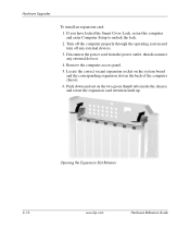
.... 5. Disconnect the power cord from the power outlet, then disconnect any external devices. 3. Push down and out on the back of the computer chassis. 6. Hardware Upgrades To install an expansion card: 1. Opening the Expansion Slot Retainer 2-16 www...
.... 5. Disconnect the power cord from the power outlet, then disconnect any external devices. 3. Push down and out on the back of the computer chassis. 6. Hardware Upgrades To install an expansion card: 1. Opening the Expansion Slot Retainer 2-16 www...


