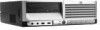
Safety and Regulatory Information Desktops, Thin Clients, and Personal Workstations
Page 29
... Substances and Elements (continued) Part Name Lead (Pb) Mercury (Hg) Cadmium (Cd) Hexavalent Chromium (Cr(VI)) Memory X O O O I/O PCAs X O O O Power supply X O O O Keyboard X O O O Mouse X O O O Chassis/Other X O O O Fans X O O O Internal/External Media Reading X O O O Devices External Control Devices X O O O Cable X O O O Hard Disk Drive X O O O Display X X O O Polybrominated biphenyls (PBB) Polybrominated diphenyl ethers (PBDE) O O O O O O O O O O O O O O O O O O O O O O O O O: Indicates that...
HP Compaq Business Desktop dc7100 Series Service Reference Guide, 3rd Edition
Page 5
... the Mouse 5-7 5.5 Service Considerations 5-8 5.5.1 Power Supply Fan 5-8 5.5.2 Tools and Software Requirements 5-8 5.5.3 Screws 5-8 5.5.4 Cables and Connectors 5-9 5.5.5 Hard Drives 5-9 5.5.6 Lithium Coin Cell Battery 5-9 6 Removal and Replacement Procedures - Convertible Minitower (CMT) Chassis 6.1 Preparation for Disassembly 6-1 6.2 Unlocking the Smart Cover ...34 6.19Processor 6-35 6.20Speaker 6-37 6.21Chassis Fan 6-38 6.22Power Supply 6-39 6.23Changing from Desktop to Minitower 6-40 6.24Changing from Minitower to Desktop 6-43 Service Reference Guide, dc7100 361288-003 v
HP Compaq Business Desktop dc7100 Series Service Reference Guide, 3rd Edition
Page 6
... 8-5 vi 361288-003 Service Reference Guide, dc7100 Ultra-Slim Desktop (USDT) Chassis 8.1 Preparation for Disassembly 7-1 7.2 Unlocking the Smart Cover Lock 7-2 7.3 Hood Sensor 7-4 7.4 External Security Devices 7-5 7.4.1 Security Clip 7-5 7.4.2 Cable Lock 7-5 7.4.3 Padlock 7-6 7.4.4 Universal Chassis Clamp Lock 7-6 7.5 Computer Cover 7-11 ...Assembly 7-39 7.15Heatsink 7-40 7.16Processor 7-41 7.17Speaker 7-43 7.18Power Supply 7-44 7.19System Board 7-46 7.20Chassis Fan 7-50 7.21Backwall 7-51 7.22Battery 7-58 7.22.1Type 1 Battery Holder 7-59 7.22.2Type 2 Battery Holder 7-...
HP Compaq Business Desktop dc7100 Series Service Reference Guide, 3rd Edition
Page 7
... 8-7 8.6 Front Panel Assembly 8-8 8.7 Front Bezel 8-9 8.8 Chassis Fan 8-10 8.9 Cable Management 8-11 8.10Memory 8-12 8.11Expansion Card Cage 8-14 8.12Expansion Card 8-15 8.13Hood Sensor 8-17 8.14Expansion Card Retaining Latch 8-18 8.15Hard Drive 8-19 8.16Front I/O Device 8-21 8.17Heatsink Assembly 8-22 8.17.1Heatsink Fan with Shroud 8-23 8.18Processor 8-24 8.19Power Supply 8-26 8....Cord Set Requirements C POST Error Messages D Troubleshooting Without Diagnostics E System Board and Riser Card Reference Designators F Memory Index Service Reference Guide, dc7100 361288-003 vii
HP Compaq Business Desktop dc7100 Series Service Reference Guide, 3rd Edition
Page 78
...HP strongly recommends that all screws removed during the disassembly and assembly of the computer. 5.5.1 Power Supply Fan The power supply fan is a variable-speed fan based on the temperature in the power supply. Ä CAUTION: The cooling fan...9632; Phillips #2 screwdriver ■ Diagnostics software ■ Compaq tamper-resistant T-15 wrench (Smart Cover FailSafe Key, PN 166527-001) or Compaq tamper-resistant bits (Smart Cover FailSafe Key, PN 166527-002..., dc7100 Identifying the Chassis, Routine Care, and Disassembly Preparation 5.5 Service Considerations Listed below are not...
HP Compaq Business Desktop dc7100 Series Service Reference Guide, 3rd Edition
Page 81
...Chassis Adherence to verify that all components operate properly. ✎ Not all features listed in this guide are available on even when the computer is plugged into an active AC outlet. Disconnect the power cord from the electrical outlet and then from the computer. 5. Service Reference Guide, dc7100...disc, or MultiBay device from the computer. 7. In some systems the cooling fan is on all computers. 6.1 Preparation for Disassembly See Chapter 5, 'Identifying the Chassis, Routine Care, and Disassembly Preparation' for proper service. Remove any security devices...
HP Compaq Business Desktop dc7100 Series Service Reference Guide, 3rd Edition
Page 118
Remove the computer access panel (Section 6.5). 3. Prepare the computer for disassembly (Section 6.1). 2. To install the fan assembly, reverse the removal procedure. 6-38 361288-003 Service Reference Guide, dc7100 Disconnect the fan control cable from the system board. 4. Remove the four screws that secure the fan assembly to the chassis 1 and then remove the fan assembly 2. Removal and Replacement Procedures - Convertible Minitower (CMT) Chassis 6.21 Chassis Fan 1.
HP Compaq Business Desktop dc7100 Series Service Reference Guide, 3rd Edition
Page 127
... as long as you remove it . Ä CAUTION: Turn off the computer before servicing a unit. 6. Service Reference Guide, dc7100 361288-003 7-1 Remove/disengage any peripheral devices that are available on even when the computer is in this chapter is plugged into an...computer. 7. Keep all computers. 7.1 Preparation for Disassembly See Chapter 5, "Identifying the Chassis, Routine Care, and Disassembly Preparation" for proper service. 7 Removal and Replacement Procedures- In some systems the cooling fan is on all screws with the units removed. Ä CAUTION: The screws used in...
HP Compaq Business Desktop dc7100 Series Service Reference Guide, 3rd Edition
Page 160
Small Form Factor (SFF) Chassis 7.12 Fan Shroud 1. Lift up on the fan shroud to remove it does not get caught on the wires from the computer. Removal and Replacement Procedures- When replacing the shroud, make sure that it from either the fan or the speaker. 7-34 361288-003 Service Reference Guide, dc7100 Prepare the computer for disassembly (Section 7.1, "Preparation for Disassembly"). 2. Remove the computer cover (Section 7.5, "Computer Cover"). 3.
HP Compaq Business Desktop dc7100 Series Service Reference Guide, 3rd Edition
Page 176
Small Form Factor (SFF) Chassis 7.20 Chassis Fan 1. Remove the computer cover (Section 7.5, "Computer Cover"). 3. Disconnect the chassis fan cable from the chassis. . Remove the four screws that secure the fan and fan guard to the chassis then, remove the fan from the system board. 5. Prepare the computer for disassembly (Section 7.1, "Preparation for Disassembly"). 2. To install the chassis fan, reverse the removal procedure. 7-50 361288-003 Service Reference Guide, dc7100 Remove the fan shroud (Section 7.12, "Fan Shroud"). 4. Removal and Replacement Procedures-
HP Compaq Business Desktop dc7100 Series Service Reference Guide, 3rd Edition
Page 198
... front panel assembly (Section 8.6) 6. Pull the four push pins that the fan cable is necessary to seat properly. 8-10 361288-003 Service Reference Guide, dc7100 Ultra-Slim Desktop (USDT) Chassis 8.8 Chassis Fan 1. To install the fan assembly, reverse the removal procedures, making sure that secure the fan to the front panel assembly out of the front panel assembly...
HP Compaq Business Desktop dc7100 Series Service Reference Guide, 3rd Edition
Page 235
... diskette drive. Recommended Action Reconnect keyboard with computer turned off . Replace the graphics controller (if applicable). Reseat chassis, rear chassis, or front chassis fan. Replace CPU or chassis fan. Run Computer Setup (F10 Setup). Service Reference Guide, dc7100 361288-003 C-3 Ensure that none of the keys are depressed. Ensure that none of ROMPaq to restore image. Replace...
HP Compaq Business Desktop dc7100 Series Service Reference Guide, 3rd Edition
Page 278
... header Main Power/HDD LED connector Speaker connector Analog audio connector (from CD-ROM) Primary chassis fan connector Secondary chassis fan connector Diskette drive connector Auxiliary Audio connector Alert on LAN NIC connector VRM module footprint AUI connector Fan command/fan sink header (may be 2 or 4 pin) Primary IDE connector Secondary IDE/MultiBay connector Header for...
HP Compaq Business Desktop dc7100 Series Service Reference Guide, 3rd Edition
Page 279
... for fansink Security board connector, system board Secondary speaker header Hood lock header Hood sensor header Flying parallel port header White box chassis fan header Security hood switch on riser card Clear CMOS switch/push button Single chip solution (combined north bridge/south bridge) North bridge South bridge ...Super I/O Clock chip 64 bit Bridge LOM1 LOM1 EEPROM LOM1 PHY Audio Codec Audio amplifier LOM2 LOM2 EEPROM LOM2 PHY Fan controller TMDS controller Parallel port diode array First serial port transceiver Second serial port transceiver Service Reference Guide...
HP Compaq Business Desktop dc7100 Series Service Reference Guide, 3rd Edition
Page 285
... devices 1-1 batteries 5-9 cables 5-9 cooling fan 5-8 keyboard cleaning 5-7 keyboard keys 5-7 operating system installation 1-1 protecting ROM 3-4 chassis CMT illustrated 5-1 SFF illustrated 5-2 chassis fan CMT removal and replacement 6-38 SFF removal and replacement 7-50 chassis types, illustrated 5-1 cleaning computer 5-6 keyboard... removal and replacement 6-9 cable lock removal and replacement 6-4 cable management 6-10 chassis fan removal and replacement 6-38 chassis, illustrated 5-1 desktop to minitower conversion 6-40 disassembly preparation 6-1 diskette drive bezel removal and replacement ...
HP Compaq Business Desktop dc7100 Series Service Reference Guide, 3rd Edition
Page 288
... to C-6 power cord set requirements country specific B-2 general B-1 power supply CMT removal and replacement 6-39 fan 5-8 SFF removal and replacement 7-44 USDT removal and replacement 8-26 power switch assembly CMT removal and replacement... drive bezel 6-8 CMT access panel 6-6 CMT battery 6-31 CMT bezel blank 6-9 CMT cable lock 6-4 CMT chassis fan 6-38 CMT diskette drive 6-27 CMT diskette drive bezel 6-9 CMT expansion card 6-14 CMT expansion card guide... 7-58 SFF cable lock 7-5 SFF chassis fan 7-50 SFF computer cover 7-11 SFF expansion card 7-19 Index-4 361288-003 Service Reference Guide...
HP Compaq Business Desktop dc7100 Series Service Reference Guide, 3rd Edition
Page 289
...assignments A-3 service considerations 5-8 setup software 1-2 windows 1-1 SFF battery removal and replacement 7-58 cable lock removal and replacement 7-5 cable management 7-14 chassis fan removal and replacement 7-50 chassis, illustrated 5-2 computer cover removal and replacement 7-11 disassembly preparation 7-1 drive bezel inserts 7-13 drive positions 7-26 expansion card cage removal and replacement ...and replacement 7-44 power switch assembly removal and replacement 7-39 preparation for disassembly 7-1 processor removal and replacement 7-41 Service Reference Guide, dc7100 361288-003 Index-5
Troubleshooting Guide
Page 69
... www.hp.com A-7 POST Error Messages Numeric Codes and Text Messages (Continued) Code/Message Probable Cause Recommended Action 512-Chassis, Rear Chassis, or Front Chassis Fan not Detected Chassis, rear chassis, or front chassis fan is not connected or may have malfunctioned. 1. Replace chassis, rear chassis, or front chassis fan. 514-CPU or Chassis Fan not Detected CPU or chassis fan is an issue. Reseat CPU or chassis fan...
Troubleshooting Guide
Page 68
... Chassis, or Front Chassis Fan not Detected Chassis, rear chassis, or front chassis fan is not connected or may have malfunctioned. 1. Replace chassis, rear chassis, or front chassis fan. Remove any parallel port expansion cards. 2. Reseat fan cable. 3. Clear CMOS. (See Appendix B, "Password Security and Resetting CMOS.") 3. image. 511-CPU, CPUA, or CPUB Fan not Detected CPU fan is attached and turned on. 4. A-6 www.hp...
Troubleshooting Guide
Page 69
Replace CPU or chassis fan. 601-Diskette Controller Error Diskette controller circuitry or floppy drive circuitry incorrect. 1. Check...Numeric Codes and Text Messages (Continued) Code/Message Probable Cause Recommended Action 514-CPU or Chassis Fan not Detected CPU or chassis fan is an issue. 912-Computer Cover Has Been Removed Since Last System Startup Computer cover ...cache is not working properly and will be disabled. Reseat fan cable. 3. Reseat CPU or chassis fan. 2. Clear CMOS. (See Appendix B, "Password Security and Resetting CMOS.") 4. Troubleshooting Guide www...