User Guide
Page 2
... and is a trademark of purchase. Software terms By installing, copying, downloading, or otherwise using any further information or to be construed as constituting an additional warranty. Intel is used under license. © Copyright 2015 Hewlett-Packard Development Company, L.P. First Edition: May 2015 Document Part Number: 826302-001 Product notice This guide describes features that are set forth in the U.S.
... and is a trademark of purchase. Software terms By installing, copying, downloading, or otherwise using any further information or to be construed as constituting an additional warranty. Intel is used under license. © Copyright 2015 Hewlett-Packard Development Company, L.P. First Edition: May 2015 Document Part Number: 826302-001 Product notice This guide describes features that are set forth in the U.S.
User Guide
Page 9
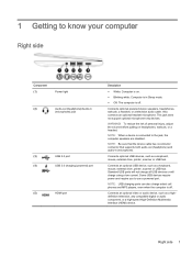
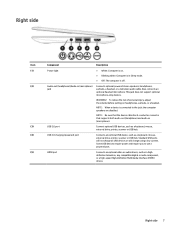
... (1) Power light (2) Audio-out (headphone)/Audio-in (microphone) jack (3) USB 2.0 port (4) USB 3.0 charging (powered) port (5) HDMI port Description ● White: Computer is on headphones, earbuds, or a headset. Connects optional powered stereo speakers, headphones, earbuds, a headset, or a television audio cable. Also connects an optional headset microphone. Standard USB ports will not charge all USB devices or will charge using a low current. NOTE: Be sure that the device cable has 4-conductor connector that supports both audio-out (headphone) and audio-in Sleep mode. ●...
... (1) Power light (2) Audio-out (headphone)/Audio-in (microphone) jack (3) USB 2.0 port (4) USB 3.0 charging (powered) port (5) HDMI port Description ● White: Computer is on headphones, earbuds, or a headset. Connects optional powered stereo speakers, headphones, earbuds, a headset, or a television audio cable. Also connects an optional headset microphone. Standard USB ports will not charge all USB devices or will charge using a low current. NOTE: Be sure that the device cable has 4-conductor connector that supports both audio-out (headphone) and audio-in Sleep mode. ●...
User Guide
Page 10
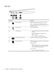
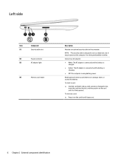
... computer Reads optional memory cards that store, manage, share, or access information. Supports a wireless subscriber identity module (SIM). Left side Component (1) Security cable slot (2) Power connector (3) AC adapter light (4) SIM slot (select models only) (5) Memory card reader Description Attaches an optional security cable to act as a deterrent, but it may not prevent the computer from being mishandled or stolen. Connects an AC adapter. ● White: The AC adapter is connected and the battery is charged. ●...
... computer Reads optional memory cards that store, manage, share, or access information. Supports a wireless subscriber identity module (SIM). Left side Component (1) Security cable slot (2) Power connector (3) AC adapter light (4) SIM slot (select models only) (5) Memory card reader Description Attaches an optional security cable to act as a deterrent, but it may not prevent the computer from being mishandled or stolen. Connects an AC adapter. ● White: The AC adapter is connected and the battery is charged. ●...
User Guide
Page 20
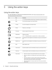
... , press and hold down the key. Volume up Increases the screen brightness incrementally as long as you hold the power button. 12 Chapter 3 Using the action keys Icon Key Description esc esc is a key that interacts with ctrl takes a screenshot. NOTE: Pressing this button in full-screen mode. 3 Using the action keys Using the action keys For more information on action keys and keyboard shortcuts, go to activate the computer's functions.
... , press and hold down the key. Volume up Increases the screen brightness incrementally as long as you hold the power button. 12 Chapter 3 Using the action keys Icon Key Description esc esc is a key that interacts with ctrl takes a screenshot. NOTE: Pressing this button in full-screen mode. 3 Using the action keys Using the action keys For more information on action keys and keyboard shortcuts, go to activate the computer's functions.
User Guide
Page 22
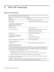
... Setup Instructions ● Overview of your warranty, please include your product number, warranty period (found on the computer and locate this computer. Safety & Comfort Guide Go to turn on your language, go to information and troubleshooting tips. IMPORTANT: Do NOT return your product located with an HP technician. ● Email support. ● Find support telephone numbers. ● Locate HP service center locations. ● Important regulatory notices. support...
... Setup Instructions ● Overview of your warranty, please include your product number, warranty period (found on the computer and locate this computer. Safety & Comfort Guide Go to turn on your language, go to information and troubleshooting tips. IMPORTANT: Do NOT return your product located with an HP technician. ● Email support. ● Find support telephone numbers. ● Locate HP service center locations. ● Important regulatory notices. support...
User Guide
Page 24
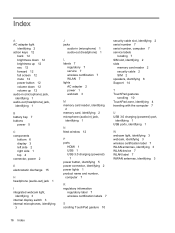
...internal display switch 3 internal microphones, identifying 3 J jacks audio-in (microphone) 1 audio-out (headphone) 1 L labels 7 regulatory 7 service 7 wireless certification 7 WLAN 7 lights AC adapter 2 power 1 webcam 3 M memory card reader, identifying 2 memory card, identifying 2 microphone (audio-in) jack, identifying 1 N Next window 12 P ports HDMI 1 USB 1 USB 3.0 charging (powered) 1 power button, identifying 5 power connector, identifying 2 power lights 1 product name and number, computer 7 R regulatory information regulatory label 7 wireless certification labels 7 S scrolling TouchPad...
...internal display switch 3 internal microphones, identifying 3 J jacks audio-in (microphone) 1 audio-out (headphone) 1 L labels 7 regulatory 7 service 7 wireless certification 7 WLAN 7 lights AC adapter 2 power 1 webcam 3 M memory card reader, identifying 2 memory card, identifying 2 microphone (audio-in) jack, identifying 1 N Next window 12 P ports HDMI 1 USB 1 USB 3.0 charging (powered) 1 power button, identifying 5 power connector, identifying 2 power lights 1 product name and number, computer 7 R regulatory information regulatory label 7 wireless certification labels 7 S scrolling TouchPad...
Maintenance and Service Guide
Page 2
....com details. See for technical or editorial errors or omissions contained herein. Some features may require upgraded and/or separately purchased hardware, drivers, and/or software to take full advantage of Windows 8. Nothing herein should be construed as constituting an additional warranty. and other countries. © Copyright 2015 Hewlett-Packard Development Company, L.P. Bluetooth is subject to most models.
....com details. See for technical or editorial errors or omissions contained herein. Some features may require upgraded and/or separately purchased hardware, drivers, and/or software to take full advantage of Windows 8. Nothing herein should be construed as constituting an additional warranty. and other countries. © Copyright 2015 Hewlett-Packard Development Company, L.P. Bluetooth is subject to most models.
Maintenance and Service Guide
Page 5
Table of contents 1 Product description ...1 2 External component identification ...3 Display ...3 Button ...4 TouchPad ...5 Left side ...6 Right side ...7 Bottom ...8 3 Illustrated parts catalog ...9 Locating the serial number, model number, product number, and warranty information 9 Computer major components ...10 Display assembly subcomponents ...12 Miscellaneous parts ...14 4 Removal and replacement preliminary requirements 15 Tools required ...15 Service considerations ...15 Plastic parts ...15 Cables and connectors ...15 Drive handling ...16 Grounding guidelines ...17 Electrostatic ...
Table of contents 1 Product description ...1 2 External component identification ...3 Display ...3 Button ...4 TouchPad ...5 Left side ...6 Right side ...7 Bottom ...8 3 Illustrated parts catalog ...9 Locating the serial number, model number, product number, and warranty information 9 Computer major components ...10 Display assembly subcomponents ...12 Miscellaneous parts ...14 4 Removal and replacement preliminary requirements 15 Tools required ...15 Service considerations ...15 Plastic parts ...15 Cables and connectors ...15 Drive handling ...16 Grounding guidelines ...17 Electrostatic ...
Maintenance and Service Guide
Page 7
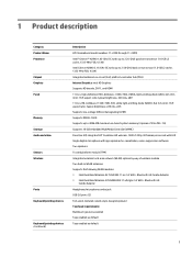
... on -circuit (SoC) platform controller hub (PCH) Internal Graphics: Intel HD Graphics Supports HD decode, DX11, and HDMI 11.6-in, high-definition (HD), AntiGlare, (1366×768), UWVA, light-emitting diode (LED), slim (3.0mm); 16:9 aspect ratio; 1 Product description Category Product Name Processor Chipset Graphics Panel Memory Storage Audio and video Sensors Wireless Ports Keyboard/pointing devices Keyboard/pointing devices (continued) Description HP Chromebook (model numbers 11-2200 through 11-2299) Intel® Celeron...
... on -circuit (SoC) platform controller hub (PCH) Internal Graphics: Intel HD Graphics Supports HD decode, DX11, and HDMI 11.6-in, high-definition (HD), AntiGlare, (1366×768), UWVA, light-emitting diode (LED), slim (3.0mm); 16:9 aspect ratio; 1 Product description Category Product Name Processor Chipset Graphics Panel Memory Storage Audio and video Sensors Wireless Ports Keyboard/pointing devices Keyboard/pointing devices (continued) Description HP Chromebook (model numbers 11-2200 through 11-2299) Intel® Celeron...
Maintenance and Service Guide
Page 12
... cable slot Power connector AC adapter light (4) Memory card reader Description Attaches an optional security cable to act as a deterrent, but it pops out. 6 Chapter 2 External component identification NOTE: The security cable is designed to the computer. To remove a card: ▲ Press in on the card it until it is using battery power. Connects an AC adapter. ● White: The AC adapter is connected and the battery is charged. ● Amber: The AC adapter is connected...
... cable slot Power connector AC adapter light (4) Memory card reader Description Attaches an optional security cable to act as a deterrent, but it pops out. 6 Chapter 2 External component identification NOTE: The security cable is designed to the computer. To remove a card: ▲ Press in on the card it until it is using battery power. Connects an AC adapter. ● White: The AC adapter is connected and the battery is charged. ● Amber: The AC adapter is connected...
Maintenance and Service Guide
Page 13
... injury, adjust the volume before putting on . ● Blinking white: Computer is in Sleep mode. ● Off: The computer is off. (2) Audio-out (headphone)/Audio-in (microphone). (3) USB 2.0 port Connect optional USB devices, such as a keyboard, mouse, external drive, printer, scanner or USB hub. (4) USB 3.0 charging (powered) port Connects an optional USB device, such as a highdefinition television, any compatible digital or audio component, or a high-speed High-Definition Multimedia Interface (HDMI) device. Some USB devices require power and require you to the jack, the...
... injury, adjust the volume before putting on . ● Blinking white: Computer is in Sleep mode. ● Off: The computer is off. (2) Audio-out (headphone)/Audio-in (microphone). (3) USB 2.0 port Connect optional USB devices, such as a keyboard, mouse, external drive, printer, scanner or USB hub. (4) USB 3.0 charging (powered) port Connects an optional USB device, such as a highdefinition television, any compatible digital or audio component, or a high-speed High-Definition Multimedia Interface (HDMI) device. Some USB devices require power and require you to the jack, the...
Maintenance and Service Guide
Page 17
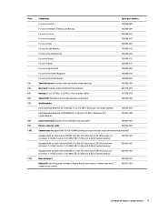
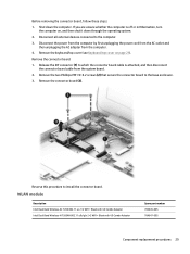
... (6) Speaker Kit (includes left and right speakers and cables) 788555-001 (7) WLAN module: Intel Dual Band Wireless-AC 7260 802.11 ac 2×2 WiFi + Bluetooth 4.0 Combo Adapter 784645-005 Intel Dual Band Wireless-N 7260AN 802.11 a/b/g/n 2×2 WiFi + Bluetooth 4.0 Combo Adapter 784647-005 (8) Connector board (includes SD Card Reader slot and cable) 783087-001 (9) Power connector cable 787922-001 (10) System board equipped with 16-GB of eMMC primary storage...
... (6) Speaker Kit (includes left and right speakers and cables) 788555-001 (7) WLAN module: Intel Dual Band Wireless-AC 7260 802.11 ac 2×2 WiFi + Bluetooth 4.0 Combo Adapter 784645-005 Intel Dual Band Wireless-N 7260AN 802.11 a/b/g/n 2×2 WiFi + Bluetooth 4.0 Combo Adapter 784647-005 (8) Connector board (includes SD Card Reader slot and cable) 783087-001 (9) Power connector cable 787922-001 (10) System board equipped with 16-GB of eMMC primary storage...
Maintenance and Service Guide
Page 21
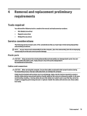
... at the points designated in their proper locations during disassembly and reassembly can damage the computer. Handle cables by parts being removed or replaced. 4 Removal and replacement preliminary requirements Tools required You will need the following tools to complete the removal and replacement procedures: ● Flat-bladed screw driver ● Magnetic screw driver ● Phillips P0 screw driver Service considerations The following sections include some...
... at the points designated in their proper locations during disassembly and reassembly can damage the computer. Handle cables by parts being removed or replaced. 4 Removal and replacement preliminary requirements Tools required You will need the following tools to complete the removal and replacement procedures: ● Flat-bladed screw driver ● Magnetic screw driver ● Phillips P0 screw driver Service considerations The following sections include some...
Maintenance and Service Guide
Page 26
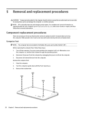
... included in the Rubber Kit, spare part number 822631-001. Turn off or in Hibernation, turn the computer on -screen instructions. Disconnect the power from the computer by an authorized service provider. NOTE: HP continually improves and changes product parts. Make special note of each screw size and location during removal and replacement. If you . 3. Close the computer. 2. 5 Removal and replacement procedures CAUTION: Components described in this...
... included in the Rubber Kit, spare part number 822631-001. Turn off or in Hibernation, turn the computer on -screen instructions. Disconnect the power from the computer by an authorized service provider. NOTE: HP continually improves and changes product parts. Make special note of each screw size and location during removal and replacement. If you . 3. Close the computer. 2. 5 Removal and replacement procedures CAUTION: Components described in this...
Maintenance and Service Guide
Page 34
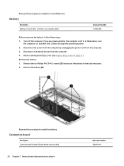
... battery. includes cable) Spare part number 767068-001 Before removing the battery, follow these steps: 1. Disconnect all external devices from the computer. 3. Remove the keyboard/top cover (see Keyboard/top cover on , and then shut it down through the operating system. 2. Disconnect the power from the computer by unplugging the power cord from the computer. 4. Connector board Description Connector board (includes SD Card Reader slot and cable) 28 Chapter 5 Removal and replacement procedures Spare part number...
... battery. includes cable) Spare part number 767068-001 Before removing the battery, follow these steps: 1. Disconnect all external devices from the computer. 3. Remove the keyboard/top cover (see Keyboard/top cover on , and then shut it down through the operating system. 2. Disconnect the power from the computer by unplugging the power cord from the computer. 4. Connector board Description Connector board (includes SD Card Reader slot and cable) 28 Chapter 5 Removal and replacement procedures Spare part number...
Maintenance and Service Guide
Page 35
... Band Wireless-N 7260AN 802.11 a/b/g/n 2×2 WiFi + Bluetooth 4.0 Combo Adapter Spare part number 784645-005 784647-005 Component replacement procedures 29 Reverse this procedure to the computer. 3. Before removing the connector board, follow these steps: 1. Disconnect the power from the computer by first unplugging the power cord from the AC outlet and then unplugging the AC adapter from the system board. 2. Disconnect all external devices connected to install...
... Band Wireless-N 7260AN 802.11 a/b/g/n 2×2 WiFi + Bluetooth 4.0 Combo Adapter Spare part number 784645-005 784647-005 Component replacement procedures 29 Reverse this procedure to the computer. 3. Before removing the connector board, follow these steps: 1. Disconnect the power from the computer by first unplugging the power cord from the AC outlet and then unplugging the AC adapter from the system board. 2. Disconnect all external devices connected to install...
Maintenance and Service Guide
Page 36
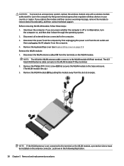
... module #1/Main terminal. Remove the WLAN module: 1. The #2/ black WLAN antenna cable connects to the computer. 3. NOTE: If the WLAN antenna is off or in Hibernation, turn the computer on the antenna connector, as shown in the following illustration. 30 Chapter 5 Removal and replacement procedures Shut down through the operating system. 2. Remove the keyboard/top cover (see Keyboard/top cover on the WLAN module. Remove the WLAN module...
... module #1/Main terminal. Remove the WLAN module: 1. The #2/ black WLAN antenna cable connects to the computer. 3. NOTE: If the WLAN antenna is off or in Hibernation, turn the computer on the antenna connector, as shown in the following illustration. 30 Chapter 5 Removal and replacement procedures Shut down through the operating system. 2. Remove the keyboard/top cover (see Keyboard/top cover on the WLAN module. Remove the WLAN module...
Maintenance and Service Guide
Page 39
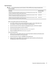
... storage and replacement thermal material. Disconnect the power from the computer by unplugging the power cord from the system board. 3. Remove the WLAN module (see Keyboard/top cover on page 29). Disconnect all external devices from the system board. 2. If you are unsure whether the computer is attached, and then disconnect the display panel cable from the system board. Remove the keyboard/top cover (see WLAN module on page...
... storage and replacement thermal material. Disconnect the power from the computer by unplugging the power cord from the system board. 3. Remove the WLAN module (see Keyboard/top cover on page 29). Disconnect all external devices from the system board. 2. If you are unsure whether the computer is attached, and then disconnect the display panel cable from the system board. Remove the keyboard/top cover (see WLAN module on page...
Maintenance and Service Guide
Page 56
...packaging 18 transporting 18 workstation 18 H HDMI port 7 HDMI-to-VGA adapter, spare part number 14 headphone jack 7 heat sink removal 26 spare part number 11, 26 hinge removal 43 spare part number 12, 43 J jacks audio-in 7 audio-out 7 headphone 7 microphone 7 K keyboard/top cover removal 21 spare part numbers 10, 21 L left-side component 6 lights power 7 webcam 3 M memory, product description 1 microphone location 3 product description 1 microphone jack 7 model name 1 O operating system, product description 2 P packaging guidelines 18 plastic parts, service considerations 15 50 Index
...packaging 18 transporting 18 workstation 18 H HDMI port 7 HDMI-to-VGA adapter, spare part number 14 headphone jack 7 heat sink removal 26 spare part number 11, 26 hinge removal 43 spare part number 12, 43 J jacks audio-in 7 audio-out 7 headphone 7 microphone 7 K keyboard/top cover removal 21 spare part numbers 10, 21 L left-side component 6 lights power 7 webcam 3 M memory, product description 1 microphone location 3 product description 1 microphone jack 7 model name 1 O operating system, product description 2 P packaging guidelines 18 plastic parts, service considerations 15 50 Index
Maintenance and Service Guide
Page 57
ports HDMI 7 product description 1 USB 7 power button 4 power connector cable removal 32 spare part number 11, 32 power cord set requirements 47 power light 7 power requirements, product description 1, 2 processor, product description 1 product description audio 1 chipset 1 display panel 1 graphics 1 memory 1 microphone 1 operating system 2 ports 1 power requirements 1, 2 processors 1 product name 1 sensors 1 serviceability 2 storage 1 video 1 wireless 1 product name 1 R removal/replacement procedures 20 right-side components 7 RJ45-to-USB adapter dongle, spare part number 14 Rubber Kit, spare...
ports HDMI 7 product description 1 USB 7 power button 4 power connector cable removal 32 spare part number 11, 32 power cord set requirements 47 power light 7 power requirements, product description 1, 2 processor, product description 1 product description audio 1 chipset 1 display panel 1 graphics 1 memory 1 microphone 1 operating system 2 ports 1 power requirements 1, 2 processors 1 product name 1 sensors 1 serviceability 2 storage 1 video 1 wireless 1 product name 1 R removal/replacement procedures 20 right-side components 7 RJ45-to-USB adapter dongle, spare part number 14 Rubber Kit, spare...


