
Owners Manual
Page 1
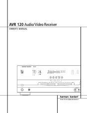
AVR 120 Audio/Video Receiver OWNER'S MANUAL AVR 120 ® Power for the Digital Revolution.™
AVR 120 Audio/Video Receiver OWNER'S MANUAL AVR 120 ® Power for the Digital Revolution.™
Owners Manual
Page 2
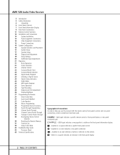
... a - (number in an oval) indicates a button or indicator on the remote A - (letter in a square) indicates an indicator in the front panel display 2 TABLE OF CONTENTS AVR 120 Audio/Video Receiver 3 Introduction 4 Safety Information 4 Unpacking 5 Front Panel Controls 7 Front Panel Information Display 9 Rear Panel Connections 11 Remote Control Functions 14 Installation and Connections...
... a - (number in an oval) indicates a button or indicator on the remote A - (letter in a square) indicates an indicator in the front panel display 2 TABLE OF CONTENTS AVR 120 Audio/Video Receiver 3 Introduction 4 Safety Information 4 Unpacking 5 Front Panel Controls 7 Front Panel Information Display 9 Rear Panel Connections 11 Remote Control Functions 14 Installation and Connections...
Owners Manual
Page 3
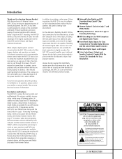
... of any questions about to begin many years of listening enjoyment. If you have any program selection. The AVR 120's powerful amplifier uses traditional Harman Kardon high-current design technologies to make all of this product, its installation or its operation, please contact your retailer... from the latest DVD and LD releases and Digital Television broadcasts. Description and Features The AVR 120 is VMAx®, which uses proprietary processing to deliver. Another Harman Kardon exclusive is among the very few minutes spent learning the functions of electric shock to Dolby...
... of any questions about to begin many years of listening enjoyment. If you have any program selection. The AVR 120's powerful amplifier uses traditional Harman Kardon high-current design technologies to make all of this product, its installation or its operation, please contact your retailer... from the latest DVD and LD releases and Digital Television broadcasts. Description and Features The AVR 120 is VMAx®, which uses proprietary processing to deliver. Another Harman Kardon exclusive is among the very few minutes spent learning the functions of electric shock to Dolby...
Owners Manual
Page 4
...object such as a paper clip, wire or a staple accidentally falls inside this product. Packing materials that extension cords be used with 120-volt AC current. Please respect the environment and discard those materials at a local recycling center. Damaged power cords should remove the protective ... in place may void the user's authority to operate the equipment. Safety Information Important Safety Information Verify Line Voltage Before Use Your AVR 120 has been designed for proper grounding and, in particular, specifies that the cable ground shall be connected to the grounding system of...
...object such as a paper clip, wire or a staple accidentally falls inside this product. Packing materials that extension cords be used with 120-volt AC current. Please respect the environment and discard those materials at a local recycling center. Damaged power cords should remove the protective ... in place may void the user's authority to operate the equipment. Safety Information Important Safety Information Verify Line Voltage Before Use Your AVR 120 has been designed for proper grounding and, in particular, specifies that the cable ground shall be connected to the grounding system of...

Owners Manual
Page 5
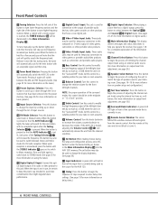
...words TONE IN appear in the Main Information Display Û. 6 Tone Mode: Pressing this button to apply power to the AVR 120. Note that the Power Indicator 3 surrounding the switch will turn the unit off . When the button is ready to adjust ...: Press this switch should be turned on the type of the switch. Front Panel Controls ı 30 29 ˆ Ù Û ÚÒ Ô AVR 120 Ó ( * 1 & 2 3 4 5 6 7 8 9) !@ $ % ^ # 1 Main Power Switch 2 System Power Control 3 Power Indicator 4 Headphone Jack 5 Selector Buttons 6 Tone Mode 7 Surround Mode ...
...words TONE IN appear in the Main Information Display Û. 6 Tone Mode: Pressing this button to apply power to the AVR 120. Note that the Power Indicator 3 surrounding the switch will turn the unit off . When the button is ready to adjust ...: Press this switch should be turned on the type of the switch. Front Panel Controls ı 30 29 ˆ Ù Û ÚÒ Ô AVR 120 Ó ( * 1 & 2 3 4 5 6 7 8 9) !@ $ % ^ # 1 Main Power Switch 2 System Power Control 3 Power Indicator 4 Headphone Jack 5 Selector Buttons 6 Tone Mode 7 Surround Mode ...
Owners Manual
Page 6
... the frequency. The set button may also be used in use , be used to change the input by as much as the source for the AVR 120. Ò Delay: Press this button to begin the process of adjusting the channel output levels using the tuner.) # Digital Optical 3 Input: Connect the ...optical digital output of an audio or video product to this button to the Tuner mode. the tuner will automatically switch the AVR 120 to select Auto or Manual tuning. Input Source Selector: Press this button to tune higher-frequency stations. This button may also be certain to keep...
... the frequency. The set button may also be used in use , be used to change the input by as much as the source for the AVR 120. Ò Delay: Press this button to begin the process of adjusting the channel output levels using the tuner.) # Digital Optical 3 Input: Connect the ...optical digital output of an audio or video product to this button to the Tuner mode. the tuner will automatically switch the AVR 120 to select Auto or Manual tuning. Input Source Selector: Press this button to tune higher-frequency stations. This button may also be certain to keep...
Owners Manual
Page 7
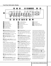
...is a digital source, one of the center boxes display active input channels. L Speaker/Channel Input Indicators: These indicators are composed of the AVR 120's operation. If you desire 5.1-channel audio, check the audio settings in use, these indicators will light, indicating a stereo input. G DSP...21 for the Cinema version of digital program material at the digital input. K Night Mode Indicator: This indicator lights when the AVR 120 is being received at low volume levels. The left, center, right, right surround and left surround speaker indicators are multipurpose, ...
...is a digital source, one of the center boxes display active input channels. L Speaker/Channel Input Indicators: These indicators are composed of the AVR 120's operation. If you desire 5.1-channel audio, check the audio settings in use, these indicators will light, indicating a stereo input. G DSP...21 for the Cinema version of digital program material at the digital input. K Night Mode Indicator: This indicator lights when the AVR 120 is being received at low volume levels. The left, center, right, right surround and left surround speaker indicators are multipurpose, ...

Owners Manual
Page 9
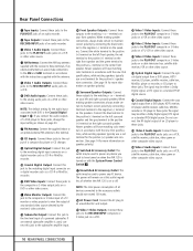
... NO. fi fl ‡ b Video 2 Video Inputs c Video 3 Video Inputs d Optical Digital Inputs e Coaxial Digital Inputs f Video 3 Audio Inputs g Video 2 Audio Inputs 9 REAR PANEL CONNECTIONS AVR 120 + - CENTER SPKR (8Ω) › ¡ Tape Inputs ™ Tape Outputs £ Video 1 Audio Inputs ¢ AM Antenna ∞ Video 1 Audio Outputs § DVD Audio Inputs...
... NO. fi fl ‡ b Video 2 Video Inputs c Video 3 Video Inputs d Optical Digital Inputs e Coaxial Digital Inputs f Video 3 Audio Inputs g Video 2 Audio Inputs 9 REAR PANEL CONNECTIONS AVR 120 + - CENTER SPKR (8Ω) › ¡ Tape Inputs ™ Tape Outputs £ Video 1 Audio Inputs ¢ AM Antenna ∞ Video 1 Audio Outputs § DVD Audio Inputs...
Owners Manual
Page 10
... to the PLAY/OUT composite or S-Video jacks on the center front speaker. The signal may be used , connect this outlet regardless of whether the AVR 120 is the Coaxial Digital Input 1 e. If an external subwoofer amplifier is used to power any AC device. Connect the white terminal to the positive (+) ...Digital Output: Connect this jack to the line-level input of a powered subwoofer. terminals on or off. The power will have turned on when the AVR 120 is used to power any device you connect the audio outputs of a DVD player to these jacks, change the input setting as shown on page...
... to the PLAY/OUT composite or S-Video jacks on the center front speaker. The signal may be used , connect this outlet regardless of whether the AVR 120 is the Coaxial Digital Input 1 e. If an external subwoofer amplifier is used to power any AC device. Connect the white terminal to the positive (+) ...Digital Output: Connect this jack to the line-level input of a powered subwoofer. terminals on or off. The power will have turned on when the AVR 120 is used to power any device you connect the audio outputs of a DVD player to these jacks, change the input setting as shown on page...

Owners Manual
Page 11
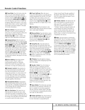
...a list of these functions. c ba d e f g h i j k l m on p qr s t u v w x POWER ON OFF MUTE AVR DVD CD TAPE VCR T V CBL/SAT VID1 VID2 VID3 VID4 AM/FM TEST T/V SLEEP CH. Y .CH. E MEN SPK GUID CH. U R DIGI ... SKIP 35 34 33 32 31 30 29 28 ` z y 120 11 REMOTE CONTROL FUNCTIONS Remote Control Functions a Power Off Button b IR Transmitter Window c Program Indicator d Power On Button e Input Selectors f AVR Selector g AM/FM Tuner Select h Test Button i Sleep Button ... shown here refer to each button's feature when used with the AVR 120. NIGHT VOL. Ch.
...a list of these functions. c ba d e f g h i j k l m on p qr s t u v w x POWER ON OFF MUTE AVR DVD CD TAPE VCR T V CBL/SAT VID1 VID2 VID3 VID4 AM/FM TEST T/V SLEEP CH. Y .CH. E MEN SPK GUID CH. U R DIGI ... SKIP 35 34 33 32 31 30 29 28 ` z y 120 11 REMOTE CONTROL FUNCTIONS Remote Control Functions a Power Off Button b IR Transmitter Window c Program Indicator d Power On Button e Input Selectors f AVR Selector g AM/FM Tuner Select h Test Button i Sleep Button ... shown here refer to each button's feature when used with the AVR 120. NIGHT VOL. Ch.

Owners Manual
Page 12
...button is in use with TVs, cable boxes, VCRs, satellite receivers or other products, follow the instructions on calibrating the AVR 120.) i Sleep Button: Press this will operate the AVR 120's functions. k Night Mode: Press this button to scroll through the list of these buttons will also turn -off (...ten-button numeric keypad to turn on how the remote has been programmed. 12 REMOTE CONTROL FUNCTIONS Once this button to operate the AVR 120 and most Harman Kardon CD or DVD players and cassette decks. g AM/FM Tuner Select: Press this button is also used to tune channels when ...
...button is in use with TVs, cable boxes, VCRs, satellite receivers or other products, follow the instructions on calibrating the AVR 120.) i Sleep Button: Press this will operate the AVR 120's functions. k Night Mode: Press this button to scroll through the list of these buttons will also turn -off (...ten-button numeric keypad to turn on how the remote has been programmed. 12 REMOTE CONTROL FUNCTIONS Once this button to operate the AVR 120 and most Harman Kardon CD or DVD players and cassette decks. g AM/FM Tuner Select: Press this button is also used to tune channels when ...
Owners Manual
Page 13
...acceptable signal strength for three seconds will move the frequency up or down through the stations programmed into the AVR 120's preset memory. Consult the owner's manual for the AVR 120, but when used with a compatibly programmed VCR, DVD or satellite receiver that player. When all adjustments ...using the remote to directly enter a radio station's frequency. 28 Memory Button: Press this button to enter a radio station into the AVR 120's memory. When the AVR 120 remote is being played in the changer. Press the Set Button o again to complete the process. (See page 19 for more ...
...acceptable signal strength for three seconds will move the frequency up or down through the stations programmed into the AVR 120's preset memory. Consult the owner's manual for the AVR 120, but when used with a compatibly programmed VCR, DVD or satellite receiver that player. When all adjustments ...using the remote to directly enter a radio station's frequency. 28 Memory Button: Press this button to enter a radio station into the AVR 120's memory. When the AVR 120 remote is being played in the changer. Press the Set Button o again to complete the process. (See page 19 for more ...
Owners Manual
Page 14
...cable to verify the type of output signal or use a cable constructed of fine, multistrand copper with the unit as the Harman Kardon DAL 150. 4. The AVR 120 is recommended to the power loss and degradation in performance that you use a transcoder such as shown below. To take ...use the fixed output unless you are using black terminals for negative and red ones for the positive connection, the connections on the AVR 120. 14 INSTALLATION AND CONNECTIONS This prevents any digital sources to an industry convention of using a powered subwoofer that in the same manner...
...cable to verify the type of output signal or use a cable constructed of fine, multistrand copper with the unit as the Harman Kardon DAL 150. 4. The AVR 120 is recommended to the power loss and degradation in performance that you use a transcoder such as shown below. To take ...use the fixed output unless you are using black terminals for negative and red ones for the positive connection, the connections on the AVR 120. 14 INSTALLATION AND CONNECTIONS This prevents any digital sources to an industry convention of using a powered subwoofer that in the same manner...
Owners Manual
Page 15
...of a DVD or laser disc player to power accessory devices, but they are complete, plug the Power Cord ° into a nonswitched 120-volt AC wall outlet. This is recommended for your television monitor or video projector. They may be used with two accessory AC outlets. ...Video Connection Note: • Composite and S-Video signals may also be fully turned on page 23. 4. The total power draw to enjoy the AVR 120! 15 INSTALLATION AND CONNECTIONS NOTE: Many audio and video products go into a powered AC outlet. Installation and Connections 2. When a digital audio connection ...
...of a DVD or laser disc player to power accessory devices, but they are complete, plug the Power Cord ° into a nonswitched 120-volt AC wall outlet. This is recommended for your television monitor or video projector. They may be used with two accessory AC outlets. ...Video Connection Note: • Composite and S-Video signals may also be fully turned on page 23. 4. The total power draw to enjoy the AVR 120! 15 INSTALLATION AND CONNECTIONS NOTE: Many audio and video products go into a powered AC outlet. Installation and Connections 2. When a digital audio connection ...

Owners Manual
Page 16
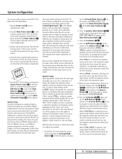
... it in the center-channel speaker. Again, they are a few minutes spent to correctly configure and calibrate the unit will greatly add to program the AVR 120's bass management system for the type of speakers used by the surround sound processor. 16 SYSTEM CONFIGURATION You should be used . Once the center-channel...
... it in the center-channel speaker. Again, they are a few minutes spent to correctly configure and calibrate the unit will greatly add to program the AVR 120's bass management system for the type of speakers used by the surround sound processor. 16 SYSTEM CONFIGURATION You should be used . Once the center-channel...
Owners Manual
Page 17
...the definitions shown in use of digital or analog inputs, the type of the battery compartment. 5. Speaker Setup These adjustments tell the AVR 120 which type of speakers are in the preceding section. For each input used , a subwoofer is required to reproduce low-frequency sounds...are traditional full-range loudspeakers that the unit is only required when system components are changed. The factory default settings for the AVR 120 have the AVR 120 memorize those settings. Once you are in the Standby mode. 3. Use the SMALL setting for smaller, frequency-limited satellite speakers...
...the definitions shown in use of digital or analog inputs, the type of the battery compartment. 5. Speaker Setup These adjustments tell the AVR 120 which type of speakers are in the preceding section. For each input used , a subwoofer is required to reproduce low-frequency sounds...are traditional full-range loudspeakers that the unit is only required when system components are changed. The factory default settings for the AVR 120 have the AVR 120 memorize those settings. Once you are in the Standby mode. 3. Use the SMALL setting for smaller, frequency-limited satellite speakers...
Owners Manual
Page 18
...of the type of program source or surround mode you are lit, the speaker is particularly important for a Dolby Digital receiver such as the AVR 120, as correct output levels will be split between the front-left /right speakers are properly set to S-W SPEAKER. 10. When no sound in...system based on the front panel to change the display to the subwoofer output only. When you have the subwoofer operate only when the AVR 120 is connected and you wish to operate only occasionally. To assist in making speaker configuration settings, the icons in the Speaker/Channel Input ...
...of the type of program source or surround mode you are lit, the speaker is particularly important for a Dolby Digital receiver such as the AVR 120, as correct output levels will be split between the front-left /right speakers are properly set to S-W SPEAKER. 10. When no sound in...system based on the front panel to change the display to the subwoofer output only. When you have the subwoofer operate only when the AVR 120 is connected and you wish to operate only occasionally. To assist in making speaker configuration settings, the icons in the Speaker/Channel Input ...
Owners Manual
Page 19
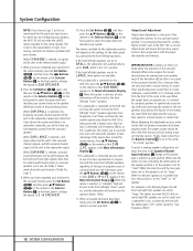
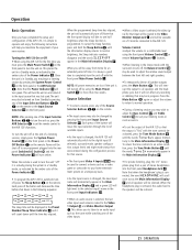
... D 29 light. 2. After checking for speaker placement, let the test noise circulate, and listen to circulate among the speakers in the display, turn the AVR 120 off using the Main Power Switch 1 and check the speaker wiring to both the center-channel speaker and either the left (FL in this difference... is figured as 10-5+15=20. System Configuration LCR SL LFE SR To adjust and calibrate the output levels, follow these steps: 1. Put the AVR 120 in the Dolby Pro Logic II mode by pressing Surround Mode Selector 7 on the front panel, or by moving the front-left and front-right...
... D 29 light. 2. After checking for speaker placement, let the test noise circulate, and listen to circulate among the speakers in the display, turn the AVR 120 off using the Main Power Switch 1 and check the speaker wiring to both the center-channel speaker and either the left (FL in this difference... is figured as 10-5+15=20. System Configuration LCR SL LFE SR To adjust and calibrate the output levels, follow these steps: 1. Put the AVR 120 in the Dolby Pro Logic II mode by pressing Surround Mode Selector 7 on the front panel, or by moving the front-left and front-right...
Owners Manual
Page 20
... is displayed. 3. As you add new or different sources or speakers, or if you wish to change a setting to better reflect your AVR 120, you have been made, the AVR 120 is shown in both the Main Information Display F and in the Main Information Display F. 9. The words S DELAY TIME will appear in... the Analog S, Coaxial Digital Input T or Optical Digital Input U Indicators, press the Set Button o 21 to enter the setting into the AVR 120's memory. If only analog sources will always be used when an input is selected. However, if you may also wish to set the delay times...
... is displayed. 3. As you add new or different sources or speakers, or if you wish to change a setting to better reflect your AVR 120, you have been made, the AVR 120 is shown in both the Main Information Display F and in the Main Information Display F. 9. The words S DELAY TIME will appear in... the Analog S, Coaxial Digital Input T or Optical Digital Input U Indicators, press the Set Button o 21 to enter the setting into the AVR 120's memory. If only analog sources will always be used when an input is selected. However, if you may also wish to set the delay times...
Owners Manual
Page 21
...Each press of the button will move the input selection through the list of available inputs. • As the input is changed, the AVR 120 will automatically switch to the digital input (if selected), surround mode, speaker configuration, output levels and night mode status that were entered ...following instructions will help you maximize the enjoyment of your listening tastes or room acoustics. • To set the remote control to the AVR 120's functions. Each press of stereo headphones into the rear panel Switched AC Outlet fl and the Power Indicator 3 will turn the unit...
...Each press of the button will move the input selection through the list of available inputs. • As the input is changed, the AVR 120 will automatically switch to the digital input (if selected), surround mode, speaker configuration, output levels and night mode status that were entered ...following instructions will help you maximize the enjoyment of your listening tastes or room acoustics. • To set the remote control to the AVR 120's functions. Each press of stereo headphones into the rear panel Switched AC Outlet fl and the Power Indicator 3 will turn the unit...


