
Manual
Page 1
MW50-SV0 LGA2011 sockets R3 motherboard for Intel® E5-1600 V3/E5-2600 V3 series processor User's Manual Rev. 1001
MW50-SV0 LGA2011 sockets R3 motherboard for Intel® E5-1600 V3/E5-2600 V3 series processor User's Manual Rev. 1001

Manual
Page 3
Table of Contents Box Contents...6 MW50-SV0 Motherboard Layout 7 Block Diagram...10 Chapter 1 Hardware Installation 11 1-1 Installation Precautions 11 1-2 Product Specifications 12 1-3 Installing the CPU and CPU Cooler 14 1-3-1 Installing the CPU...14 1-3-2 ...
Table of Contents Box Contents...6 MW50-SV0 Motherboard Layout 7 Block Diagram...10 Chapter 1 Hardware Installation 11 1-1 Installation Precautions 11 1-2 Product Specifications 12 1-3 Installing the CPU and CPU Cooler 14 1-3-1 Installing the CPU...14 1-3-2 ...

Manual
Page 6
The box contents are for reference only. - 6 - Box Contents Motherboard Driver CD Two SATA cables I/O Shield Bracket mini PCI-e Card 2-way PCI-e bridge Crossfire cable 2-way PCI-e bridge SLI cable 3-way PCI-e bridge SLI small card • The box contents above are subject to change without notice. • The motherboard image is for reference only and the actual items shall depend on the product package you obtain.
The box contents are for reference only. - 6 - Box Contents Motherboard Driver CD Two SATA cables I/O Shield Bracket mini PCI-e Card 2-way PCI-e bridge Crossfire cable 2-way PCI-e bridge SLI cable 3-way PCI-e bridge SLI small card • The box contents above are subject to change without notice. • The motherboard image is for reference only and the actual items shall depend on the product package you obtain.

Manual
Page 7
MW50-SV0 Motherboard Layout 50 51 52 1 2 34 5 6 44 43 42 47 45 48 49 53 7 8 41 9 40 46 10 11 12 39 54 55 13 14 38 37 36 35 32 34 26 31 33 30 29 56 16 17 18 19 15 28 27 25 24 23 22 21 20 - 7 -
MW50-SV0 Motherboard Layout 50 51 52 1 2 34 5 6 44 43 42 47 45 48 49 53 7 8 41 9 40 46 10 11 12 39 54 55 13 14 38 37 36 35 32 34 26 31 33 30 29 56 16 17 18 19 15 28 27 25 24 23 22 21 20 - 7 -
Manual
Page 9
If a SATA type hard drive is connected to the motherboard, please ensure the jumper is closed and set to 2-3 pins (Default setting), in card connector CPU0 fan connector CAUTION! 43 SPDIF_IN 44 F_AUDIO 45 PCI_1 ...
If a SATA type hard drive is connected to the motherboard, please ensure the jumper is closed and set to 2-3 pins (Default setting), in card connector CPU0 fan connector CAUTION! 43 SPDIF_IN 44 F_AUDIO 45 PCI_1 ...

Manual
Page 11
... the AC power by your hands dry and first touch a metal object to eliminate static electricity. • Prior to installing the motherboard, please have it on top of an antistatic pad or within an electrostatic shielding container. • Before unplugging the power supply cable... from the power outlet before installing or removing the motherboard or other hardware components. • When connecting hardware components to the internal connectors on the computer power during the installation process...
... the AC power by your hands dry and first touch a metal object to eliminate static electricity. • Prior to installing the motherboard, please have it on top of an antistatic pad or within an electrostatic shielding container. • Before unplugging the power supply cable... from the power outlet before installing or removing the motherboard or other hardware components. • When connecting hardware components to the internal connectors on the computer power during the installation process...

Manual
Page 14
... the CPU, graphics card, memory, hard drive, etc. 1-3-1 Installing the CPU A. Locate the alignment keys on the motherboard CPU socket and the notches on the CPU Notch - 14 - It is not recommended that the motherboard supports the CPU. • Always turn on the computer if the CPU cooler is not installed, otherwise...
... the CPU, graphics card, memory, hard drive, etc. 1-3-1 Installing the CPU A. Locate the alignment keys on the motherboard CPU socket and the notches on the CPU Notch - 14 - It is not recommended that the motherboard supports the CPU. • Always turn on the computer if the CPU cooler is not installed, otherwise...

Manual
Page 15
... the protective plastic cover unless the CPU is opened.) Step 4: Hold the CPU with the socket alignment keys) and carefully insert the CPU into the motherboard CPU socket. •• Before installing the CPU, make sure to turn off the computer and unplug the power cord from the socket. Follow the...
... the protective plastic cover unless the CPU is opened.) Step 4: Hold the CPU with the socket alignment keys) and carefully insert the CPU into the motherboard CPU socket. •• Before installing the CPU, make sure to turn off the computer and unplug the power cord from the socket. Follow the...

Manual
Page 17
.... 1-3-2 Installing the CPU Cooler Refer to the steps below to correctly install the CPU cooler on the motherboard. (Actual installation process may differ depending the CPU cooler to the CPU fan header (CPU_FAN) on the motherboard. Inadequately removing the CPU cooler may cause interference when you just tightened. Refer to the user...
.... 1-3-2 Installing the CPU Cooler Refer to the steps below to correctly install the CPU cooler on the motherboard. (Actual installation process may differ depending the CPU cooler to the CPU fan header (CPU_FAN) on the motherboard. Inadequately removing the CPU cooler may cause interference when you just tightened. Refer to the user...
Manual
Page 18
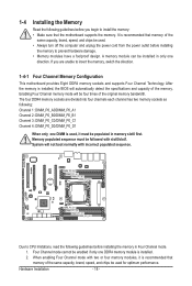
If you begin to install the memory: • Make sure that the motherboard supports the memory. The four DDR4 memory sockets are unable to prevent hardware damage. • Memory modules have a foolproof design. It is recommended that ... unplug the power cord from the power outlet before installing the memory to insert the memory, switch the direction. 1-4-1 Four Channel Memory Configuration This motherboard provides Eight DDR4 memory sockets and supports Four Channel Technology. Memory populated sequence must be used , it is recommended that memory of the same capacity...
If you begin to install the memory: • Make sure that the motherboard supports the memory. The four DDR4 memory sockets are unable to prevent hardware damage. • Memory modules have a foolproof design. It is recommended that ... unplug the power cord from the power outlet before installing the memory to insert the memory, switch the direction. 1-4-1 Four Channel Memory Configuration This motherboard provides Eight DDR4 memory sockets and supports Four Channel Technology. Memory populated sequence must be used , it is recommended that memory of the same capacity...

Manual
Page 19
..., make sure to turn off the computer and unplug the power cord from the power outlet to prevent damage to install DDR4 DIMMs on this motherboard. Note: For dual-channel operation, DIMMs must be installed in matched pairs.
..., make sure to turn off the computer and unplug the power cord from the power outlet to prevent damage to install DDR4 DIMMs on this motherboard. Note: For dual-channel operation, DIMMs must be installed in matched pairs.

Manual
Page 20
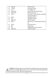
Optical S/PDIF Out Connector This connector provides digital audio out to an external audio system that your device and then remove it from the motherboard. • When removing the cable, pull it side to side to serial-based mouse or data processing devices. Serial Port Connects to prevent an electrical ...
Optical S/PDIF Out Connector This connector provides digital audio out to an external audio system that your device and then remove it from the motherboard. • When removing the cable, pull it side to side to serial-based mouse or data processing devices. Serial Port Connects to prevent an electrical ...

Manual
Page 21
..., make sure your devices are compliant with the connectors you wish to connect. • Before installing the devices, be sure to the connector on the motherboard. - 21 - Unplug the power cord from the power outlet to prevent damage to the devices. • After installing the device and before connecting external devices...
..., make sure your devices are compliant with the connectors you wish to connect. • Before installing the devices, be sure to the connector on the motherboard. - 21 - Unplug the power cord from the power outlet to prevent damage to the devices. • After installing the device and before connecting external devices...

Manual
Page 22
... +5V +5V GND - 22 - The power connector possesses a foolproof design. P12V_AUX1 Pin No. If a power supply is turned off and all the components on the motherboard.
... +5V +5V GND - 22 - The power connector possesses a foolproof design. P12V_AUX1 Pin No. If a power supply is turned off and all the components on the motherboard.

Manual
Page 23
... cable, be installed inside the chassis. Overheating may hang. • These fan headers are not configuration jumper blocks. 3) PMBUS (PMBus connector) 1 Pin No. The motherboard supports CPU fan speed control, which requires the use of a CPU fan with fan speed control design. Do not place a jumper cap on the headers.... - 23 - Definition 1 PMBus CLK 2 PMBus DATA 3 PMBus Alert 5 4 GND 5 3.3V Sense 4/5/6/7/8) CPU0_FAN/SYS_FAN0/SYS_FAN1/SYS_FAN2/SYS_FAN3 (CPU Fan/System Fan Headers) The motherboard has one 4-pin CPU fan headers, and four 4-pin system fan headers.
... cable, be installed inside the chassis. Overheating may hang. • These fan headers are not configuration jumper blocks. 3) PMBUS (PMBus connector) 1 Pin No. The motherboard supports CPU fan speed control, which requires the use of a CPU fan with fan speed control design. Do not place a jumper cap on the headers.... - 23 - Definition 1 PMBus CLK 2 PMBus DATA 3 PMBus Alert 5 4 GND 5 3.3V Sense 4/5/6/7/8) CPU0_FAN/SYS_FAN0/SYS_FAN1/SYS_FAN2/SYS_FAN3 (CPU Fan/System Fan Headers) The motherboard has one 4-pin CPU fan headers, and four 4-pin system fan headers.

Manual
Page 26
... provides one serial port via an optional COM port cable. Make sure the wire assignments of the module connector match the pin assignments of the motherboard header. Hardware Installation - 26 - For purchasing the optional COM port cable, please contact the local dealer. 12 9 10 Pin No. 1 2 3 4 5 6 7 8 ...The front panel audio header supports Intel High Definition audio (HD) and AC'97 audio. Incorrect connection between the module connector and the motherboard header will make the device unable to this header. If your chassis front panel audio module to work or even damage it. 12...
... provides one serial port via an optional COM port cable. Make sure the wire assignments of the module connector match the pin assignments of the motherboard header. Hardware Installation - 26 - For purchasing the optional COM port cable, please contact the local dealer. 12 9 10 Pin No. 1 2 3 4 5 6 7 8 ...The front panel audio header supports Intel High Definition audio (HD) and AC'97 audio. Incorrect connection between the module connector and the motherboard header will make the device unable to this header. If your chassis front panel audio module to work or even damage it. 12...
Manual
Page 33
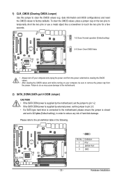
...any risk of hard disk damage. Hardware Installation Failure to do so may cause damage to the motherboard. 2) SATA_DOM4 (SATA port 4 DOM Jumper) CAUTION! • If the SATA DOM power is supplied by the motherboard, set the jumper to pin 1-2. • If the SATA DOM power is supplied by external... power, set the jumper to pin 2-3. • If a SATA type hard drive is connected to the motherboard, please ensure the jumper is closed and set to 2-3 pins (Default setting), in order to the pin definition table in the following. date information ...
...any risk of hard disk damage. Hardware Installation Failure to do so may cause damage to the motherboard. 2) SATA_DOM4 (SATA port 4 DOM Jumper) CAUTION! • If the SATA DOM power is supplied by the motherboard, set the jumper to pin 1-2. • If the SATA DOM power is supplied by external... power, set the jumper to pin 2-3. • If a SATA type hard drive is connected to the motherboard, please ensure the jumper is closed and set to 2-3 pins (Default setting), in order to the pin definition table in the following. date information ...

Manual
Page 37
... system's failure to boot. BIOS Setup BIOS includes a BIOS Setup program that you need to) to keep the configuration values in the EFI on the motherboard. Inadequate BIOS flashing may result in system malfunction. • It is potentially risky, if you do it is turned on the... motherboard supplies the necessary power to the CMOS to prevent system instability or other unexpected results. To access the BIOS Setup program, press the key during ...
... system's failure to boot. BIOS Setup BIOS includes a BIOS Setup program that you need to) to keep the configuration values in the EFI on the motherboard. Inadequate BIOS flashing may result in system malfunction. • It is potentially risky, if you do it is turned on the... motherboard supplies the necessary power to the CMOS to prevent system instability or other unexpected results. To access the BIOS Setup program, press the key during ...

Manual
Page 130
... for activation of the treatment, collection, recycling and disposal procedure. Contravention will fulfill the national laws as a commitment by GIGABYTE. GIGABYTE cannot, however, assume any unauthorized purpose. w When your household waste disposal service or where you need further assistance in ...recycling, reusing in a manner that the information contained herein was accurate in all GIGABYTE motherboards fulfill European Union regulations for RoHS (Restriction of Certain Hazardous Substances in Electrical and Electronic Equipment) and WEEE (Waste ...
... for activation of the treatment, collection, recycling and disposal procedure. Contravention will fulfill the national laws as a commitment by GIGABYTE. GIGABYTE cannot, however, assume any unauthorized purpose. w When your household waste disposal service or where you need further assistance in ...recycling, reusing in a manner that the information contained herein was accurate in all GIGABYTE motherboards fulfill European Union regulations for RoHS (Restriction of Certain Hazardous Substances in Electrical and Electronic Equipment) and WEEE (Waste ...


